roco 10727 User manual

10727
Elektronisches Regelteil
Electronic control unit
Régulateur électronique
Regolatore elettronico
Elektronische snelheidsregelaar
Inhaltsverzeichnis
Table of Contents
Table des matières
Indice
Inhoudsopgave
Fig. 1 – 3 ............................. 2
D
............................. 3 – 4
GB
............................. 5 – 6
F
............................. 7 – 8
I
............................. 8 – 9
NL
............................. 10 – 11
Fig. 4 ............................. 12
8010727920 VII_2009 .indd 1 22.06.2011 11:06:10

2
D
2
230 V ~
1
8010727100
10725
10718
Fig. 1
Fig. 2
Fig. 3
10727
10727
10727
2
3
1
3
2
1
2
3
8010727920 VII_2009 .indd 2 22.06.2011 11:06:14

3
3
Elektronisches Regelteil 10727
Zur Beachtung:
Das Regelteil Art.- Nr. 10727 wurde insbesondere für den Einsatz zusammen mit dem Steckernetzteil Art.-
Nr. 8010727100 entwickelt. Es ist auch möglich das Regelteil 10727 mit den Transformatoren 10718 oder
10725 zu betreiben (Fig. 1-3). Dabei ist allerdings zu beachten, dass auf Grund der höheren Ausgangs-
spannung die Lokomotiven etwas zu schnell gegenüber dem Vorbild fahren.
Verwendungsbereich
Impulsbreitengesteuerte Fahrstromversorgung mit stufenloser Geschwindigkeitsregelung für Gleichstrom-
Triebfahrzeuge.
Inbetriebnahme:
Das Regelteil ist vorrangig in Verbindung mit dem Transformator Art. Nr. 10718, 10725 und dem Steckernetzteil
Art. Nr. 8010727100 einzusetzen , die es mit ca. 15V Wechsel- oder Gleichstrom versorgen. An der Gleisbuchse
gibt das Regelteil eine impulsbreitengesteuerte, stufenlos regelbare Gleichstrom-Fahrspannung von maximal 18V
(maximale Impulshöhe) ab. (Vgl. Fig. 4)
1. Spannungsversorgungsbuchse
An der Spannungsversorgungsbuchse muss der Transformator angeschlossen werden. (Fig. 1-3)
2. Gleisbuchse
An dieser Buchse wird das Gleis angeschlossen. (Fig. 1-3))
3. Drehknopf:
mit ihm wird die Fahrtrichtung der Lokomotive gewählt und ihre Geschwindigkeit stufenlos geregelt: je weiter der
Drehknopf von der Mittelstellung weggedreht wird, umso höher ist die Geschwindigkeit der Lokomotive. In der
Mittelstellung (0-Stellung) des Drehknopfes ist der Fahrstrom abgeschaltet und das Regelteil elektrisch von der
Gleisanlage (bzw. der Oberleitung) getrennt. Er dient auch zum Rücksetzen nach einem Kurzschluss.
Achtung
Auf Grund ihres Regelungsprinzipes eignen sich impuls-breitengesteuerte Fahrregler nicht für Glockenankermoto-
ren mit eisenlosem Anker (Beispielsweise Faulhaber, Escap, Canon und andere); der Einsatz impulsbreitengesteu-
erter Fahrregler bei Glockenankermotoren kann zu irreparabelen Schäden an dieser Motorbauart führen.
Da das Regelteil nicht über eine eingebaute galvanische Trennung zwischen dem Eingang und dem geregel-
ten Gleichstrom-Ausgang verfügt, dürfen nur dann mehrere Regelteile an einem gemeinsamen Transforma-
tor betrieben werden, wenn alle Fahrzeuge Ihrer Anlage entweder nur über eine Unterleitung oder nur über
Oberleitung betrieben werden! Ein Mischbetrieb mit Unter- und Oberleitung ist nur dann störungsfrei mög-
lich, wenn für jeden Regler (gleichgültig, ob Ober- oder Unterleitung) ein eigener Transformator zur Verfü-
gung steht. Eine Gruppenstromversorgung (d.h. alle Regler für Unterleitung an einen Transformator und alle
Regler für Oberleitung an eine anderen Transformator) führt bei Mischbetrieb zu gegenseitger Beeinflussung
der verschiedenen Fahrstrom-Kreise und somit zu unvorhersagbaren Reaktionen der Fahrzeuge. Bei reinem
Unter- oder reinem Oberleitungsbetrieb dürfen mehrere Regelteile an einem gemeinsamen Transformator
betrieben werden (bei reinem Unterleitungsbetrieb Isolierschienenverbinder jeweils in beiden Fahrschienen,
bei reinem Oberleitungsberieb zusätzlich auch in der Oberleitung!).
8010727920 VII_2009 .indd 3 22.06.2011 11:06:18

4
D
4
Mögliche Störungen
Stromversorgung vom Transformator her ist unterbrochen.
Abhilfe:
Zuleitung vom Transformator zum Regelteil in Ordnung?
Transformator-Stecker in der Steckdose?
Thermischer Überlast-Schutzschalter hat angesprochen.
Abhilfe:
Zunächst Drehknopf in Mittelstellung zurückdrehen und Regelteil abkühlen lassen. Vor der Wiederin-
betriebnahme Gesamtbelastung des Reglers prüfen und gegebenfalls verringern.
Der Stromverbrauch durch Lokomotive(n) und Innenbeleuchtung darf zusammen nicht mehr als 1,3
A betragen.
Die eingebaute elektronische Kurzschlusssicherung hat angesprochen.
(Nur bei Versorgung über 10718 oder 10725)
Abhilfe:
Drehknopf in Mittelstellung zurückdrehen.
Vor dem erneuten Anfahren die Kurzschlussursache suchen und beseitigen!
Tritt ein Kurzschluss beim Betrieb mit dem Steckernetzteil 8010727100 auf, so erwärmt sich das
elektronische Regelteil bis der thermische Überlastschalter ausbricht oder der Kurzschluss
entfernt wird.
Technische Daten
Spannungsversorgung US ca.15V (AC oder DC)
(min. 13,2V, max. 18V)
Leistungsaufnahme:
Leerlauf PL ca. 0,4W
Belastung PS max. 24W
Ausgangsspannung UA 0V bis 18V
(impulsbreitengesteuert)
Impulsfrequenz der
Ausgangsspannung ca. 80 Hz
Mittelstellung „0“ UA 0V (potentialfrei)
Ausgangsstrom IA max.1,3A
4
8010727920 VII_2009 .indd 4 22.06.2011 11:06:18

5
GB
Electronic control unit 10727
Please note:
The control unit, art.-no. 10727, was particularly developed to be used together with the 8010727100. It
is also possible to operate the control unit 10727 with the transformers 10718 or 10725 (fig. 1-3). Then
it must be observed however that because of the higher output voltage the locomotives would travel a
bit too fast compared with the original.
Range of applications:
Pulse duration controlled power supply with infinitely variable speed control for d.c. traction cars.
Start-up
The control unit is primarily intended to be used together with the transformer, art. no. 10718, 10725
and 8010727100, which supplies a voltage about 15V. On the rail plug of the control unit has a pulse
duration controlled power supply with an infinitely variable d.c. voltage of max. 18 V (maximum pulse
amplitude). (fig. 4)
1. Supply plug
Please connect the transformer to the supply plug. (fig. 1-3)
2. Rail plug
Please connect the rail to the rail plug. (fig. 1-3)
3. Knob
The Knob is used to select the direction for the locomotive and to infinitely control its speed: the farther
the knob is turned from the middle position, the higher the locomotiv’s speed. The power supply is
turned off in the middle position (0 – position) and the control unit disconnected from the track system
(or the overhead lines). The knob is also used to reset the short-circuit detection by turning it to middle
position.
Note:
Because of your control system, pulse with controlled drive controllers are not suitable for bell-type
armature motors with air-cored armature (examples Faulhaber, Escap, Canon and others); the use of pulse
with-controlled drive controllers with bell-type armature motors can cause irreparable damage to this
type of motor.
Since the control unit does not have a built in contact separation between the supply voltage and
the regulated output voltage, more than one control unit may be operated with a mutual transformer
if all of the cars in your set are operated via a sub-line only or an overhead line only. Troublefree
operation of mixed sub-line and overhead line systems will only be possible if each control unit
(whether overhead or sub-line) has its own transformer. For mixed operation, a grouped power sup-
ply (i.e. all control units for sub-line using one transformer and all control units for overhead lines
using another transformer) will cause reciprocal interference between the various electrical circuits
and therefore unpredictable reactions between the cars. If all-sub-lines or all-overhead lines are
used, several control units may be connected to a mutual transformer. Both poles of the individual
electric circuits must, however, be isolated (for all-sub-lines operation insulating rail bonds in both
rails, for all-overhead line operation also in the overhead line).
8010727920 VII_2009 .indd 5 22.06.2011 11:06:18

6
GB
Possible fault
Power supply from the transformer is interrupted.
Remedy:
Is the supply lead from the transformer to the control unit intact?
Is the transformer plug in the socket?
Thermal overload protection switch is activated.
Remedy:
First turn the knob to the middle position and allow control unit to cool down. Prior to restart-
ing, check total load of control unit and reduce if necessary. The power consumption of the
locomotive(s)
plus the interior lightning may not exceed 1.3A.
Short circuit
(Only with supplies via 10718 or 10725.)
Remedy:
Turn the knob to middle position.
Prior to starting, find and eliminate cause of short-circuit.
If a short circuit occurs when operating with plug-in power supply 801072711 the elec-
tronic control unit heats up until the thermal overload switch responds or the short circuit is
removed.
Technical Data
Power supply US approx 15V (AC or DC)
(min. 13,2V, max. 18V)
Power input
No load PL approx 0,4W
load PS max. 24W
Output voltage UA 0V bis 18V
(controlled impuls with)
pulse frequency of
Output voltage approx 80 Hz
Middle position „0“ UA 0V (floating)
Output current IA max.1,3A
6
8010727920 VII_2009 .indd 6 22.06.2011 11:06:18

7
F
Régulateur électronique réf. 10727
A savoir:
Le régulateur électronique réf. 10727 a été mis sur point surtout en vue d’une utilisation de concert avec
les transformateurs réf. 10718 et 10725 ainsi que le transformateur avec fiche intégrée réf. 8010727100.
Il est également possible d’alimenter le régulateur électronique réf. 10727 par les transformateurs réf.
10718 ou 10725 (voir Fig.1-3). Mais attention : Vu le fait que la tension de sortie de ces transformateurs
est légèrement plus élevée que celle du transformateur avec fiche intégrée, votre matériel moteur roulera
un peu plus vite qu’avec ce dernier et dépassera ainsi éventuellement la vitesse maxi du prototype.
Mise en service :
Le régulateur est à utiliser de préférence avec les transformateurs réf. 10728 et 10725 ainsi que le trans-
formateur avec prise intégrée réf. 8010727100 qui l’alimentent en 15 V c.a. ou c.c.; à la sortie «traction»
le régulateur débite une tension constante de 18 V (tension maximale par im-pulsion) linéairement régla-
ble par variation de la largeur des impulsions (voir Fig. 4)
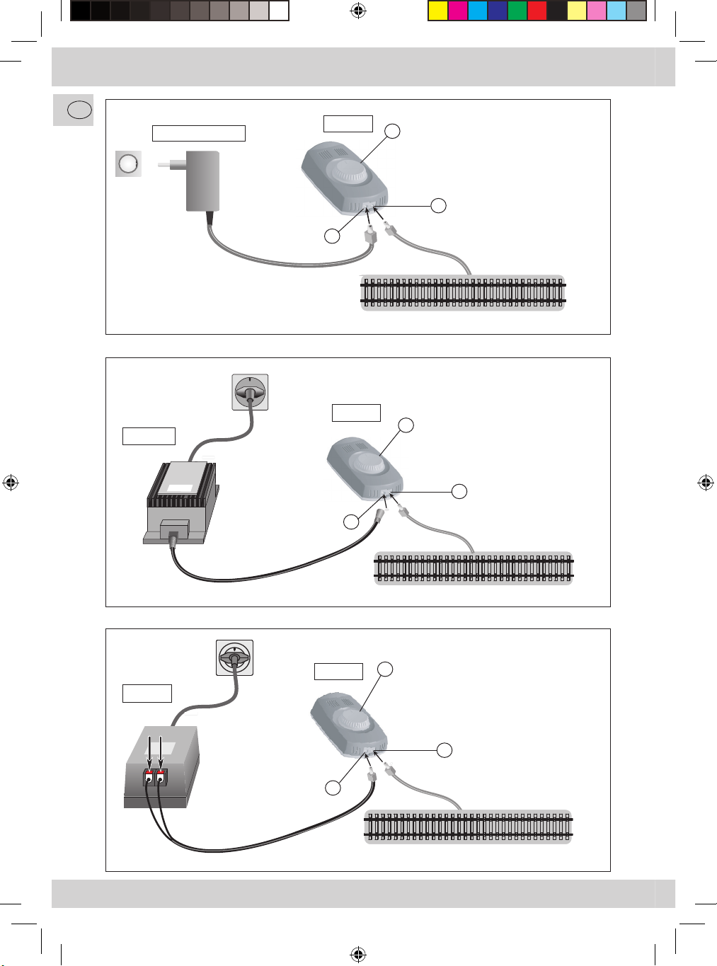
1. Prise «alimentation du régulateur»
Votre transformateur est à raccorder à cette prise (voir Fig.1-3).
2. Prise «sortie voie»
Cette prise est à relier avec la voie de votre réseau (voir Fig. 1-3).
3. Bouton régulateur
Par ce bouton vous allez déterminer la direction de marche et la vitesse de votre machine: De plus
que
vous vous éloignez de la position centrale, de plus la vitesse de la machine augmente. Le bouton
remis à la position centrale (position «0») le courant de traction est coupé et le régulateur est
électriquement déconnecté de votre réseau, sans que vous avez besoin de retirer la fiche de la prise
«sortie voie». Cette position sert également pour rear-mer le régulateur en cas que sa protection
électronique anti-court-circuit a déclenchée.
Application :
Alimentation du matériel moteur en courant continu «traction» régulé par variation de la lar-geur des
impulsions. Attention: Cette technique n’est pas appliquable à des modèles munis de moteurs à rotor
sans fer (Faulhaber, Escap, Canon et autres). Une utilisation de ce régulateur pour alimenter ces moteurs
peut causer une destruction de ces derniers.
Comme le régulateur ne dispose pas d’une séparation galvanique entre son «entrée ali-mentation» et
sa sortie «courant continu traction», il ne faut utiliser un seul et même transformateur pour plusieurs
régulateurs sauf si tous les engins moteurs de votre ré-seau sont alimentés exclusivement ou par la
voie ou par la caténaire! Une exploitation mixte (certaines machines alimentées par les rails, d’autres
par la caténaire) n’est pos-sible qu’en cas que chaque régulateur dispose de son transformateur indi-
viduel et ex-clusif. Une alimentation groupée (veut dire: alimentation de tous les régulateurs «voie»
par un transformateur et tous les régulateurs «caténaire» par un autre) risque de causer des influences
réciproques des deux groupes et donc des réactions imprévisibles des vé-hicules moteurs. Si votre
réseau est uniquement exploité par prise de courant par les rails ou par prise de courant par la caté-
naire, un transformateur peut alimenter sans problèmes plusieurs régulateurs à la fois, sous condition
que les différents cantons sont séparés l’un de l’autre par une isolation bipolaire (si votre réseau est
exploité unique-ment par prise de courant par la voie il faut deux éclisses, une au rail gauche et une
au rail droite de la voie, par sectionnement; s’il s’agit d’un réseau exploité uniquement par caténaire,
ensuite il faut une isolation supplémentaire dans la caténaire exactement au même endroit où se
trouvent les éclises isolantes dans les rails!).
8010727920 VII_2009 .indd 7 22.06.2011 11:06:18

8
F
Pannes éventuelles
L’alimentation du régulateur par le transformateur ne fonctionne pas.
Remède :
Pas de défaut au câblage reliant le transformateur au régulateur ?
La fiche du transformateur correctement enfichée dans la prise murale ?
Le disjoncteur de surcharge thermique a déclenché
Remède :
Remettre, d’abord, le bouton régulateur à la position centrale (position «0») et laisser en-suite
refroidir le régulateur. Avant de remettre en marche le régulateur, vérifier la charge électrique totale
du régulateur : il faut la réduire probablement.
La consommation en courant de traction par la locomotive et par des éclairages intérieurs éventuel-
lement installés dans vor voitures ne doit pas dépasser une charge maximale de 1,3 A.
Le disjoncteur électronique anti-court-circuit a déclenché
(uniquement en cas d’une alimentation par les transformateurs réf. 10718 ou 10725)
Remède :
Remettre le bouton régulateur à la position centrale (position «0»).
Avant de démarrer de nouveau chercher et supprimer la cause du court-circuit ayant déclenché le
disjoncteur électronique du régulateur !
En cas de court-circuit le régulateur alimenté par le transformateur réf. 801072711 avec fiche
intégrée se rechauffe légèrement jusqu’à ce que le disjoncteur thermique de surcharge coupe
le courant. Une fois le court-circuit supprimé, le disjoncteur se réenclenche automatiquement
au bout d’une quinzaine de secondes.
Caractèristiques Techniques;
Tension d‘alimententation Ue 15 V env. ( c.a ou c.d)
(Tension minimale admise: 13, 2 V ;
Tension maximale admise: 18 V)
Puissance absorbée
á vide Pv 0,4W env.
sous charge Pc 24W max.
Tension „traction“ Ut 0V à 18 Veff.
(Commande à variation de la
largeur des impulsions.)
Fréquence des impulsions
de la tension „traction“ 80 Hz environ
Tension résiduelle en
position neutre du bouton Ut 0V (sortie coupée et hors potentiel))
maximal admis It max.1,3A
8
8010727920 VII_2009 .indd 8 22.06.2011 11:06:18

I
9
REGOLATORE ELETTRONICO 10727
Attenzione:
il regolatore art. n° 10727 è stato ideato soprattutto per essere utilizzato insieme e con la spina art.
n° 8010727100. E’ possibile anche azionare la parte di regolazione 10727 con i trasformatori 10718 o
10725 (Fig. 1-3). Tuttavia in questo caso fare attenzione che, a causa della tensione di uscita maggiore, le
locomotive viaggiano troppo velocemente rispetto ai valori previsti.
Settore di utilizzo
Alimentazione di corrente ad ampiezza d’impulsi con regolazione della velocità uniforme per motrici in
corrente continua.
Inizio della funzione:
inizialmente il regolatore deve essere collegato con il trasformatore art. n° 10718, 10725 e con la spina
art. 8010727100, che lo alimenta in corrente alternata o continua 15V. Il regolatore trasmette alla presa
dei binari una tensione di avviamento una corrente continua ad ampiezza d’impulsi uniforme e regolabile
di un massimo di 18V (livello massimo degli impulsi) (Fig. 1-3).
1. Presa dell’alimentazione della tensione
Alla presa dell’alimentazione della tensione deve essere collegato il trasformatore (vedi ill. 1-3).
2. Presa dei binari
A questa presa deve essere collegato il binario (Fig. 1-3).
3. Manopola:
con essa viene selezionata la direzione di marcia della locomotiva e viene regolata la sua velocità in
modo uniforme: quanto più si gira la manopola allontanandola dalla posizione centrale, tanto più alta
è la velocità della locomotiva. Quando la manopola è in posizione centrale (posizione “0”), la corrente
è disinserita e il regolatore è separato elettricamente dall’impianto dei binari (e dalla linea aerea). La
manopola serve anche per fare il reset dopo un corto circuito.
Attenzione :
A causa del loro principio di regolazione, i regolatori di marcia ad impulso non sono adatti per motori con
indotto a campana senza ferro (ad esempio Fallhaber, Escap, Canon ed altri); l’uso di regolatori di marcia
ad impulso nei motori con indotto a campana può causare danni irreparabili a questo tipo di motore.
Il regolatore non dispone di una separazione galvanica incorporata tra l’entrata e l’uscita regolata della
corrente continua, possono essere collegati più regolatori ad uno stesso trasformatore, unicamente
se tutti i veicoli sul Vostro impianto vengono azionati o solo con una linea sotterranea o solo con una
linea aerea! Una mescolanza di linea sotterranea e linea aerea è possibile senza disturbi soltanto se
per ogni regolatore (indifferentemente se con linea sotterranea o con linea aerea) è a disposizione
un proprio trasformatore. L’alimentazione di corrente ad un gruppo (cioè tutti i regolatori per la linea
sotterranea ad un trasformatore e tutti i regolatori per la linea aerea ad un altro trasformatore) porta
con l’azionamento misto ad un’interferenza reciproca dei diversi circuiti di corrente e ad impreviste
reazioni dei veicoli. Nel puro azionamento con linea sotterranea o con linea aerea possono essere
collegati più regolatori ad un trasformatore comune (con un puro azionamento sotterraneo e la
congiunzione delle rotaie isolate rispettivamente nelle 2 rotaie di corsa, con il puro azionamento a
linea aerea in aggiunta anche nella linea aerea!).
8010727920 VII_2009 .indd 9 22.06.2011 11:06:19

I
10
Possibili guasti
L’ alimentazione dal trasformatore è interrotta
Rimedi:
la linea d’alimentazione dal trasformatore al regolatore è a posto?
La spina del trasformatore è nella presa?
L’interruttore di sicurezza per il sovraccarico termico ha reagito
Rimedi:
in primo luogo girare indietro la manopola nella posizione centrale e lasciare raffreddare
#il regolatore. Prima della rimessa in funzione, controllare il carico totale del regolatore ed
eventualmente ridurlo.
Il consumo di corrente da parte della/delle locomotiva/locomotive e l’illuminazione interna
non devono superare insieme 1,3 A.
Il dispositivo di sicurezza elettronico incorporato contro il corto circuito ha reagito
(Solo per alimentazioni superiori a 10718 o 10725.)
Rimedi:
girare indietro la manopola nella posizione centrale.
Prima di riavviare, cercare e rimuovere la causa del corto circuito!
Se durante il funzionamento si verifica un cortocircuito con la parte di rete dello spinotto
801072711, la parte di regolazione elettronica si scalda fino all’attivazione dell’interruttore
di sovraccarico termico o fino a quando viene rimosso il cortocircuito.
Dati Tecnici
Erogazione di tensione US ca.15 V (AC o DC)
(min. 13,2 V, max. 18 V)
Potenza assorbita
funzionamento a vuoto PL ca. 0,4 W
carico PS max. 24 W
Tensione d‘uscita UA 0V sino a 18 V
(Con funzionamento ad impulso.)
Frequenza dell‘impulso
della Tensione d‘uscita ca. 80 Hz
Posizione intermedia „0“ UA 0 V (senza potenziale)
Corrente in uscita IA max.1,3A
10
8010727920 VII_2009 .indd 10 22.06.2011 11:06:19

NL
11
Elektronische snelheidsregelaar 10727
Let op:
De Snelheidsregelaar 10727 is ontwikkeld voor gebruik in combinatie met en netspanningsnoer 8010727100.
Het is mogelijk dat de regelaar 10727 te gebruiken in combinatie met transformator 10718 of 10725 (zie afb.1-
3). Let erop dat door de hogere spanning de locomotieven sneller rijden dan u zou verwachten op basis van de
schaalverhouding.
Toepasbaarheid:
Impulsbreedte gestuurde rijstroomverzorging met traploze snelheidsregeling voor gelijkspanningslocomotieven
en -motorwagens.
In gebruik name:
De Snelheidsregelaar is voornamelijk aangesloten op Transformator 10718 of 10725 en netspanningsnoer
8010727100, die het met 15V wissel- of gelijkspanning voeden. Aan de railaansluiting zorgt de Snelheidsregelaar
voor een impulsbreedte gestuurde, traploos regelbare gelijkstroom-rijspanning van maximaal 18V (maximale im-
pulshoogte) (zie afb. 4).
1. Netspanningstekker
Aan de netspanningstekker aan de transformator aangesloten worden (zie afb.1-3).
2. Railaansluiting
Aan deze stekker wordt de rails aangesloten (zie afb.1-3).
3. Draaiknop:
Regelaar voor de rijrichting en traploze snelheid van de locomotieven: hoe verder de draaiknop vanaf het midden
wordt gedraaid, hoe hoger de snelheid van de locomotief. In de middenstand (0-stand) van de draaiknop is de
rijstroom uitgeschakeld en is de Snelheidsregelaar elektrisch van de rails gescheiden. Deze 0-stand dient men ook
te kiezen in geval van een kortsluiting op de rails.
Let op:
vanwege het regelingsprincipe zijn pulsbreedtegestuurde snelheidsregelaars niet geschikt voor klokankermotoren
zonder ijzeren ankel (zoals van Fallhaber, Escap, Canon en andere). Het gebruikt van deze apparatuur kan tot
onherstelbare schade leiden.
De Snelheidsregelaar beschikt niet over een galvanische scheiding tussen spanningsingang en de geregelde
gelijkspanningsuitgang. Gebruik van meerdere Snelheidsregelaars op een gemeenschappelijke transforma-
tor is alleen mogelijk als alle locomotieven via dezelfde manier stroom afnemen (dus alle via de wielen of
alle via de bovenleiding). Een gemengde stroomafname is alleen zonder storingen mogelijk als de Snel-
heidsregelaars elk van een eigen transformator worden voorzien. Een groepenstroomverzorging (meerdere
Snelheidsregelaars voor stroomvoorziening via de rails gevoed via een transformator en meerdere Snel-
heidsregelaars voor stroomvoorziening via de bovenleiding gevoed via een andere transformator) kan erin
resulteren dat de systemen elkaar beïnvloeden en storingen bij de locomotieven veroorzaken. Indien op
de modelspoorbaan uitsluitend via de rails of uitsluitend via de bovenleiding wordt gevoed kunnen wel
meerdere Snelheidsregelaars op een transformator worden aangesloten. Let op het aanbrengen van isolatie-
raillassen en scheiding van de bovenleiding!
8010727920 VII_2009 .indd 11 22.06.2011 11:06:19

NL
12
Mogelijke storingen
Stroomverzorging van de transformator is onderbroken.
Aanwijzing:
Snoer tussen transformator en Snelheidsregelaar in orde?
Transformatorstekker in de wandcontactdoos?
Thermische beveiliging geactiveerd.
Aanwijzing:
Draaiknop in 0-stand zetten en Snelheidsregelaar laten afkoelen. Voor ingebruikname de totale be-
lasting van de Snelheidsregelaar nakijken en eventueel verminderen.
Het stroomverbruik van de locomotieven en binnenverlichtingen mag niet meer dan 1,3A bedra-
gen.
Elektronische kortsluitingbeveiliging geactiveerd.
(uitsluitend in combinatie met 10718 of 10725)
Aanwijzing:
Draaiknop in 0-stand zetten.
Onderzoek de oorzaak van de kortsluiting op de modelbaan en los deze op voor het systeem weer
wordt belast.
In geval van een kortsluiting zal de thermische beveliging in werking treden tot de
kortsluiting wordt opgeheven.
Technische Specificatie
Ingangangsspanning US ca.15V (AC of DC)
(min. 13,2V, max. 18V)
Vermogensopname
onbelast PL ca. 0,4W
belast PS max. 24W
Uitgangsspanning UA 0V bis 18V
(impulsbreedte gestuurd)
Pulsfrequentie ca. 80 Hz
0-stand UA 0V (potentiaalvri)
Uitgangsstroom IA max.1,3A
12
8010727920 VII_2009 .indd 12 22.06.2011 11:06:19

13
F
Anschlusskombinationen
Nur an den Leistungsfähigen Transformatoren 10725 oder 10718 kann mehr als ein Regelteil 10727
betrieben werden. Unter durchschnittlichen Betriebsbedingungen sind jedoch max. 4 bis 5 Regler zu
empfehlen. Die Fahrstromkreise sind gegeneinander unbedingt auf beiden Schienenprofilen zu trennen.
Beim Anschluss des doppelpoligen Anschlusskabel ans Gleis ist die Orientierumg des Drehreglers mit der
gewünschten Fahrtrichtung der Lok abzugleichen
Zulässige und unzulässige Schaltungen
Permissible and non-permissible circuits
Câblages admises et à éviter
Collegamenti ammessi e non ammessi
Fig.4
8010727920 VII_2009 .indd 13 22.06.2011 11:06:20

14
F
Connection combinations
Only on the efficient transformers 10725 or 10718 is it possible to operate one or more control units
10727. A maximum of 4 to 5 controllers are however recommend under average conditions. It is indis-
pensable to isolate the drive circuits on both rail profiles. When connecting the double-pole connection
cable to the track the orientation of the rotary controller must be coordinated with the desired travelling
direction of the locomotive.
Combinaisons possibles de raccordement
Vu sa puissance, le transformateur avec fiche intégrée ne peut alimenter qu’un seul régulateur électroni-
que à la fois; par contre les transformateurs réf. 10725 et 10718 qui – grâce à leurs puissances sensib-
lement plus élevées – peuvent alimenter jusqu’à 4 ou 5 régulateurs sous des conditions d’exploitation
habituelles aux petits et moyens réseaux domestiques (des trains lourds ou avec des voitures éclairées
imposent une réduction du nombre de régulateurs par transformateur). Les différents circuits électriques
de traction (cantons électriques) sont à séparer l’un de l’autre par des isolations bipolaires (éclisses
isolantes dans les deux rails d’une voie; isolation de la caténaire au même endroit, s’il y a une ligne
aérienne...). Très important : Si vous raccordez le régulateur à la voie par le câble bipolaire, il faut syn-
chroniser le régulateur avec la direction de marche de la locomotive : Si la machine circule en contre-sens
par rapport à la position du bouton du régulateur, il faut permuter les deux fils du câble bipolaire.
Combinazioni di allacciamento
Solo per i trasformatori ad elevate prestazioni 10725 o 10718 è possibile azionare più di una parte
di regolazione 10727. Tuttavia in condizioni di esercizio normali si consiglia l’uso di 4-5 regolatori al
massimo. I circuiti della corrente di marcia devono essere assolutamente separati l’uno dall’altro su
entrambi i profili delle rotaie. Durante l’allacciamento al binario del cavo di allacciamento bipolare, è
necessario compensare l’orientamento dell’encoder rotativo con la direzione di marcia desiderata per la
locomotiva.
Aansluitcombinaties
Er kunnen aan de trnasformatoren 10718 en 10725 meerdere regelaars 10727 worden aangesloten. Onder
normale omstandigheden dient het het aantal te beperken tot maximaal 4 tot 5 stuks. De stroomkringen
zijn door middel van isolatie met raillassen volledig te scheiden. Door de aansluiting van de dubbelpolige
aansluitkabel om te draaien kunt u de rijrichting van locs laten overeenstemmen met de draairichting van
de regelaa.
14
8010727920 VII_2009 .indd 14 22.06.2011 11:06:20

15
8010727920 VII_2009 .indd 15 22.06.2011 11:06:20

Änderungen von Konstruktion und Ausführung
vorbehalten! • We reserve the right to change the
construction and design! • Nous nous réservons
le droit de modifi er la construction et le dessin! •
Ci riserviamo il diritto di variare la costruzione e il
design! • Verandering van model en construcie
voorbehounden.
Bitte diese Beschreibung zum späteren Gebrauch
aufbewahren! • Please retain these instructions
for further reference! • Pi�re d‘bien vouloir con-
server ce mode d’emploi en vue d’une future utili-
sation! • Conservate queste istruczioni per un futu-
ro utiliozzo! • Deze handleding altijd bewaren.
Modelleisenbahn GmbH
Plainbachstraße 4
A - 5101 Bergheim
Tel.: +43 (0)5 7626
8010727820 VI / 2011
8010727920 VII_2009 .indd 16 22.06.2011 11:06:21
Table of contents
Languages:
Other roco Control Unit manuals
Popular Control Unit manuals by other brands

Allen-Bradley
Allen-Bradley ControlLogix DeviceNet C Series installation instructions

Dungs
Dungs MB-ZR B07 Series instructions

HP
HP 6600-A FIP-600 FlexIntfPltfrm Rtr Mod Product End-of-Life Disassembly Instructions

Allen-Bradley
Allen-Bradley 1492-CM1771-LD008F installation manual

Lenze
Lenze E94AYFLF Mounting instructions

Immergas
Immergas MAGIS PRO 5 ERP Instruction and recommendation booklet