Doosan D50S-5 User manual

Power Train
Specification
System Operation
Testing & Adjusting
Disassembly & Assembly
D50S-5, D60S-5, D70S-5, D80S-5, D90S-5
G50S-5, G60S-5, G70S-5
Two Speed Transmission
Drive Axle (OCD , SHOE)
SB4274E00
Sep. 2007

1
Important Safety Information
Most accidents involving product operation, maintenance and repair are caused by failure to observe basic
safety rules or precautions. An accident can often be avoided by recognizing potentially hazardous situations
before an accident occurs. A person must be alert to potential hazards. This person should also have the
necessary training, skills and tools to perform these functions properly.
Improper operation, Iubrication, maintenance or repair of this product can be dangerous and could
result in injury or death.
Do not operate or perform any Iubrication, maintenance or repair on this product, until you have read
and understood the operation, Iubrication, maintenance and repair information.
Safety precautions and warnings are provided in this manual and on the product. If these hazard warnings are
not heeded, bodily injury or death could occur to you or other persons.
The hazards are identified by the "Safety Alert Symbol" and followed by a "Signal Word" such as "WARNING"
as shown below.
The meaning of this safety alert symbol is as follows :
Attention! Become Alert! Your Safety is Involved.
The Message that appears under the warning, explaining the hazard, can be either written or pictorially
presented.
Operations that may cause product damage are identified by NOTICE labels on the product and in this
publication.
DOOSAN cannot anticipate every possible circumstance that might involve a potential hazard. The warnings
in this publication and on the product are therefore not all inclusive. If a tool, procedure, work method or
operating technique not specifically recommended by DOOSAN is used, you must satisfy yourself that it is
safe for you and others. You should also ensure that the product will not be damaged or made unsafe by the
operation, Iubrication, maintenance or repair procedures you choose.
The information, specifications, and illustrations in this publication are on the basis of information available at
the time it was written. The specifications, torques, pressures, measurements, adjustments, illustrations, and
other items can change at any time. These changes can affect the service given to the product.
Obtain the complete and most current information before starting any job. DOOSAN dealers have the most
current information available.
WARNING


Power Train Index3
Index
Specification
General Tightening Torque ...................................5
Drive Axle Specification........................................6
Torque Converter..................................................7
Transmission Pump..............................................7
Drive Axle Mounting..............................................8
Differential ............................................................8
Wheel Bearing and Drive Wheel ...........................8
Brake Assembly....................................................9
Brake Drum Diameter.........................................10
U - joint...............................................................10
System Operation
General Information............................................11
Power Shift Transmission....................................12
General Information.........................................12
Power Flow at Low Speed Forward..................13
Power Flow at High Speed Forward.................14
Power Flow at Low Speed Reverse..................15
Power Flow at High Speed Reverse.................16
Transmission Control Valve................................17
Cross-Section View..........................................17
Hydraulic Schematic........................................18
Differential and Drive Axles.................................20
Differential .......................................................20
Wheel Hub.......................................................20
Brake Components.............................................21
Shoe Brake......................................................21
Brake Adjuster.................................................21
OCDB..............................................................22
Testing and Adjusting
Troubleshooting..................................................23
Visual Checks..................................................23
Checks During Operation.................................23
Check List During Operation ............................23
Check List From Operation Noise.....................25
Check List From Pressure Test........................26
Differential .......................................................27
Transmission Pressure.......................................28
Converter Stall Test............................................29
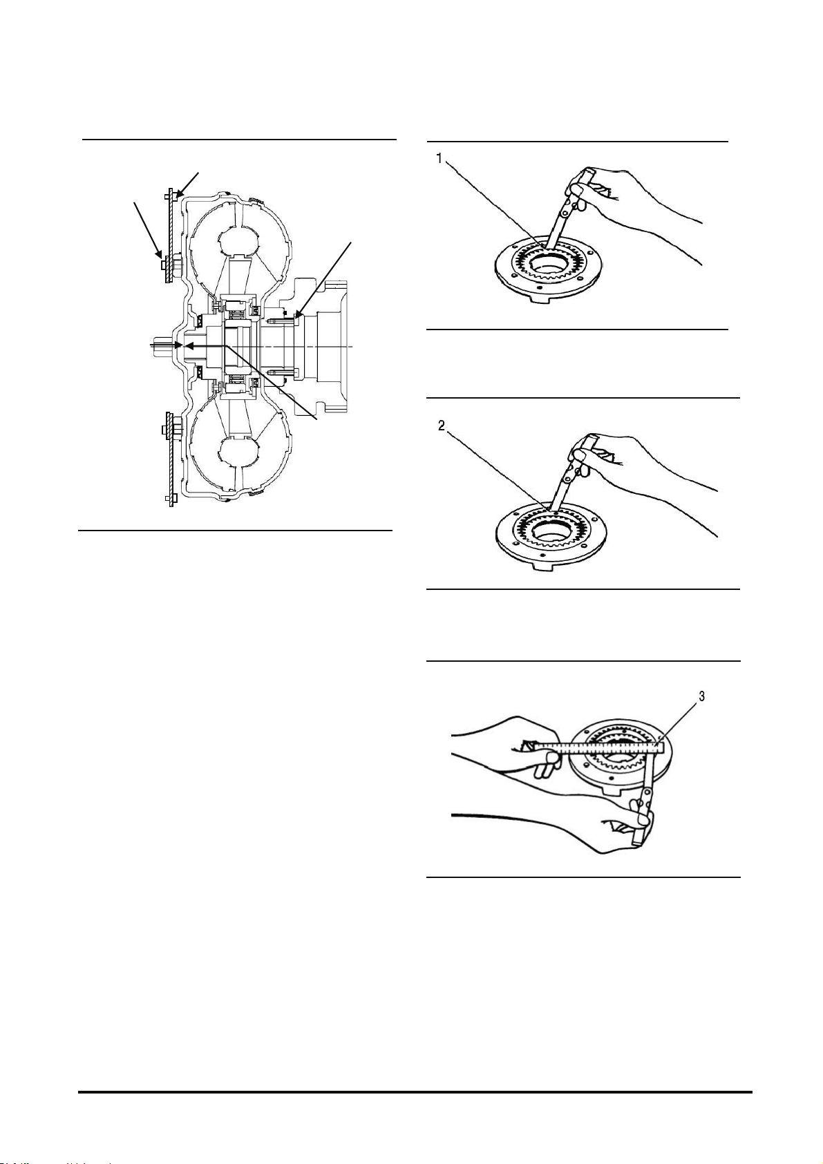
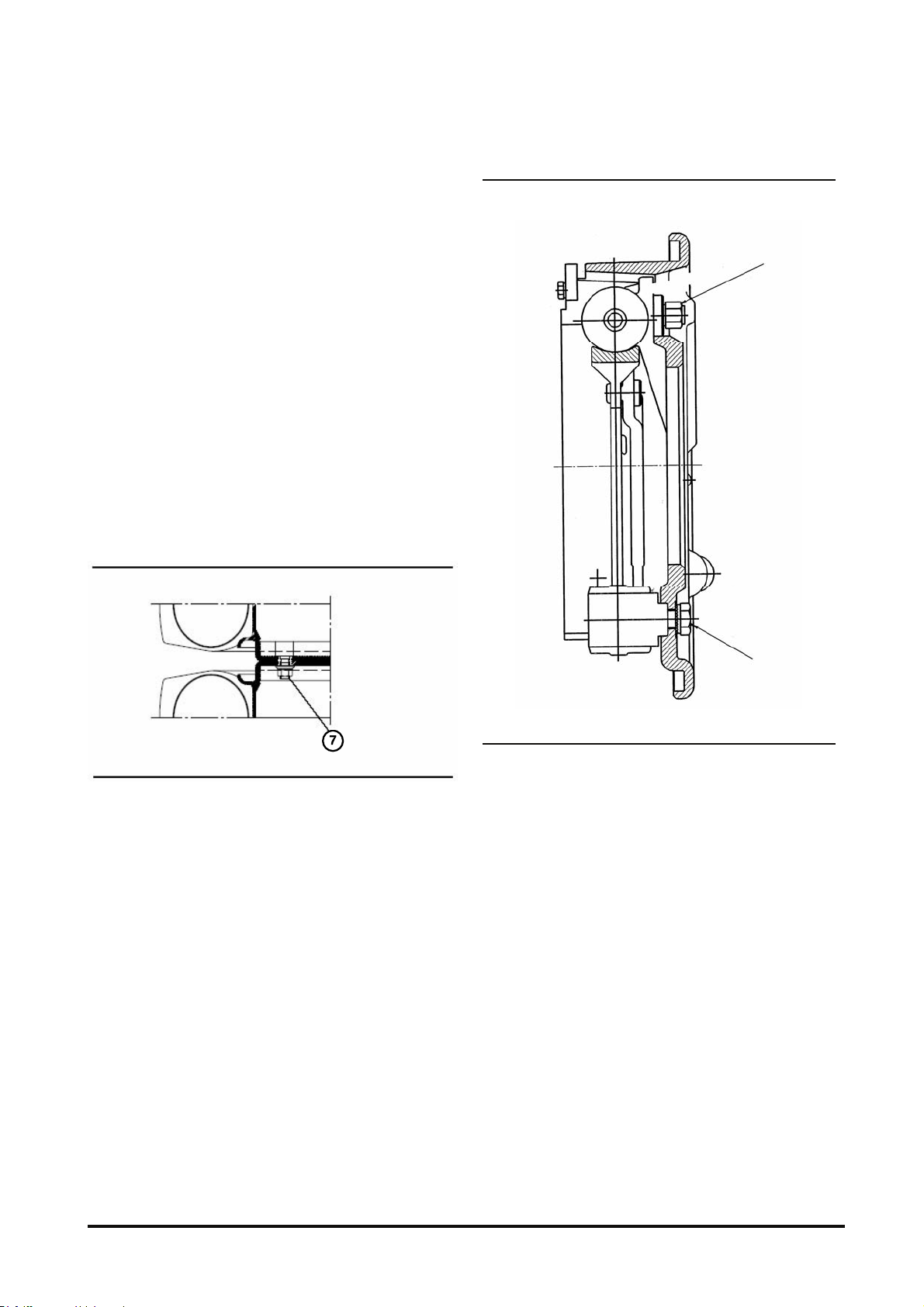
Shimming of Transmission Shaft.........................30
Wheel Brake Adjustment.....................................30
Inching Pedal Adjustment....................................32
Disassembly and Assembly
Drive Shaft and Universal Joint............................35
Engine, Torque Converter and Transmission.......36
Transmission Control Valve.................................40
Transmission.......................................................43
Drive Axle ...........................................................54


Power Train Specification5
Specification
General Tightening Torque
GENERAL TIGHTENING TORQUE FOR
BOLTS, NUTS AND TAPERLOCK STUDS
The following charts give the standard torque values for bolts, nuts
and taperlock studs of SAE Grade 5 of better quality. Exceotions
are given in other sections of Service Manual where needed.
THREAD DIAMETER STANDARD TORQUE
inches millimeters lb•ft. N•m*
Standard thread
Use these torques for bolts and nuts with standard
threads (conversions are approximate).
1/4 6.35 9 ± 3 12 ±4
5/16 7.94 18 ±5 25 ±7
3/8 9.53 32 ±5 45 ±7
7/16 11.11 50 ±10 70 ±15
1/2 12.70 75 ±10 100 ± 15
9/16 14.29 110 ±15 150 ±20
5/8 15.88 150 ±20 200 ±25
3/4 19.05 265 ±35 360 ±50
7/8 22.23 420 ±60 570 ±80
1 25.40 640 ±80 875 ±100
1 1/8 28.58 800 ±100 1100 ±150
1 1/14 31.75 1000 ±120 1350 ±175
1 3/8 34.93 1200 ±150 1600 ±200
1 1/2 38.10 1500 ±200 2000 ±275
Use these torques for bolts and nuts on hydraulic
valve bodies.
5/16 7.94 13 ±2 20 ±3
3/8 9.53 24 ±2 35 ±3
1/16 11.11 39 ±2 50 ±3
1/2 12.70 60 ±3 80 ±4
5/8 15.88 118 ± 4 160 ±6
Taperlock stud
Use these torques for studs with Taperlock threads
1/4 6.35 6 ±2 8 ±3
5/16 7.94 13 ±4 17 ±5
3/8 9.53 26 ±4 35 ±5
7/16 11.11 33 ±7 45 ±10
1/2 12.70 48 ±7 65 ±10
9/16 14.29 65 ±11 90 ±15
5/8 15.88 80 ±11 110 ±15
3/4 19.05 125 ±15 170 ±20
7/8 22.23 190 ±22 260 ±30
1 25.40 300 ±30 400 ±40
1 1/8 28.58 370 ±30 500 ±40
1 1/4 31.75 480 ±37 650 ±50
1 3/8 34.93 550 ±37 750 ±50
1 1/2 38.10 640 ±37 870 ±50
*1 newton meter(N•m) is approximately the same as 0.1 mkg.

Power Train Specification6
Drive Axle Specification
Shoe Type
Differential 2.636 / D(G) 50/70S-5
3.100 / D80/90S-5
Planetary 4
Gear Ratio
Total 10.545 / D(G) 50/70S-5
12.400 / D80/90S-5
Axle Oil SAE #80 or #90
Drive Axle
Oil Volume 12.5 L
Service Brake Shoe Brake
Brake Oil AZOLLA - ZS10
Brake
Parking Brake Drum Brake
Gear Type Spiral Bevel Gear
Differential Differential Type 4 Pinions
OCDB Type
Differential D(G)50/70S-5 : 2.636
D80/90S-5 : 3.100
Planetary 4
Gear Ratio
Total D(G)50/70S-5 : 10.545
D80/90S-5 : 12.400
Axle Oil MOBIL #424
Drive Axle
Oil Volume 12.5 L
Service Brake Oil Cooled Disk Brake
Brake Oil AZOLLA - ZS10
Brake
Parking Brake Drum Brake
Gear Type Spiral Bevel Gear
Differential Differential Type 4 Pinions

Power Train Specification7
Torque Converter
(1) Torque for bolts (plate to torque converter)
.....................................45 ± 7 N∙m (33 ± 5 lb•ft)
Apply LOCTITE NO. 277 sealant to threads of
bolts.
(2) Torque for bolts (plate to flywheel)
.....................................25 ± 7 N•m (18 ± 5 lb•ft)
(3) End play of turbine hub (new) .
............................... 0 to 0.99 mm (0 to 0.039 in)
Maximum end play of turbine hub (worn)
.............................................1.65 mm (0.065 in)
(4) Torque for bolts (torque converter to PTO gear)
.....................................20 ± 3 N•m (15 ± 2 lb•ft)
Apply LOCTITE NO. 277 sealant to threads of
bolts.
NOTE : For Torque values not given, see the page
of specifications for general tightening torques.
Transmission Pump
(1) Clearance between outside of drive gear and
crescent 0.36 to 0.43 mm (0.014 to 0.017 in)
(2) Clearance between inside of driven gear and
crescent 0.25 to 0.33 mm (0.010 to 0.013 in)
(3) Gear end play....................... 0.025 to 0.064 mm
(0.0010 to 0.0025 in)
4
1
2
3

Power Train Specification8
Drive Axle Mounting
(1) Torque for nuts.....800 ± 50 N•m (590 ± 37 lb•ft)
Apply LOCTITE NO. 271 sealant to threads of
bolts.
Differential
1. Apply Loctite No.271 to threads of bolt. Torque
for bolts that hold bevel gear to differential
housing is....................132 ± 5 N•m (98 ± 4 lb•ft).
2. Apply Loctite No.271 to threads of bolts. Torque
for bolts is......................59 ± 5 N•m (43 ± 4 lb•ft).
3. Apply Loctite No.271 to threads of bolts.
Torque for bolts.......... 157 ± 5 N•m (116 ± 4 lb•ft)
Consider same marking on brackets to the
housing.
4. Apply Loctite No.271 to threads of bolts.
Torque for bolts................10 ± 2 N•m (7 ± 2 lb•ft)
5. Apply Loctite No.271 to threads of bolts.
Torque for bolts.......... 177 ± 5 N•m (130 ± 4 lb•ft)
6. Torsional backlash of bevel gear...0.18~0.23 mm
Wheel Bearing and Drive Wheel
Shoe Axle
OCDB Axle

Power Train Specification9
Slotted nut adjustment
a. Tighten slotted nut (1) slightly by hand.
b. Tighten slotted nut (1) to 640 N•m (472 lb•ft).
c. Rotate wheel hub several times.
d. Turn back slotted nut (1) slightly and retighten
until bearing friction torque reaches to 10~14
N•m (7.4 to 10.3 lb•ft).
e. Apply Loctite No.271 on the threads of bolt (2).
Secure slotted nut (1) with bolt (2) with tightening
torque of 19~24 N•m (14~18 lb•ft).
f. Assemble thrust washer (3) with Loctite # 609.
g. Torque for Spindle bolt (5) ...............118 ± 5 N•m
(87 ± 4 lb•ft)
h. Torque for Service piston bolt (6) ....15 ± 0.1 N•m
(11 ± 0.01 lb•ft)
i. Torque for wheel nut (7)................550 ± 50 N•m
(406 ± 37 lb•ft)
Brake Assembly
Torque for bolts (1).......19 to 22 N•m (14 to 16 lb•ft)
Torque for bolts (2)...... 120 ± 20 N•m (90 ± 15 lb•ft)
ICPS0005S
1
2

Power Train Specification10
Brake Drum Diameter
Brake drum diameter (1)............315.0 to 315.2 mm
(12.402 to 12.409 in)
Maximum total diameter of brake drums which can
be machined from the original diameter....... 2.0 mm
(0.079 in)
U - joint
Torque for bolts (1) ................................55 ± 7 N•m
(40 ± 5 lb•ft)
(1)
(1)

Power Train System Operation11
System Operation
General Information
(1) Engine (2) Torque Converter (3) Power Shift Transmission (4) Universal joint (5) Drive Axle (6) Drive Wheels.
The basic components of the power train are:
engine (1), torque converter (2), power shift
transmission (3), universal joint (4), drive axle (5),
drive wheels (6).
Power from the engine flywheel goes from the
torque converter to the input shaft of the
transmission. The power shift transmission is a
constant mesh countershaft type and has four
hydraulically operated clutches that are spring
released. The transmission has two speeds in
forward and two speeds in reverse.
Power from the transmission is sent through its
output gear through the drive shaft and reduction
gears to the differential. The differential sends
power out the axles and to the wheels.
NOTICE
Damage can be caused to the transmission if the
truck is moved with the engine not running. There
will be no lubrication to the transmission
components. Disconnect and remove the universal
joint before the truck is moved.

Power Train System Operation12
Power Shift Transmission
General Information
The transmission is a constant mesh power shift
transmission and gives two forward and two
reverse speeds. The transmission has four
clutches that are engaged hydraulically and
released by spring force. The direction and speed
are changed electrically.
Power Shift Transmission
(1) Input Shaft. (2) Cylinder Clutch(Forward)
(3) Cylinder Clutch(Reverse). (4) Reverse Shaft.
(5) Gear(Reverse low) (6) Clutch(Reverse low).
(7) Piston. (8) Clutch(Reverse high).
(9) Gear(Reverse high). (10) Intermediate Shaft.
(11) Gear(low). (12) Intermediate Shaft Gear.
(13) Gear(High) (14) Output Shaft. (15) Output Shaft Gear.
(16) Clutch(Forward low) (18) Valve Ass’y. (19) Yoke.
(20) Gear(Forward high). (21) Clutch(Forward high).
(22) Gear(Forward low).
In the power flow diagrams that follow, the
components are shown in a position to make it
easier to follow the power flow through the
transmission. Illustration shows the transmission
from the converter end with the correct location of
the components.
(2) Clutch Gear. (3) Clutch Gear. (5) Gear(Reverse low).
(9) Gear(Reverse high). (10) Intermediate Shaft Gear.
(11) Gear(Low). (13) Gear(High). (14) Output Shaft Gear.
(20) Gear(Forward high). (22) Gear(Forward low).
Most all of the components inside the transmission
turn when the controls are in either of the
FORWARD or REVERSE speeds. Only those
components that have been made dark in the
diagrams that follow are used in the flow of power
through the transmission.
ICPS044S
22
9
10
11
13
20
A
B
2
3
5
14
B
A
A
A
A
B
B
B
B

Power Train System Operation13
Power Flow at Low Speed Forward
Power Flow In Low Speed Forward
(1) Input Shaft. (2) Cylinder Clutch(Forward). (7) Piston. (10) Intermediate Shaft. (11) Gear(Low). (12) Intermediate Shaft Gear.
(13) Gear(High). (14) Output Shaft. (15) Output Shaft Gear. (16) Clutch(Forward low). (18) Valve Ass’y (19) Yoke.
(20) Gear(Forward high). (21) Clutch(Forward high). (22) Gear(Forward low).
Input shaft (1) of the transmission is turned by the
turbine of the torque converter. The clutch cylinder
(2) for the forward clutches is connected to the input
shaft by rivets.
When FORWARD low clutch (16) is engaged, gear
(22) is turned through the clutch. Gear (22) is
engaged with gear (11) and turns gears (11) and
(13) gears (11) and (13) are both connected to shaft
(10) by splines. Shaft (10) is engaged with output
shaft gear (15) by intermediate shaft gear (12). This
sends the power from shaft (10) through output
shaft gear (15) into output shaft (14) of the
transmission.
SECTION : A-A

Power Train System Operation14
Power Flow at High Speed Forward
Power Flow In High Speed Forward
(1) Input Shaft. (2) Cylinder Clutch(Forward). (7) Piston. (10) Intermediate Shaft. (11) Gear(Low). (12) Intermediate Shaft Gear.
(13) Gear(High). (14) Output Shaft.. (15) Output Shaft Gear. (16) Clutch(Forward low). (18) Valve Ass’y (19) Yoke.
(20) Gear(Forward High). (21) Clutch(Forward High). (22) Gear(Forward low).
Input shaft (1) of the transmission is turned by the
turbine of the torque converter. The clutch cylinder
(2) for the forward clutches is connected to the input
shaft by rivets.
When FORWARD high clutch (21) is engaged, gear
(2) is turned through the clutch. Gear (20) is
engaged with gear (13) and turns gears (13) and
(11) gears (13) and (11) are both connected to shaft
(10) by splines. Shaft (10) is engaged with output
shaft gear (15) by intermediate shaft gear (12). This
sends the power from shaft (10) through output
shaft gear (15) into output shaft (14) of the
transmission.
SECTION : A-A

Power Train System Operation15
Power Flow at Low Speed Reverse
Power Flow In Low Speed Reverse
(1) Input Shaft. (2) Clutch Cylinder Gear(Forward). (3) Clutch Cylinder Gear(Reverse). (4) Reverse Shaft. (5) Gear(Reverse
low). (6) Clutch(Reverse low). (7) Piston. (8) Clutch(Reverse high). (9) Gear(Reverse high). (10) Intermediate Shaft.
(11) Gear(Low). (12) Intermediate Shaft Gear. (13) Gear(High). (14) Output Shaft. (15) Output Shaft Gear. (18) Valve Ass’y.
(19) Yoke.
Input shaft (1) of the transmission is turned by the
turbine of the torque converter. The clutch cylinder
(2) for the forward clutches is connected to the input
shaft by rivets. Clutch cylinder (2) is engaged with
and turns clutch cylinder (3).
When REVERSE low clutch (6) is engaged, gear (5)
is turned through the clutch. Gear (5) is engaged
with gear (11) and turns gears (11) and (13) gears
(11) and (13) are both connected to shaft (10) by
splines. Shaft (10) is engaged with output shaft gear
(15) by intermediate shaft gear (12). This sends the
power from shaft (10) through output shaft gear (15),
into output shaft (14) of the transmission.
SECTION : B-B

Power Train System Operation16
Power Flow at High Speed Reverse
Power Flow In High Speed Reverse
(1) Input Shaft. (2) Clutch Cylinder Gear(Forward). (3) Clutch Cylinder Gear(Reverse). (4) Reverse Shaft.
(5) Gear(Reverse low). (6) Clutch(Reverse low). (7) Piston. (8) Clutch(Reverse high). (9) Gear(Reverse high).
(10) Intermediate Shaft. (11) Gear(Low). (12) Intermediate Shaft Gear. (13) Gear(High). (14) Output Shaft.
(15) Output Shaft Gear. (18) Valve Ass’y. (19) Yoke
Input shaft (1) of the transmission is turned by the
turbine of the torque converter. The clutch cylinder
(2) for the forward clutches is connected to the input
shaft by rivets. Clutch cylinder (2) is engaged with
and turns clutch cylinder (3).
When REVERSE high clutch (8) is engaged, gear
(9) is turned through the clutch. Gear (9) is engaged
with gear (13) and turns gears (13) and (11) gears
(13) and (11) are both connected to shaft (10) by
splines. Shaft (10) is engaged with output shaft gear
(15) by intermediate shaft gear (12). This sends the
power from shaft (10) through output shaft gear (15),
into output shaft (14) of the transmission.
SECTION : B-B

Power Train System Operation17
Transmission Control Valve
Cross-Section View
(1) BODY. (2) SPOOL. (3) SPRING. (4) PLUG. (5) O-RING. (6) ORIFICE. (7) STOPPER. (8) O-RING. (9) SPRING.
(10) PISTON. (11) PLUG. (12) FILTER ASS'Y. (13) O-RING. (14) SPOOL. (15) SPRING. (16) SPRING. (17) PLUNGER.
(18) PIN. (19) STOP BOL (20) OIL SEAL. (21) PLUG. (22) O-RING. (23) PLUG. (24) O-RING. (25) SOLENOIDE VALVE ASS'Y.
(26) PLUG. (27) O-RING. (28) BS CONNECTOR ASS'Y. (29) GASKET. (30) O-RING. (31) SPRING. (32) PLATE. (33) PISTON.
(34) GASKET.
SECTION "B-B"
RELIEF VALVE INCHING VALVE
ACCUMULATOR
VALVE
SOLENOID VALVE
F1 F2 R1 R2
F1 F2 R1 R2
F1F2R1R2

Power Train System Operation18
Hydraulic Schematic
(1) RELIEF VALVE. (2) INCHING VALVE. (3) ACCUMULATOR VALVE. (4) SOLENOID VALVE.
(1) RELIEF VALVE
◆FUNCTION
To maintain constant pressure in the CONTROL
VALVE, preventing excessive rise or fall of
pressure, and supply oil to TORQUE
CONVERTER.
◆OPERATION
The oil from the PUMP is fed to VALVE via “A.”
As pressure rises, the oil through “A” overcomes
the spring force and pushes SPOOL to left.
When the SPOOL is pushed to left by oil
pressure, “A” and “B” are connected and the oil
from “A” enters TORQUE CONVERTER through
“B” and pressure falls.
When the pressure fell, PISTON returns reducing
the inflow to the TORQUE CONVERTER, raising
pressure again. The minimum pressure is
maintained by the repeated operation of the
SPOOL.
In the event that the pressure is keep rising when
oil flows to TORQUE CONVERTER, SPOOL is
pushed to right, and at the preset pressure, the
oil entered through “A” is drained through “C”
preventing the pressure rise higher than the
preset value.

Power Train System Operation19
(2) INCHING VALVE
◆FUNCTION
The INCHING VALVE controls the pressure of oil
entering CLUTCH and smoothens the CLUTCH
contact.
In addition, by enabling the vehicle to move
smoothly at high RPM, it provides fast
functionality of the implement in low speed.
◆OPERATION
When the INCHING PEDAL is not pressed, the
oil from the main pressure line "A" is fed to
ACCUMULATOR VALVE through valve and “D.”
When the INCHING PEDAL is pressed, SPOOL
moves toward left, isolating the main pressure
line "A" stopping oil supply. The oil in the
ACCUMULATOR is drained through “C” via “D”
lowering pressure at CLUTCH.
(3) ACCUMULATOR VALVE
◆FUNCTION
Smoothens CLUTCH operation by enlarging the
time for pressure rise since from the CLUTCH
contact and beginning of slip.
◆OPERATION
When the INCHING PEDAL is pressed and let
free, oil enters “E(1st orifice)” from inching to
move piston to right. Then, pressure rises slowly
to open “F(2nd orifice).” When the piston reaches
right side, pressure rises up to the relief setting
value.
In the oil path of the accumulator valve plug to
solenoid valve is #100 screen which filters
foreign material.
Therefore, wash the plug when replacing the T/M
oil.
(4) SOLENIOD VALVE
◆FUNCTION
Supplies the oil from accumulator to each clutch
according to the change of step.
◆OPERATION
When the shift lever is moved, the spool in the
solenoid valve moves toward bottom by electric
signal, forming oil path.
The oil from accumulator enters “G”, flows
through the internal path of solenoid valve, and
fed to clutch via “H.”
When the shift lever is at neutral position, the
electric signal us cut-off, the spool moves
upwards by the force of the spring in the solenoid
valve, forming an oil path from “G” to “C(tank)”
removing residual pressure in the clutch.
Other manuals for D50S-5
2
This manual suits for next models
7
Table of contents
Other Doosan Control Unit manuals
Popular Control Unit manuals by other brands

Multitech
Multitech MultiConnect Dragonfly MTQ-MNA1-B02 Device guide

Ublox
Ublox C101-D9C user guide

Bitron Video
Bitron Video Domular Classic PSM70 Evolution manual

ATECH
ATECH BCV 700 Installation and operating instructions

Alfalaval
Alfalaval SRC PN10 instruction manual

Alfalaval
Alfalaval Unique 7000 Series instruction manual