Profort multiGuard DIN4 User manual
QUICK GUIDE for 4 modules
www.profort.com
Pg. 1
Installation
1. Prepare a SIM card so that the PIN code is 1234 or is deactivated. Mount the card in the unit. The
unit has now 1234 as password or runs without a password. The card must be placed as shown
below.
2. Connect inputs, outputs and power cable (12-24 VAC/DC) and if necessary a rechargeable 3,6 V Li-
ion battery.
3. Turn on the power. A red diode is lit. After max. 1 min. the diode flashes approx. every 2 sec., and
the unit is ready.
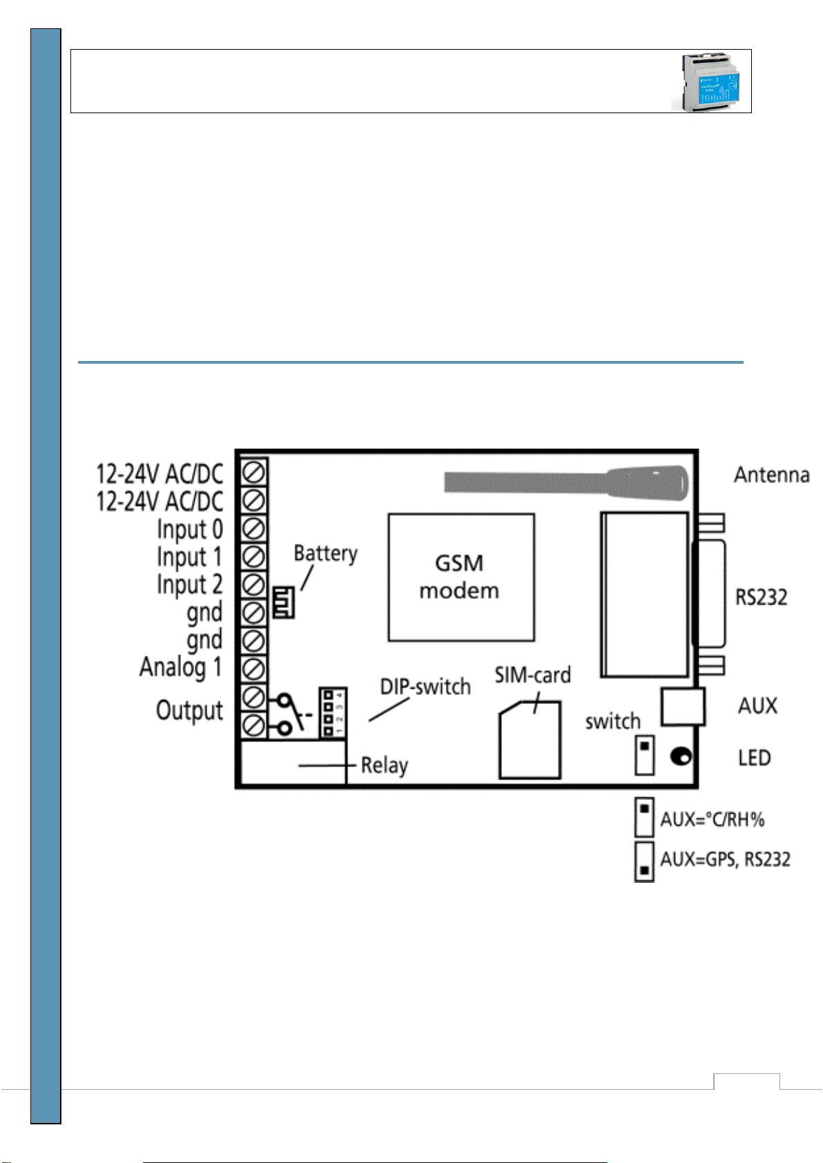
The GSM unit interior
DIP-switch for analog input
1 ON: 0-10 VDC
2 ON: 0/4-20 mA
3 ON: PT-100
4 ON: Profort probes
All OFF: digital input
Voltage
Output: AC max. 230 VAC, 6A
DC max. 30 VDC, 6A
Input, digital: max. 24 VDC
max. power 2 mA
Input, analog: max. 0-10 VDC
Only print voltage when
The DIP-switch 1 is on, and 2-4
are off

SET-UP - MANAGEMENT
.Version 3.16
Pg. 2
Set-up on PC via the PC COM-port
1. Connect the device to the PC COM port with an RS-232 cable or USB-RS232 converter (the
converter driver must be installed)
2. Install Profort PC software on a computer with Windows by downloading the program from
www.profort.dk. Start the program and enter the product key specified on the page.
3. Enter the number of the COM port the PC is using
4. Complete the rest of the setup program and end by transferring the information to the device
Additional help: press F1 in the program, see the manual on the CD or www.profort.com
Set-up via masterView
1. Open a browser on your PC, tablet or smartphone.
2. Type http://setup.masterview.dk in the address bar, and choose ’setup’(or login via
www.profort.dk). Log on to the portal or create yourself as user. An unlimited number of units can
be connected to any user, and several users can be connected to the same units.
3. Create a new unit in the list and choose multiGuard DIN4 as unit. When you press SAVE the portal
sends a text message to the unit, which connects it to the Profort server via GPRS/Internet on the
SIM-card. The USERNAME of the unit will now be its telephone number (to be used, if controlling
the unit via the Profort app). All communication will then take place as data.
4. Type in the required information and press ‘send and save’.
5. The unit is now ready to use.
QUICK GUIDE for 4 modules
www.profort.com
Pg. 3
Set-up with text message
1234 = password, 0 = zero, space counts as a character and is therefore important.
Define the unit
phone number and
change password, if
necessary. Add ID
text.
1234 N0 88888888 yyyy
ID text
(N0 = N + zero)
1234=current password, N0, 88888888= the unit
mobile no.
yyyy = new four-digit password.
ID text: First text in all messages from unit (max.
32 characters).
Receivers
Add
1234 N1 11111111
1234 N2 11111111 *
Adds receiver 11111111 in space no. 1 to receive
alarm as text message.
Adds receiver 11111111 in space no. 2 to receive
alarm as call with tones.
Further spaces (25 in all):
N2..N9, NA (10), NB (11) .. NP (25),.
Delete
1234 N1
Deletes receiver in space no. 1
Text on input
Add
1234 A0 OPEN TEXT
TEXT on input 0 by open/break. x = (A0…A2)
1234 L0 CLOSE TEXT
TEXT on input 0 by close/make. (L0..L2)
Delete
1234 A0
Deletes TEXT for input 0 by open/break.
(A0..A2)
1234 L0
Deletes TEXT for input 0 by close/make.
(L0..L2)
Only alarm if text
is added
1234 CT
The unit ignores input that has no text attached.
Add analog input
1234 V1 S yyyy zzzz
Set-up of the scale (yyyy = zzzz):
0-10 V (DIP-switch 1=ON) 0 10
0-20 mA. (DIP-switch 2=ON) 0 20
4-20 mA. (DIP-switch 2=ON) -5 20
PT100. (DIP-switch 3=ON) -309 115
Profort PTC. (DIP-switch 4=ON) -132 63
Add 2 alarm points
1234 V1 M 5 30
The unit sends alarm e.g. when temperature passes
5 and 30°C.
Add text in LOW
interval
1234 V1 A LOW TEMP
Alarm text in LOW interval (below 5°C).

SET-UP - MANAGEMENT
.Version 3.16
Pg. 4
Add text in
MIDDLE interval
1234 V1 L NORMAL TEMP
Alarm text in MIDDLE interval (between 5 and
30°C).
Add text in HIGH
interval
1234 V1 B HIGH TEMP
Alarm text in HIGH interval (over 30°C).
Activate output in
case of alarm
1234 G1
(G1 = 10 secs., G2 = 20 secs., G3 = 30 secs., G4 =
1 min, G5 = 2 mins, G6 = 4 mins, G7 = 8 mins, G8
= 16 mins og G9 = constant.)
Sets relay output to activate by alarm on an input.
Output follows
state on input
1234 GA
Indicates that the output follows the corresponding
input if text is added.
Notice: input signal has higher priority than
command S0 (S + zero) and B0 (B + zero)
Deactivate output
in case of alarm
1234 G0
Output is not activated on alarm (1234 space,
G+null).
Add macro 0 to
return temperature
1234 M0 TEMP <V1 R>
The unit returns value for analog 1 (e.g.
temperature) when a text message ‘TEMP’is sent
(‘1234’is omitted in macros).
Additional help: see the manual on www.profort.com
Control of relay and functions with call from telephone
Relay:
Call the unit. Press 1234 (password), when the connection has been established and await two ’beeps’. Enter
the desired code and hang up.
Examples of codes:
*00 (asterisk + zero + zero) Pulses relay output for 10 sec.
*10 (asterisk + 1 + zero) Opens relay output
*20 (asterisk + 2 + zero) Closes relay output
Macro:
Call the unit. When connection is established, enter the desired code and hang up.
x (x = 0-9 for macro 0-9) Performs macro x

CONTROL
www.profort.com
Pg. 5
Control with text message
Connect and
disconnect unit
1234 ON
GSM unit is connected, diode flashes lazily every 2nd
sec.
1234 OF
GSM unit is disconnected, diode flashes briefly every
2nd sec.
Activation of
output
1234 S0
(S + zero)
Closes output
1234 B0
(B + zero)
Opens output
1234 P0
(P + zero)
Pulses output for approx. 10 sec.
Download
1234 OK
Downloads information about GSM transmission power
and battery level
Example: OK>>OK SQ: xx% BAT: yyV
xx = transmission power in percentage. 25 % is least
acceptable value
yy = battery status
1234 V1 R
Downloads measurements on the analog input
Connection to the
Internet
1234 EA 12345678
12345678
GPRS traffic starts (12345678=mobile number of the
unit)
1234 EH
GPRS traffic stops
Send alarm
immediately in
case of power
failure
1234 JS
Sends alarm immediately in case of power failure (after
approx. 10 secs.)
1234 JM
Programs the unit to send alarm in case of power failure
after approx. 30 min. (Default setting)
Additional control
The unit can also be controlled by use of the PC program and some functions can be controlled directly from
the internet.
See more in the manual or log on to internet management via www.profort.dk

MACRO
.Version 3.16
Pg. 6
Macro with command
Add a ”super command” by gathering together one or more commands. Name it and activate it under the
chosen name. This works with text message, call from telephone and DTMF-tones, and the internet. It is
possible to set up 20 macros.
Set up macro with
command
1234 M1 NAME
<COMMAND>
Sets up macro 1 (M0..M9 and R0..R9) under the name
NAME and adds command in < >. More commands in
the same macro can be separated by semicolon ’;’
without space.
Example: 1234 M1 SHORT PULSE <S0;B0>
Play macro
TEMP
Plays macro with the name TEMP (PIN code is omitted
when executing macros)
Delete macro
1234 M1
Deletes macro 1 (M0..M9 and R0..R9).
Additional help: see the manual on www.profort.dk

MAKRO
www.profort.com
Pg. 7
Power supply
12-24V AC/DC min 0,5 A (acquisition)
NB! Supply must not come into contact with the ground.
Battery
3,6V rechargeable Li-ion-battery (acquisition)
Usage
Approx. 50 mA when resting (supplied with 12-24 VAC/DC)
Approx 15 mA when resting (supplied with battery)
150 mA when battery-charged
2 mA when resting (instruction ‘DN’) and supplied with battery
Output
Max. 6 A at 230V AC
Max. 6 A at 35V DC
Inputs, digital
Max. 1V, 2 mA (GND) Input 0: also connect/disconnect (level/pulse)
Min. 18V max 30 V (24V DC) Input 1: also pulse/minute counter
Input 2: also pulse counter
Input, analog
0-10V DC
0/4-20mA
PT-100
Profort temperature sensor (Profort-no. 007995)
Pulse- and minute counter
Max. 10Hz. Maks. one mio. pulse or minutes
Dimension
4 DIN-modules
69x86x57 mm, weight: 125 g.
Temperature
–20 °C - +55 °C
Antenna
1 internal antenna for GSM-modem.
Possibility of adding external antenna (Profort-no. 369003) with 2,5 m cable and 5 m extension (Profort no.
301110) or 10 m extension (Profort no. 301111)

MACRO
www.profort.dk
multiGuard DIN6
2 relay outputs
4 digital inputs
1 analog input
230V/12-24V power supply
9V rechargeable back-up battery (acquisition)
Connector for external IR sender
DIN-rail with six modules
Mudbus interface
multiGuard Master RF
8 relay outputs
8 digital inputs
4 analog inputs
Wireless 868 MHz receiver
230V/12-24V power supply
9V rechargeable back-up battery (acquisition)
Modbus interface
IP-65 box
Touch display for set-up and programming
multiGuard Remote IO
1 relay output
2 senders of infrared codes for heat pump control
3 digital inputs
1 built-in temperature/humidity sensor
1 recorder for infrared codes
12V DC power supply (inclusive)
3,6V Li-ion back-up battery (inclusive)
Box for wall mount
Connector for external IR-sender
IP-65-box for GSM unit
Waterproof box
DIN-rail for 4 and 9 modules
3 PG-inputs
Table of contents
Other Profort Control Unit manuals


Popular Control Unit manuals by other brands

Toro
Toro 220G Series Installation and operating instructions

Novoferm
Novoferm HAD MS manual

Bray
Bray 752 Series Installation, operation and maintenance manual

Wolf
Wolf FWS-2-60 installation instructions

Elation
Elation MIDICON PRO user manual

Motorline professional
Motorline professional MC102 User& installer's manual

Nectre Fireplaces
Nectre Fireplaces WONDERFIRE Installation & operating manual

Netatmo
Netatmo Additional Smart Indoor Module manual

Danfoss
Danfoss PVEO installation guide

Griswold
Griswold FlowCon EDP Installation and operation instruction

Murata
Murata MAGICSTRAP LXMS Series Application guide

Sterling
Sterling S-8412 Service and instruction manual


