RoDEK RT-400 User manual


-1-
Contents
Introduction ------------------------------------------------------------ 1
Indication for using safely --------------------------------------------- 2
Safety Precaution ------------------------------------------------------- 3
Management ----------------------------------------------------------- 4
Alert and Display Position --------------------------------------------- 5
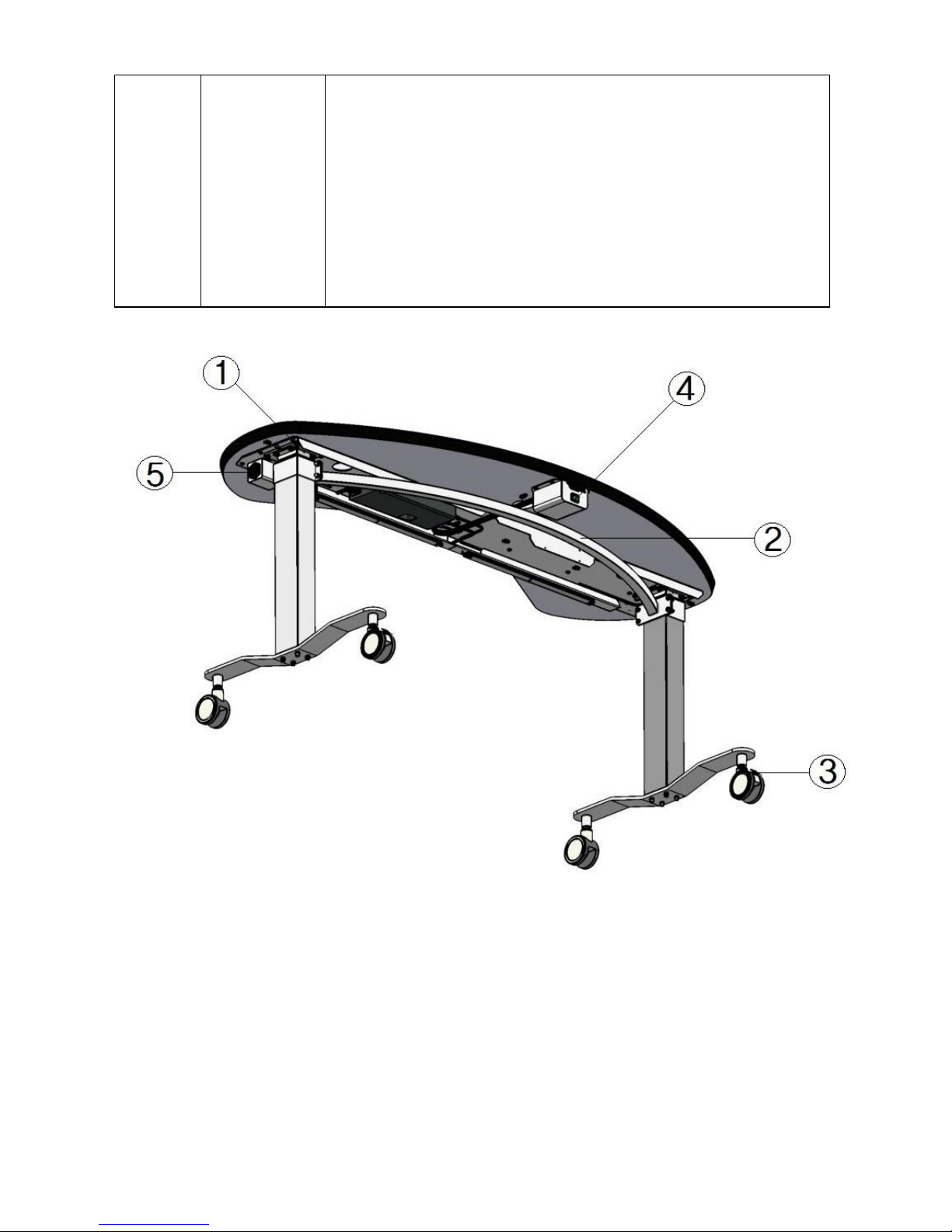
Name of each part & Function ---------------------------------------- 7
Way of Use ------------------------------------------------------------ 10
When Problem Occurs ------------------------------------------------ 12
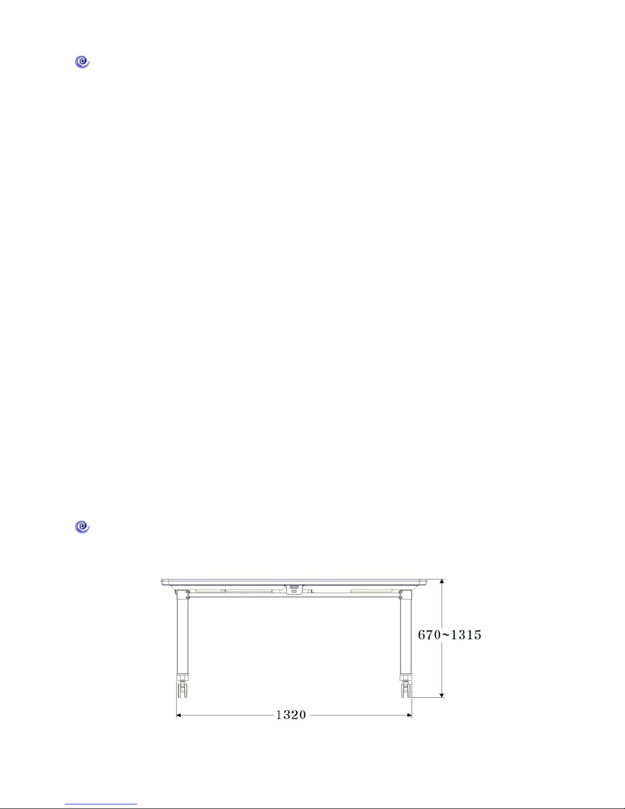
Reference Data -------------------------------------------------------- 13
Management & Inspection ------------------------------------------- 13
Replacement a fuse --------------------------------------------------- 14
Warranty Period ------------------------------------------------------- 14
Precautions of Use ---------------------------------------------------- 15
Storage & Management after use ----------------------------------- 16
Installation Guide ----------------------------------------------------- 17
Components of Box -------------------------------------------------- 26
Mentioned Items ----------------------------------------------------- 27
Map ------------------------------------------------------------------- 28
Introduction
Thanks you for purchasing this model (RT-400).
Please use RT-400 after read & understand the manual carefully
and understand it well.

-2-
Service Environment
Don’t use it under being exposed to direct sunlight.
Recommend to be used under Temperature
(Celsius: -10˚C~40˚C / Fahrenheit: 14℉~104℉),
Humidity (30% ~ 85%), Air Pressure (70~106Kpa).
Install the equipment horizontally and maintain the level for
smooth performance.
Check it out whether power code is connected
correctly all the time.
Use the voltage AC220 ~ 230V, 50/60Hz.
Power off in case of not working the device.
Indication for using Safely
This Manual is describing the important information that can be
used to guide other people who have used or to be used
properly and safely, and to prevent property damage.
Please read and understand “Safety Precautions" and the body keep
your base and then display, a sign of the following understanding.
Display and Meanings
Warning
May result in the risk of serious injury if you
ignore the display and handling of death or in
the wrong way.
Caution
This possibility is likely to be an injury people
or cause property damage if you ignore this
display and handle the wrong way.

-3-
Symbols & Meanings
Means a warning.
Displays text or picture near the sign specific information.
This means a ban.
Displays text or picture near the sign specific information.
Means the command.
Displays text or picture near the sign specific information.
Safety Precaution
Symbol
Prevent Entry
Do not disassemble the unit for repair. You may receive
an electric shock.
Please contact your dealer for repair.
Do not place the unit in a location where water or other
liquid spray. Fire or electric shock may occur.
!
Connect the single-phase AC power plug.
If plugged into a different place, you can cause a fire
and electric shock.
!
Replace, remove the power cord, fuse.
If not, you may cause an electrical shock.
Use the fuse rating.
Unplug the power cord from the device occurs ten
thousand days of smoke or other problems. Otherwise,
the risk of fire. Please contact your dealer for repair.

-4-
Symbol
Prevent Entry
When you put the device in the table, more than 5˚
Do not place unstable or tilted.
May result in injury due to the unit.
Do not place heavy objects on the table than the
specified value. May result in injury due to the unit.
Do not insert your fingers between moving equipment
operating unit. May result in injury due to the unit.
If repair is required, contact your dealer.
When assembled correctly and tighten the bolts.
May result in failure
Management
User Management
Do not manage the work of non-instructed in this manual is to
maintain safety and performance of the service is absolutely top
other equipment degradation.
The information that is listed, however, the following items can be
managed customers.
Exchange of Fuse
You can replace the Fuse.
Please refer body(main manual) how to handle
Disclaimer(Exemption from Responsibilities)
We will not be liable with respect to any caused by fire,

-5-
earthquake, acts by third parties, other accidents, user's
negligence, misuse or other damage under abnormal
operating conditions.
Caused by the use of other than those specified in the
instruction manual.
Manufacturer shall not be liable for any damages at all.
Alert and Display Position
Warning notices are to ensure safety on the unit.
Please follow the instructions of your display.
Warning
Attention
①For bolt tightening exactly lift column
assembly for fastening. Damage of
column may be caused to risk of injury.
②Do not install close to the table, the rib
height some of the work of the body
(fingers, etc.) interrupt the risk of injury
③Must use all 4 castor breakers.
All breakers attached the 4 wheels must
be locked.
The slippery equipment may cause to
injury.
④Don’t power switch off while table
up/down operation. The operation of

-6-
machine is stopped.
⑤When replacing the fuse, replace turn off
the power switch, unplug the power cord
from the wall outlet.
There is a risk of electric shock.

-7-
Name of each part & Function

-8-
Name of each part & Function
①Table : You can install 3 test equipment.
②Cable Hole : You can send down the equipment power cables.
③Control box: There is main power, table up/down switch.
④Lift Column: Assemble Column, Base and Castor.
⑤Caster: The lever is fitted with a manual stop function
⑥Power Input Box: The boxes are connected to the power cable.
Can be mounted on the left and right depending on the
ambient environment.
⑦Safety Switch: The table stops when a patient’s knee touch the
table because safety switches is working immediately.
⑧Controller: control the left and right lift column at the same time.
⑨Socket : a built-in 4-sphere is exposed outlet and connect the
power to the equipment
⑩Reinforcing Band : To prevent motion of the table and
For being fixed lift column:
⑪Reinforcing Band Bracket: The part where the reinforcing band
assembly and installation
Size of Table ( Measure : mm)
<Front View>

-9-
<Right lateral View>
<Plane View>

-10-
Way of Use
Precaution before use
①Check it out Power Voltage (220 ~ 230V)
②Power on the switch.
③Check it out whether the equipment is working or not
After connection the power supply.
How to use and operation sequence.
①Insert the power cord into the power input box
where locate the lift column next to left of the
table, and connected to utility power supply.

-11-
②On the front of the product into the green control switch to
the "I" in position, slide and then the green light is turned
on (power ON)
③The table is rising up while pushing up (▲) switch
the tables are falling down while pushing down (▼) switch.
④Slide the "O" position of the POWER switch on the control
panel. The green light will turn off (power OFF)
⑤Disconnect the power cable from the main power.

-12-
When Problem Occurs
How to operate when a problem occur.
Warning
Do not disassemble the unit for repair.
You may receive an electric shock.
Please contact your dealer if necessary for
repair.
Cautions
Do not open the control box carelessly
You may receive an electric shock
Please contact your dealer if necessary for
repair.
If a problem occurs, please check the following checklist.
Otherwise, contact your dealer.
Check List
Content
Cause
Treatment
Remark
When
table
is not
moving
up and
down
Checking
connection
power cable
The switch POWER "O"
position. Connect the power
cable to outlet.
Checking
Power switch
“On”
The switch POWER "I" position
Verify Green LED light.
Check Fuse
condition
Refer “Exchange of Fuse ”
Knee Safety
Switch
Make sure that safety
switch located at
bottom of table is
operating.

-13-
Reference
Specification & Functions
Dimension of external : 1500*670*670mm(H)
Size of Table : 1500 * 640mm
Height of Table: Lowest 670~ Highest 1,315mm
Speed of up/down of table : 38mm/sec
Weight Allowance : 150kg
Rated Voltage: AC220-230V 50/60Hz 5A
Duty Cycle : 2min on/ 18min off
Power Consumption : 240VA
Product Weight : 52kg
※The product specifications are subject to change without notice.
※This product is not available chair.
Management & Inspection
Routine Management
When not in use the product, turn off the power switch.
Do not place the product at dusty place.
Exchange of Fuse
Warning
Replace fuse after removing power code.
Otherwise, you might be receive electrical shock.
Use rating fuse only.

-14-
Unplug the power cable and make sure that verifying power
switch’s place is the "O" position.
Open the fuse folder using screwdriver or pointed tool,
the folder with the lower end of the input socket.
Replace new fuse( 5A 2EA ).
Make sure that power switch is off.
Warranty Period
The warranty period from the date of purchase of the unit for one
year are excluded from the warranty repair damage due to the
negligence of the user.

-15-
Precautions of Use.
Do not use in temperatures lower than minus 10 °
(Celsius: -10˚C / Fahrenheit: 14℉)
Make sure there are no problems with the unit and overall
patient.
Take appropriate action, such as when the patient is found in the
apparatus and over the patient, to a safe state, and stops the
operation of the equipment.
When installing the equipment, please note the following:
Install the equipment where the water does not reach.
Install in a place that will not cause adverse effects, such as
from the air, including pressure, temperature, humidity,
ventilation, sunlight, dust, salt, and sulfur.
Be careful and note that the steady-state impact
(including during transport) tilt, vibration, etc.
Do not install in a location with a storage area, etc.
chemicals or gases.
Be careful and note power consumption, power frequency,
and voltage and capacitance values allowed.
Please note the following when using the equipment.
Check the connection status of the switch, if the device
is working correctly.
Make sure all cords are connected correctly and completely.

-16-
Storage and Management after use.
Disconnect the power code after returning to the previous state,
and use power table position.
Do not force such as holding the cord when you disconnect cords
subtracting.
Be careful of followings for the storage area.
Keep out of reach in the water
Please keep in place that will not cause adverse effects, such
as air, including from the pressure, temperature, humidity,
ventilation, sunlight, dust, salt, sulfur
Note that the steady-state impact (including during
transport) inclination, vibration, etc.
Do not store in a location with a storage area such as
chemicals or gases.
Keep clean after cleaning such as accessories, cord, etc.
Clean out equipment thoroughly to avoid for next use.

-17-
Installation Guide
※All our products are tightening bolts.
※Need the following tools.
- Drivers (+)
- Hex Wrench.
- Spanner(10mm)
1. Check out all parts from the part box.
①Lift Column Base(2 units)
②Reinforce Band(Brackets are fastened)
③Top Table
④Power Cable(1 unit)
2. Place the table below for assembly.
3. Assemble switch (up & down) inside control box.
(Factory packing box inside the switch without clamping interference)

-18-
①Remove the table from the control box (Use a Phillips screwdriver)
②Assemble the control box after switch was fastened the bracket.

-19-
4. Assemble column base into the table.
①Place lift column on the bracket of table bottom.
Table of contents
Popular Indoor Furnishing manuals by other brands

Badger Basket
Badger Basket Heirloom Style Doll Cradle 1835 Assembly instructions

Songmics
Songmics VASAGLE BBC03 quick start guide

Gautier Office
Gautier Office 112-TWIN 280 quick start guide

Target
Target BK2SHLFXEB Assembly instructions

J.Burrows
J.Burrows TYPHOON PRO II Assembly instructions

BIG FURNITURE WAREHOUSE
BIG FURNITURE WAREHOUSE CRG954 quick start guide