Installation ManualAlcar®H51
5
CHAPTER IV INSTALLATION
During this section there are presented the location, the mounting and the electrical connections
necessary for the alarm system installation.
This alarm system can only be installed on cars that have the negative pole of the
battery connected to the chassis!
NOTE: Read carefully this manual before starting the installation. If you are not sure you are able
to do it by yourself, call a specialist!
4.1 SIREN MOUNTING
The siren will be mounted in the hood compartment, away from high temperature sources and
humidity. The chosen place should not be obstructed in order not to attenuate the siren sound.
Also, the place should be as inaccessible as possible to prevent the tamper.
Fasten the siren up side down by using screws.
4.2 PIN SWITCH MOUNTING AT HOOD AND TRUNK
Choose the mounting place such as the pin-switches should be able to move about 6mm. in the
closed position of the hood and trunk.
4.3 CENTRAL UNIT MOUNTING
Choose a horizontal place, hidden, preferably under dashboard. Fasten the central unit with screws
on the car chassis.
4.4 CONNECTIONS
There are 8 connectors on the central unit (A, B, C, D, E, F, G, H). The connectors correspond
respectively to the cable sets A, B, C, D, F, G, H.
The connections will be made according to the general mounting diagram (D).
4.4.1 Cable set A
Commands the central door lock system.
The timing for commanding the central door lock system can be set to 0,8s. for electric door
lock and 4s. respectively for pneumatic door lock. The selection is made through parameter
1-Timing for door lock.
Before connecting the cable A and setting parameter 1, one should determine the type of central
door lock existent on the car. A simple way is to try and lock the car doors by locking the right-front
door, by locking this door:
1) the doors are instantly closing, then the car is provided with electric door lock system
2) the doors are closing in an interval of few seconds, then the car is provided with pneumatic
door lock system
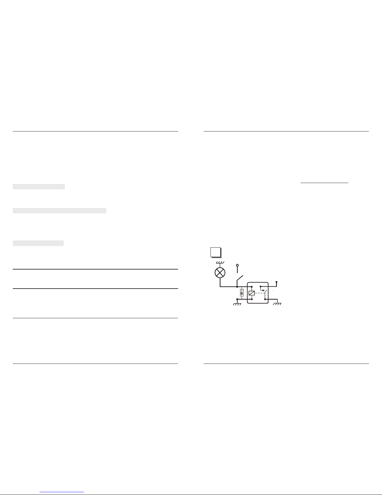
4.4.2 Cable set B
B1 (black)
System GND. Connect to (-) pole of the battery.
Note: In order to improve the noise immunity it is indicated that the power supply wires (B2-red and
B1-black) to be connected directly to the batterys poles.
20
5.14 BYPASSED FAULTED INPUTS INDICATION
If when arming the system has bypassed any input (doors, hood, sensors) within 20s after arming,
then whn disarming, after opening any door the hood or trunk, the system will indicate by the state
LED, the type of input as follows:
1 blink - shock sensor
2 blinks - ultrasonic sensor
3 blinks - contact key (attempt to start the engine)
4 blinks - door contacts
5 blinks- hood, trunk contacts
After starting the engine the faulted inputs memory will be reset and the LED will turn off.
The alarm memory is prioritary towards the faulty sensors indication. So, the LED will indicate the
faulty inputs bypassed only if there was no alarm.
5.15 ANTISCANNING/ANTIGRABBING
ALCAR®-51, is protected for scanning and grabbing.
5.16 NON-VOLATILE MEMORY FOR SYSTEM STATES
When the system is powered again (after the power was OFF), it enters the state which was
previously (armed, disarmed, service, anti-carjacking). If the system was in the arming mode when
the power was OFF, then at the power restoring the sensors state and the event memory will be
restored and the system will tripp a panic alarm.
Note: There is a certain situation namely: if parameter 11 Door contacts delay when arming is
enabled, parameter 12 Door contacts delay duration is 5s, a door is opened when arming and
the power is breaked before the fifth second from the arming, then when rearming, if the door is still
open, the system enters a door alarm .
5.17 ALARM SITUATIONS WHEN THE SYSTEM IS ARMED
1. When opening a door, the hood or the trunk alarm by siren, flashing lights and optionally
by pager, for 30s;
If a door is left opened in a burglary attempt, the system triggers the alarm (siren, flashing lights and
pager), for three times of 30s each. After the 3 x 30s alarm sequence the doors input is bypassed
and the other functions of the system are still active. This is executed even if the alarm is stopped
by remote control.
If subsequently the related door is closed, the doors input becomes active again.
2. When trying to start the engine with the key alarm by siren, flashing lights and optionally
by pager, for 30s;
3. When the car receives a weak shock optical-acoustical warning for 1s.
4. When the car receives repeated weak shocks within 5s or a strong shock alarm by
siren, flashing lights and optionally by pager, for 15s, intermittently 2s ON, 1s OFF;
5. When violating the interior of the car, if the supplementary input is set for ultrasonic
sensor alarm by siren, flashing lights and optionally by pager, for 30s;
6. When approaching the car, if the supplementary input is set for proximity sensor
programmable warning (see parameter 10).