Roger BIONIK4 Product manual

BIONIK4
Barriera automatica Brushless
Automatic barrier Brushless
Automatisierung für Schranke Brushless
Barrière automatique Brushless
Barrera automática Brushless
Barreira automática Brushless
IT - Istruzioni ed avvertenze per l'installatore
EN - Instruction and warnings for the installer
DE - Anleitungen und Hinweise für den Installateur
FR - Instructions et avertissements pour l'installateur
ES - Instrucciones y advertencias para el instalador
PT - Instruções e avisos para o instalador
IS161 Rev.03 02/09/2019

2
IT
FR
EN
ES
DE
PT
1 Avvertenze generali 3
2 Dichiarazione di conformità 3
3 Destinazione d’uso 3
4 Limiti di impiego 4
5 Descrizione del prodotto 4
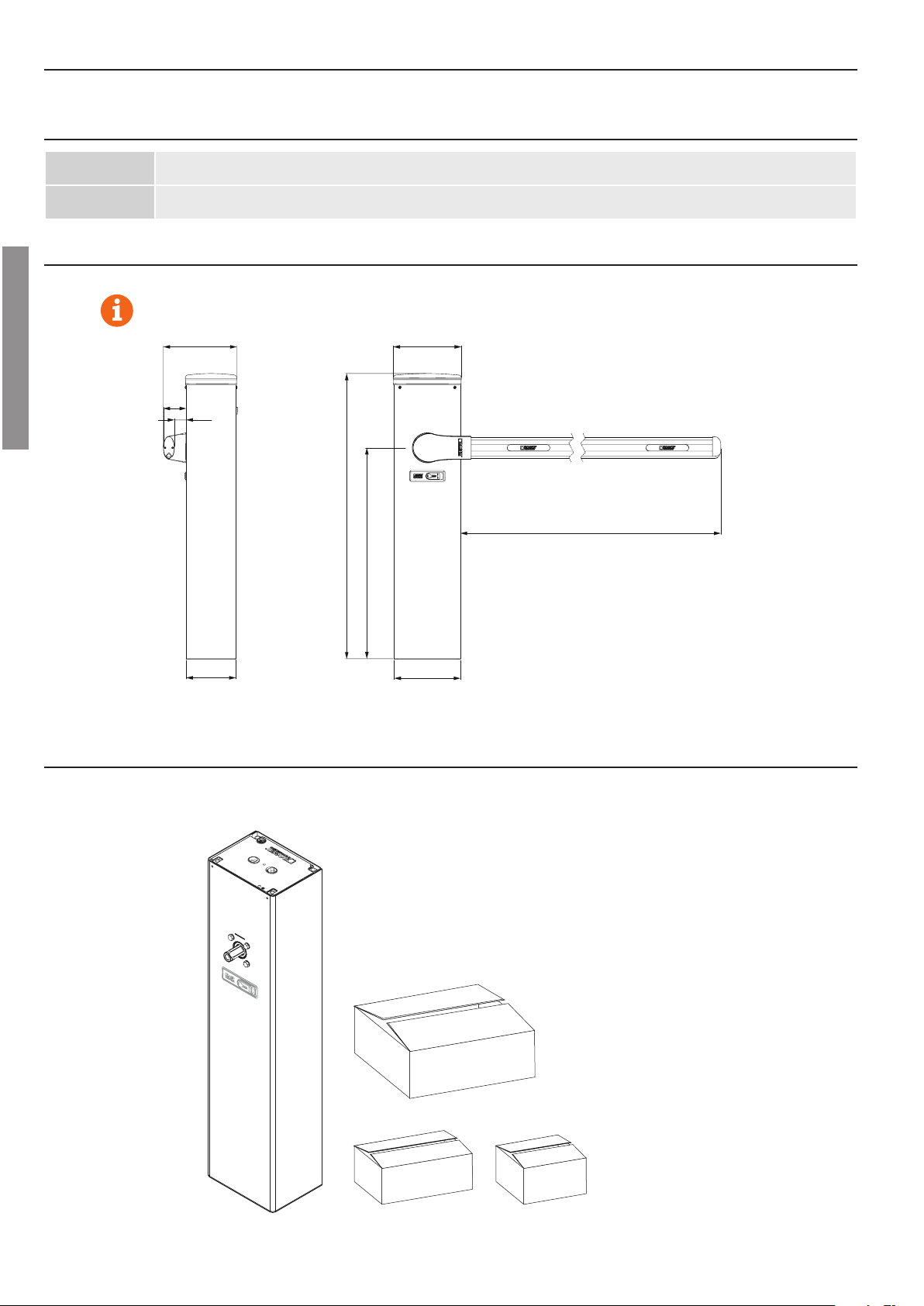
6 Dimensioni 4
7 Contenuto dell’imballo 4
8 Caratteristiche tecniche 5
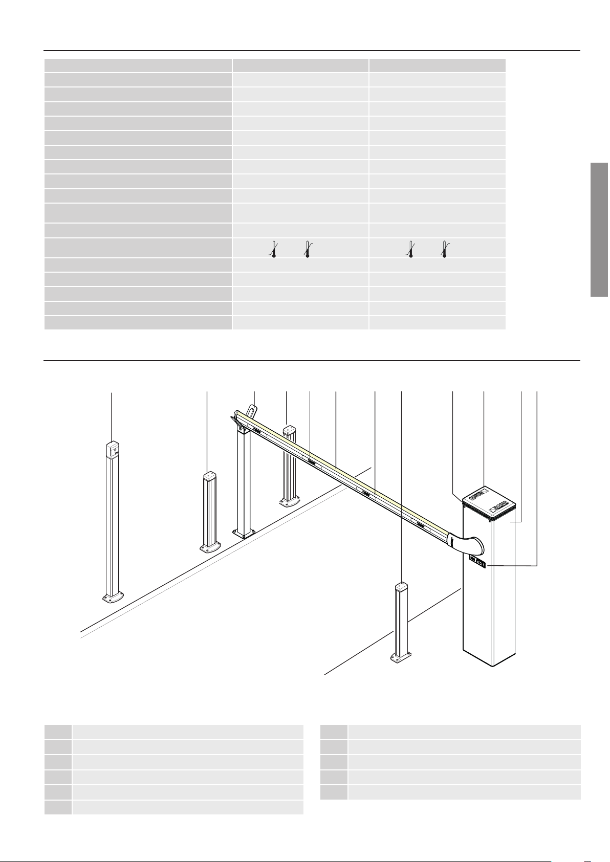
9 Installazione tipo 5
10 Riferimenti e accessori 6
11 Installazione 7
11.1 Verichepreliminari 7
11.2 Installazione piastra di base 7
11.3 Installazione barriera 7
11.4 Selezione senso di apertura 9
11.5 Installazione supporto e asta 10
12 Installazione e regolazione della molla 11
12.1 Scelta della molla 12
13 Regolazione fermo meccanico 13
14 Collegamento fotocellule 13
15 Collegamenti elettrici 14
16 Installazione kit batterie (opzionali) 14
17 Installazione lampeggiante a led bi/bled 15
18 Piano di manutenzione 16
19 Smaltimento 16
20 Informazioni aggiuntive e contatti 16
21 Operazione di sblocco / blocco 16
1 General safety precautions 17
2 Declaration of conformity 17
3 Intended use 17
4 Limitations use 18
5 Description of the product 18
6 Dimensions 18
7 Package content 18
8 Technical characteristics 19
9 Typical installation 19
10 References and accessories 20
11 Installation 21
11.1 Preliminary checks 21
11.2 Installing base plate 21
11.3 Installing the barrier 21
11.4 Selecting direction of aperture 23
11.5 Support and boom installation 24
12 Installing and adjusting the spring 25
12.1 Spring selection 26
13 Adjusting the mechanical stop 27
14 Connecting photocells 27
15 Electrical connections 28
16 Installing the battery kit (optional) 28
17 Installingthebi/bledledashinglight 29
18 Maintenance 30
19 Disposal 30
20 Additional information and contact 30
21 Release and lock procedure 30
1 Allgemeine sicherheitshinweise 31
2 Konformitätserklärung 31
3 Nutzungsbedingungen 31
4 Gebrauchsbegrenzung 32
5 Beschreibung des produkts 32
6 Abmessungen 32
7 Inhalt der verpackung 32
8 Technische daten 33
9 Typische installation 33
10 Hinweise und Zubehör 34
11 Installation 35
11.1 Vorab-prüfungen 35
11.2 Installation der grundplatte 35
11.3 Installation der schranke 35
11.4 Wahl der öffnungsrichtung 37
11.5 Installation von halterung und schlagbaum 38
12 Installation und einstellung der feder 39
12.1 Wahl der federn 40
13 Einstellung mechanischer feststeller 41
14 Anschluss der lichtschranken 41
15 Elektrische anschlüsse 42
16 Installation akkusatz (optional) 42
17 Installation led-blinkleuchte bi/bled 43
18 Wartungsplan 44
19 Entsorgung 44
20 Zusätzliche informationen und kontakte 44
21 Entriegelung und verriegelung 44
1 Consignes générales de sécurité 45
2 Déclaration de conformité 45
3 Destination d’utilisation 45
4 Limites d’emploi 46
5 Description du produit 46
6 Dimensions 46
7 Contenu de l’emballage 46
8 Caractéristiques techniques 47
9 Installation type 47
10 References et accessoires 48
11 Installation 49
11.1 Véricationspréliminaires 49
11.2 Installation de la plaque de base 49
11.3 Installation de la barrière 49
11.4 Sélection du sens d’ouverture 51
11.5 Installation support et barre 52
12 Installation et réglage du ressort 53
12.1 Choix des ressorts 54
13 Réglage de la butée mécanique 55
14 Raccordement des photocellules 55
15 Raccordements électriques 56
16 Installation du kit batteries (en option) 56
17 Installationduashclignotantàledbi/bled 57
18 Plan de maintenance 58
19 Élimination 58
20 Informations complémentaires et contacts 58
21 Opérations de déblocage et blocage 58
1 Advertencias generales 59
2 Declaración de conformidad 59
3 Uso previsto 59
4 Límites de uso 60
5 Descripción del producto 60
6 Dimensiones 60
7 Contenido del embalaje 60
8 Características técnicas 61
9 Instalación básica 61
10 Referencias y accesorios 62
11 Instalación 63
11.1 Controles preliminares 63
11.2 Instalación de la placa de base 63
11.3 Instalación de la barrera 63
11.4 Selección del sentido de apertura 65
11.5 Instalación del soporte y del asta 66
12 Instalación y ajuste del muelle 67
12.1 Cómo elegir los muelles 68
13 Ajuste del tope mecánico 69
14 Conexión de las fotocélulas 69
15 Conexiones eléctricas 70
16 Instalación del kit de baterías (opcional) 70
17 Instalación del intermitente de led bi/bled 71
18 Plan de mantenimiento 72
19 Eliminación 72
20 Información adicional y contactos 72
21 Operaciones de desbloqueo y bloqueo 72
1 Advertências gerais 73
2 Declaração de conformidade 73
3 Destino de uso 73
4 Limites de emprego 74
5 Descrição do produto 74
6 Dimensões 74
7 Conteúdo da embalagem 74
8 Características técnicas 75
9 Instalação do tipo 75
10 Referência e acessórios 76
11 Instalação 77
11.1 Vericaçõespreliminares 77
11.2 Instalação da chapa de base 77
11.3 Instalação da barreira 77
11.4 Seleção do sentido de abertura 79
11.5 Instalação de suporte e haste 80
12 Instalação e ajuste da mola 81
12.1 Escolha das molas 82
13 Ajuste do retentor mecânico 83
14 Ligação das fotocélulas 83
15 Ligações elétricas 84
16 Instalação de kits de baterias (opcionais) 84
17 Instalação do pisca de led bi/bled 85
18 Plano de manutenção 86
19 Descarte 86
20 Informações adicionais e contatos 86
21 Operações de libertação e bloqueio 86

17
EN
17
1 GENERAL SAFETY PRECAUTIONS
Failure to respect the information given in this manual may cause personal injury or damage to the
device.
This installation manual is intended for qualied personnel only.
ROGER TECHNOLOGY cannot be held responsible for any damage or injury due to improper use or any use other the intended usage indicated in this
manual.
Installation, electrical connections and adjustments must be performed by qualied personnel, in accordance with best practices and in compliance with
applicable regulations.
Read the instructions carefully before installing the product. Bad installation could be dangerous.
Before installing the product, make sure it is in perfect condition: if in doubt, do not use the equipment and contact qualied personnel only.
Do not install the product in explosive areas and atmospheres: the presence of inammable gas or fumes represents a serious safety hazard.
Before installing the motorisation device, make all the necessary structural modications to create safety clearance and to guard or isolate all the
crushing, shearing, trapping and general hazardous areas.
Make sure the existing structure is up to standard in terms of strength and stability.
ROGER TECHNOLOGY is not responsible for failure to observe Good Working Methods when building the frames to be motorised, or for any deformation
during use.
The safety devices (photocells, safety edges, emergency stops, etc.) must be installed taking into account: applicable laws and directives, Good Working
Methods, installation premises, system operating logic and the forces developed by the motorised door or gate.
The safety devices must protect against crushing, cutting, trapping and general danger areas of the motorised door or gate.
The European standards EN 12453 and EN 12445 dene the minimum safety requirements for the operation of automatic doors and gates. In particular,
these standards require the use of force limiting and safety devices (sensing ground plates, photocell barriers, operator detection function etc.) intended
to detect persons or objects in the operating area and prevent collisions in all circumstances.
Where the safety of the installation is based on an impact force limiting system, it is necessary to verify that the characteristics and performance of the
automation system are compliant with the requisites of applicable standards and legislation.
The installer is required to measure impact forces and programme the control unit with appropriate speed and torque values to ensure that the door or
gate remains within the limits dened by the standards EN 12453 and EN 12445.
ROGER TECHNOLOGY declines all responsibility if component parts not compatible with safe and correct operation are tted.
Display the signs required by law to identify hazardous areas.
Each installation must bear a visible indication of the data identifying the motorised door or gate.
An omnipolar disconnection switch with a contact opening distance of at least 3mm must be tted on the mains supply.
Make sure that upline from the mains power supply there is a residual current circuit breaker that trips at no more than 0.03A and overcurrent cutout
upstream of the electrical system in accordance with best practices and in compliance with applicable regulations.
When requested, connect the automation to an effective earthing system that complies with current safety standards.
During installation, maintenance and repair operations, cut off the power supply before opening the cover to access the electrical parts.
The electronic parts must be handled using earthed antistatic conductive arms.
Only use original spare parts for repairing or replacing products.
The installer must supply all information concerning the automatic, manual and emergency operation of the motorised door or gate, and must provide
the user with the operating instructions.
The packaging materials (plastic, polystyrene, etc.) should not be discarded in the environment or left within reach of children, as they are a potential
source of danger.
Dispose of and recycle the packing components in accordance with the standards in force.
These instruction must be kept and forwarded to all possible future user of the system.
2 DECLARATION OF CONFORMITY
I the undersigned, as acting legal representative of the manufacturer:
Roger Technology - Via Botticelli 8, 31021 Bonisiolo di Mogliano V.to (TV)
hereby DECLARE that the appliance described hereafter:
Description: Automatic barrier
Model: BIONIK4 serie
Is conformant with the legal requisites of the following directives:
• Directive 2006/42/EC (Machinery Directive) and subsequent amendments;
• Directive 2014/35/EU (Low Voltage Directive) and subsequent amendments;
• Directive 2011/65/EC (RoHS Directive) and subsequent amendments;
• Directive 89/106/CEE CPD Directive) and subsequent amendments;
and that all the standards and/or technical requirements indicated as follows have been applied:
EN 61000-6-3
EN 61000-6-2
EN 13241-1
Last two gures of year in which marking was applied |17.
Place: Mogliano V.to Date: 21-04-2017 Signature
3 INTENDED USE
The BIONIK4 automated barrier is specically conceived for installations in private or public car parks, in residential, commercial or industrial areas or in high trac zones.
This product may only be used for its expressly intended purpose. Any other usage is prohibited.
ROGER TECHNOLOGY cannot be held directly or indirectly responsible for any damage resulting from incorrect, inappropriate or unreasonable usage of this product.

18
EN
18
4 LIMITATIONS USE
BIONIK4 barriers are suitable for CONTINUOUS operation and may be used with booms up to 4 metres in length.
5 DESCRIPTION OF THE PRODUCT
BI/004 36V DC BIONIK4 BRUSHLESS barrier for booms up to 3 or 4 metre, with control unit and on-board native encoder, complete with a fastening base
with tie rods and screws and boom fastening anges.
BI/004/115 36V DC BIONIK4 BRUSHLESS barrier for booms up to 3 or 4 metre, with control unit and on-board native encoder, complete with a fastening base
with tie rods and screws and boom fastening anges. For 115 V line power supplies.
6 DIMENSIONS
7 PACKAGE CONTENT
ACCESSORIES -
BOLTS AND SCREWS
ASSEMBLED BOOM
SUPPORT
HEAD COMPLETE
WITH DIFFUSER AND
BI/BLED FLASHING
LAMP UNIT
COMPLETE BIONIK BARRIER
CABINET WITH INTEGRATED
CONTROL UNIT
All measurements are expressed in mm unless otherwise indicated.
310287
≤3000 / 4000
97 50
210 280
1203
890

19
EN
19
8 TECHNICAL CHARACTERISTICS
BI/004 BI/004/115
POWER SUPPLY 230 Vac - 50 Hz ±10% 115 Vac - 60 Hz ±10%
MOTOR POWER SUPPLY 36 Vdc 36 Vdc
POWER CONSUMPTION from 0 to 15 A from 0 to 15 A
POWER MOTOR 220 W 220 W
TORQUE from 0 to 200 Nm from 0 to 200 Nm
OPEN / CLOSE TIME 90 ° (booms up to 3 m) from 2 to 6 sec from 2 to 6 sec
OPEN / CLOSE TIME 90 ° (booms up to 4 m) from 3 to 6 sec from 3 to 6 sec
CONTROL SYSTEM ABSOLUTE ENCODER DIGITAL ABSOLUTE ENCODER DIGITAL
USE FREQUENCY CONTINUOUS CONTINUOUS
OPERATING CYCLES PER DAY (OPENING/CLOSING
- 24 HOURS NO STOP) 5000 5000
GRADE OF PROTECTION IP54 IP54
OPERATING TEMPERATURE -20°C +55°C -20°C +55°C
CONTROL UNIT (INTEGRATED) 36 Vdc CTRL (since version FW r3.25) CTRL (since version FW r3.25)
ACCESSORIES POWER SUPPLY 24 Vdc 24 Vdc
BOOM up to 4 metres up to 4 metres
EMERGENCY BATTERY OPTIONAL OPTIONAL
RELEASE SYSTEM KEY WITH A STANDARD CYLINDER KEY WITH A STANDARD CYLINDER
9 TYPICAL INSTALLATION
1Automatic Barrier BIONIK4 serie
2Integrated control unit
3Flashing lights
4External Photocell
5Boom with shockproof rubber
6Strip led
7Reective sticker
8Internal Photocell
9Fixed end rest for boom complete with a shock-resistant rubber mechanical stop
10 Release system
11 Key or keypad release switch
11 4986
75432110

20
EN
20
Code Description
1BI/004 Barrier unit cabinet, in carbon steel with anti-corrosion
treatment and painted.
BI/004/115
2Key release with a standard lock
RL670 Key release with DIN cylinder (OPTIONAL)
3Boom support arm rear cover
4
BA/68/3 Elliptical boom up to 3 m, in white painted aluminium
with slot cover proles and shock-resistant rubber.
BA/68/4 Elliptical boom up to 4 m, in white painted aluminium
with slot cover proles and shock-resistant rubber.
5Boom support arm in die-cast aluminium.
6Boom support arm front cover.
7Head in die-cast aluminium with anti-corrosion treat-
ment and painted, complete with diffuser in transpa-
rent polycarbonate and BI/BLED led lights.
8 CTRL Controller unit
9Gate open/close mechanical stop
10 Steel spring fastening linkage lever
11 Gear motor complete with brushless motor and abso-
lute encoder
12 Corrosion-proof, painted steel inspection hatch.
13 KT240 Galvanised base plate for barrier fastening.
14 BI/ALED4C 4 m LED strip.
15 SP/48/01 Green Ø48 spring (for booms and accessories, see
chap. 12).
16 SP/61/01 Blue Ø61 spring (for booms and accessories, see
chap. 12).
10 REFERENCES AND ACCESSORIES
Code Description
17 SP/72/01 Red Ø72 spring (for booms and accessories, see chap.
12)
18 KT231 Fixed end rest fastening plate.
19 BAFS/01 Fixed end rest, non-adjustable, with rubber buffer.
20 BAFS/03 Fixed end rest with rubber, non-adjustable, with holes
for a latch chain and rubber buffer.
21 BAFS/02 Fixed end rest with rubber, adjustable, telescopic with
rubber buffer.
22 BAFS/04 Fixed end rest with rubber, adjustable, telescopic with
holes for a latch chain and rubber buffer.
23 BAFS/05 Fixed end rest with rubber, adjustable, telescopic with
rubber buffer and integrated magnet.
24 BAMS/01 Hinged end rest for booms.
25 BAMS/01/EXT Extension for hinged end rest
26 BARK/02 Drop skirt in painted aluminium. L = 2 m.
27 SND/BA/68/DW Joint with 90° pivot point with lower tie-rod
28 SND/BA/68/UP Joint with 90° pivot point with upper tie-rod
29 BI/BAT/KIT Emergency battery kit complete with battery charger
and wiring (optional).
30 BI/BCHP Battery charge board complete with wiring (optional)
31 KT239 DIN bar
32 R99/BASB20 Package of 20 refractive adhesive strips for the boom.
R99/BASB40 Package of 40 refractive adhesive strips for the boom.
33 RS/GR1/100 Lithium grease (EP LITIO).
9
7
8
9
10
1
4
3
2
5
6
14
4
11
12
13
1615 17 19 20 21 2322
25
26
29
30 31 32
33
27 28
18
24

21
EN
21
2
11 INSTALLATION
11.1 Preliminary checks
• Check that the material received is in good condition and suitable for the
application.
• Check that the operating limits of the product are not exceeded.
• Check that the site chosen for installation meets the overall space requirements of
the product and that there are no obstacles hindering open or close manoeuvres.
• Check the concrete base for the barrier installation. The base must be cast in
accordance with proper working practices, perfectly level and clean.
11.2 Installing base plate
The illustrations herein are indicative only. The space necessary for fastening
the automation system and the accessories may vary depending on the overall
dimensions of the installation. The installer is responsible for determining the most
suitable solution.
• Excavate a foundation pit measuring 1m x 1m x 0.4 m and ll with concrete
reinforced with steel mesh.
• Fasten the 4 anchor ties to the plate (g. 1). N.B.: the bottom nut must be
tightened to the end of the thread on the screw so that the length Z is at least
40 mm.
• Sink the base plate with the anchors in the centre of the foundation pit, so that
the surface is ush with the concrete and perfectly level. The corrugated cable
conduits must protrude by a few centimetres from the centre of the plate.
PAY ATTENTION to the installation direction of the plate. See the detailed
viewing.2.Theinspectionsidemustbeaccessiblefrominsidethehome/
shop / business.
• Installation on existing surfaces. Place the base plate on the surface and trace
the positions of the fastener points. Drill the surface and t 4 expansion anchor
bolts (purchased separately).
11.3 Installing the barrier
N.B.: the barrier is congured by default for installation on the right hand side
(viewed from the inspection hatch).
• Undo and remove the washers and nuts from the anchors on the base plate (g.
3).
• Open the inspection hatch, turning the key clockwise 90° (g. 4) and remove it.
• Place the cabinet on the plate. The anchors on the base plate must t through
the four slots.
• Fit the washers and nuts removed previously. Move the cabinet as necessary in
the slots to adjust the position of the barrier correctly.
• Tighten the nuts securely (g. 6).
280
210
216
125
1
280
210
Z=>40 mm
KT
240
97
210
280
59 100 51
116125
4xØ12,5
216
73
86
54 40
Lato sportello di ispezione
Inspection hatch side
53
118
≥160

22
EN
22
4
6
5
90°
3

23
EN
23
11.4 Selecting direction of aperture
BIONIK4barriersareconguredbydefaultforinstallationontherighthandside(seenfromthe
inspection hatch side).
Whenever corrective actions are carried out, pay the utmost attention when releasing, locking or
moving the internal mechanical parts. These operations could be hazardous for the installer.
For left hand installations:
• Unlock the barrier (see chapter 21).
• Turn the linkage lever as shown in gure.
• Move the mechanical stop.
• Lock the barrier (see chapter 21).
OPENING
ON THE LEFT
OPENING
ON THE RIGHT
7
BARRIER INSTALLED ON THE RIGHT (SEEN FROM THE INSPECTION HATCH SIDE)
AND THE BOOM OPENING/CLOSURE GATE ON THE LEFT
BARRIER INSTALLED ON THE LEFT (SEEN FROM THE INSPECTION HATCH SIDE)
AND THE BOOM OPENING/CLOSURE GATE ON THE RIGHT

24
EN
24
8
11.5 Support and boom installation
1. Unlock the barrier (see chapter 21).
2. Based on the opening direction of the barrier (g. 7), turn the linkage lever until reaching the stop on the mechanical limit switch (g. 7), in the position in which it is
possible to install the boom horizontally.
3. Lock the barrier.
4. Open the boom support cover [A] by unscrewing the self-tapping screws TCC 4.2x19 [B] .
5. Loosen the screws [E1] and insert the boom support [C] on the drive shaft [D] making sure that there is a maximum distance of 1 mm between the support and the
barrier cabinet, as shown in the detailed view.
6. Fasten the support with the TCEI M8x35 screws [E1], [E2] and [E3] tightening them securely.
7. Fasten the rear cover with the provided self-tapping screws [F] TCC 4.2x19.
8. Unscrew the screws [G] TCC 4.2x13 and remove the cap [H].
9. Unscrew the screws [I] TCC 2.9x19. Remove the support [L], shock-resistant rubber [M] and the prole [N] at least 200 mm.
10. Insert the boom [O] in the support [C] and fasten it with the provided screws TCEI M8x20 [P] (complete with washers).
11. Reposition the prole [N], the shock-resistant rubber [M] and the plastic support [L] and fasten them with the screws [I] TCC 2.9x19.
12. Fasten the cap [H] with the screws [G] TCC 4.2x13.
13. Fasten the plastic support cover [A] with the self-tapping screws TCC 4.2x19 [B].
A
C
E2
E1
B
G
H
M
200
L
D
C
F
I
P
P
E3
E3
E3
N
O
1 mm
C
C

25
EN
25
12 INSTALLING AND ADJUSTING THE SPRING
• Select the desired opening direction as indicated in paragraph 11.4.
• Unlock the barrier (see chapter 21) and move the boom into the completely open vertical position.
• Select the most suitable spring (see tables in paragraph 12.1).
• The springs are colour coded for identication. The coloured part of the spring must always be at the top:
– green - Ø48 springs (SP/48/01);
– blue - Ø61 springs (SP/61/01);
– red - Ø72 springs (SP/72/01).
• Unscrew the upper screw TE M14x60 of the spring (viewed from the top coloured side).
• Unscrew the screw TE M14x45 from the linkage lever and fasten the spring with the same screw (g. 9):
• - For barriers with left-side opening, use the SX1 or SX2 holes.
• - For barriers with right-side opening, use the DX2 or DX3 holes.
• Fasten the springs to the xed structure (g. 9), on the steel cross bar of the barrier, using the screws TE M14x60 included in the package.
• Lubricate the pivot points with lithium based grease (EP LITIO) (g. 10). Available upon request, article RS/GR1/100: 100 g can of lithium grease.
• To adjust the spring tension, loosen the nuts [A] as indicated in g. 10-11. Then turn the spring [B] clockwise to reduce the tension or anticlockwise to increase tension
(g. 11).
• Lift the boom manually to an angle of 45° and let go. If the boom rises, reduce the spring tension. If the boom drops, increase the spring tension.
• Once the spring tension is correct, tighten the nuts securely [A].
9
10 11
TE M14x60
Sinistra (SX)
Lef
t (LT)
Destra (DX)
Right (RT)
TE M14x45
1
2
123
TE M14x60
G
r
a
s
s
o
G
r
e
a
s
e
BB
A
A
-+
45° >45°
<45°

26
EN
26
12.1 Spring selection
The adjustable xed end rest with
integrated magnet BAFS/05 must be
used.
The adjustable xed end rest with
integrated magnet BAFS/05 must be
used.
The adjustable xed end rest with
integrated magnet BAFS/05 must be
used.
Conguration only possible if the drop
skirt is installed as close as possible to
the cabinet.
Thexedendrestmustbeused.
The booms are understood as complete with shock-resistant rubber and LED strips.
BA/68/3
(with boom from 2,2 to 2,80 m)
BA/68/3
(boom up to 3 m) BA/68/4
(boom up to 4 m)
SP/48/01
Verde/Green
NOT AVAILABLE NOT AVAILABLE
SP/61/01
Blu/Blue
NOT AVAILABLE
NOT AVAILABLE NOT AVAILABLE
2 m 2 m
NOT AVAILABLE
NOT AVAILABLE
NOT AVAILABLE NOT AVAILABLE
SP/72/01
Rosso/Red
NOT AVAILABLE NOT AVAILABLE
2 m
NOT AVAILABLE
2 m 2 m
NOT AVAILABLE NOT AVAILABLE
2 m1m
NOT AVAILABLE
2 m 2 m
NOT AVAILABLE NOT AVAILABLE
2 m1m
NOT AVAILABLE
NOT AVAILABLE

27
EN
27
14 CONNECTING PHOTOCELLS
F4ES type photocells may be installed on both sides of the barrier at two different heights: (50 cm or 100 cm).
1. Disconnect the mains power (if applicable).
2. Switch the control unit switch to the OFF position (g. 15).
3. Open the photocells, rest the base on the cabinet and use it as a drilling template.
4. Drill the barrier cabinet as shown in gure 13 and fasten the base of the photocells.
5. Route the connector cables upwards, taking care not to interfere with the movements of the automation system and through the cable conduit indicated in gure 14.
6. Connect the photocells to the terminals COM-FT1/FT2 as indicated in the control unit installation manual.
7. Refer to the control unit manual for the photocell settings.
8. Set the switch to the ON position.
9. Reconnect to mains power.
13 14
13 ADJUSTING THE MECHANICAL STOP
The gure shows the mechanical stop on a barrier installed on the LEFT hand side.
For barriers installed on the RIGHT, perform the mirror images of the procedures
illustrated.
• Unlock the barrier (see chapter 21).
• Set the completely open [AP] and completely closed [CH] positions by adjusting
the relative mechanical stops.
• Lock the barrier (see chapter 21).
12
AP
CH
RX
RX
TX
TX
4xØ3,25
990
490
Ø15

28
EN
28
15 ELECTRICAL CONNECTIONS
All electrical connections must be made with the unit disconnected
from mains power and, if applicable, battery power.
See controller manual for instructions on making connections and
programming.
Before connecting to electrical power, ensure that the mains power
specications on the identication plate match the mains power
supply used.
A switch or an omnipolar cut-off switch with a contact opening of at
least 3 mm must be installed on the mains power line.
Ensure that an adequate residual current circuit breaker and a
suitable overcurrent cut-out are installed ahead of the electrical
installation.
Use a 3x2.5 mm2 double insulated cable for the mains power line.
Feed the cable on the left hand side of the barrier through the rubber
cable grommet on the left hand side of the controller casing and
connect it to the terminals L (brown), N (blue) and (yellow/
green) inside the automation unit.
Fasten the power cable with the cable grips included.
At least 50 mm of the connector cable conduit must protrude from
the holes in the base plate and into the automation unit.
16 INSTALLING THE BATTERY KIT (OPTIONAL)
1. Disconnect the mains power.
2. Unscrew the screws and remove the head [A] (if applicable).
3. Lift the cable grommet [B] and disconnect the connector [C].
4. Open the transparent control unit cover [D].
5. Switch the control unit switch to the OFF position [E].
6. Lift the control unit and insert the batteries in their housing [F].
7. Connect the red, black and blue wires to the batteries (see detailed view)
8. Connect the batteries to the +BATTERY terminal (red wire) and -BATTERY terminal (black wire).
9. Insert the battery charge board BI/BCHP in the plug-in connector [G].
10. Reposition the control unit.
11. Switch the control unit switch to the ON position [E].
12. Reposition the transparent control unit cover [D].
13. Reconnect the connector [C] and close the cable grommet [B].
14. Close the head [A] and tighten the front screws.
15. Reconnect the mains power.
15
16
A
E
GG
F
B
C
D
OFF
BLACK
RED
BATTERY (+)
BATTERY C
SEC2
BATTERY (-)
12345
ROSSO/RED (+)
NERO/BLACK (-)
BLU/BLUE
L
N

29
EN
29
17 INSTALLING THE BI/BLED LED FLASHING LIGHT
The BI/BLED ashing lamp unit is factory supplied already pre-installed in the head [A], packaged separately inside the BIONIK4 package.
1. Insert the connector [B] in the LIGHT terminal of the control unit.
2. Refer to the control unit manual for the ashing lamp unit settings.
3. Fasten the cable grommet [C], making sure it is positioned correctly.
4. Position the head [A] on the barrier.
5. Tighten the fastening screws.
In case of replacement:
1. Disconnect the mains and battery power supplies (if applicable).
2. Unscrew the screws that fasten the head [A] to the barrier.
3. Lift the cable grommet [C].
4. Disconnect the connector [B].
5. Remove and overturn the head [A].
6. Remove the BI/BLED ashing lamp unit [D] from the diffuser.
7. Insert the new LED circuit in the diffuser, paying attention to the installation direction (g. 18).
8. Insert the connector [B] in the LIGHT terminal of the control unit.
9. Refer to the control unit manual for the ashing lamp unit settings.
10. Fasten the cable grommet [C], making sure it is positioned correctly.
11. Reposition the head [A] on the barrier.
12. Tighten the fastening screws.
13. Reconnect the mains and battery power supplies (if applicable).
17
18
B
C
A
B
A
LED LIGHT
A
D
D

30
EN
30
18 MAINTENANCE
N.B.: Only use original spare parts when repairing or replacing products.
The installer must provide the user with complete instruction for using the
motorised door or gate in automatic, manual and emergency modes, and must
hand the operating instructions to the user of the installation upon completion.
The installer must compile the maintenance log book, in which all scheduled and
unscheduled maintenance operations performed must be indicated.
• The installation must be subject to regular maintenance. We recommend
servicing at least once every 6 months.
• Disconnect from mains electricity and from battery power (if applicable) to avoid
the risk of accident or injury.
• Check the tightness of all the fastener screws and nuts.
• Clean the photocell lenses with a cloth moistened slightly with water. Do not
use solvents or other chemical products, as these may damage the electronic
components.
• Clean and lubricate the pivot points with lithium based grease (EP LITIO).
• Check the electrical connections.
• Check that the manual lock release system works.
• Check that the boom is balanced correctly as indicated in chapter 12.
• Check that there are now plants within the radius of action of the boom which
could interfere with the photocells or with the movements of the boom itself.
Reconnect to mains power.
• Check that the safety devices and all the control functions work correctly.
• Check that the obstacle detection function works correctly.
• Check that there is no risk of the boom accidentally lifting persons or objects.
• Check that the force limiting function prevent potentially dangerous situations in
compliance with the standard EN 12445.
19 DISPOSAL
This product may only be uninstalled by qualied technical personnel,
following suitable procedures for removing the product correctly and
safely.
This product consists of numerous different materials.
Some of these materials may be recycled, while others must be
disposed of correctly at the specic recycling or waste management
facilities indicated by local legislation applicable for this category of product.
Do not dispose of this product as domestic refuse.
Observe local legislation for differentiated refuse collection, or hand the product
over to the vendor when purchasing an equivalent new product.
Local legislation may envisage severe nes for the incorrect disposal of this product.
Warning! some parts of this product may contain substances that are harmful to
the environment or dangerous and which may cause damage to the environment or
health risks if disposed of incorrectly.
20 ADDITIONAL INFORMATION AND
CONTACT
ROGER TECHNOLOGY is the exclusive proprietor holder of all rights regarding this
publication.
ROGER TECHNOLOGY reserves the right to implement any modications without
prior notication. Copying, scanning or any alterations to this document are
prohibited without express prior authorised from by ROGER TECHNOLOGY.
ROGER TECHNOLOGY CUSTOMER SERVICE:
business hours: Monday to Friday
08:00 to 12:00 - 13:30 to 17:30
Telephone no: +39 041 5937023
E-mail: support@rogertechnology.it
Skype: service_rogertechnology
FIG. 1
Unlock the barrier in the event of a power outage or before performing scheduled maintenance or repairs. The unlock procedure must be performed with the boom in the
closed position.
Ensure that there are no persons, objects or animals within the operating radius of the barrier when unlocking.
RELEASE AND MANUAL OPERATION
Open the lock cover as indicated in step 1.
Insert the key included into the lock and turn clockwise by 90°, as indicated in step 2.
Open the release cover completely (3).
Move the boom manually.
RESTORING AUTOMATIC OPERATION
To relock the barrier, close the release cover by turning the key 90° clockwise, paying attention to your ngers.
With the door closed, turn the key 90° anticlockwise.
Remove the key and close the lock cover.
FIG. 2
90°
1
23
21 RELEASE AND LOCK PROCEDURE
Whenever corrective actions are carried out, pay the utmost attention when releasing, locking or moving the internal mechanical parts. These operations could
be hazardous for the installer.
Table of contents
Other Roger Automatic Barrier manuals
Popular Automatic Barrier manuals by other brands

Bauer
Bauer XPASS B 275/800C L Instructions for installation, use and maintenance

Erreka
Erreka ULTRA Series Quick installation and programming guide

quiko
quiko QK-CT273800LK4 Instructions for installation, use and maintenance

eSSL
eSSL BG100 user manual

Tiso
Tiso RB343-21 Operation manual

SEA
SEA VERG 24V manual