nologo ACTIVE-A Series User guide

ACTIVE-A
Barriera Antifurto per varchi d’accesso, su alluminio nero o bianco, copertura in policarbonato.
Contatto TAMPER, Anti-intrusione.
Istruzioni e avvertenze per l’installatore
ACTIVE-A_020712_VXX04_IT_GB www.ebtechnology.it www.nologo.info
A502/A1004/A1506/A2008/A505/A1010/A1515/A2020
RoHS
C O M P L I A N T
E’ composta da un ricevitore ed un trasmettitore ed è
The barrier is composed of one receiver and one
transmitter and it is in the following dimensions avai-
Due to the special lens on the transmitter it is pos-
The output is available with isolated contact relay
relay.
Manual and directions for the installer
IT
GB
IT
GB

Premessa
-
-
Safety precautions
Environmental protection measures
Larghezza / Width
SpeSSore / thickneSS
aLim. / poWer SuppLy
portata / range up
Caratteristiche / Technical Description
-
very carefully when you purchase the instrument and consult it
whenever you have doubts regarding use and before performing
any maintenance operations.
personally will void the warranty. Nologo declines any responsi-
bility for damages due to inappropriate use of the product and
due to any use other than the use the product was designed for.
Information regarding the environment for customers within the
be disposed of separately from undifferentiated urban wastes.
The symbol indicates that the product must not be disposed of
with the normal household wastes. The owner is responsible
for disposing of this product and other electrical and electronic
by the government or local public agencies. Correct disposal and
recycling help preventany potentially negative impact on the en
vironment and human health. To receive more detailed informa-
tion regarding disposal of your unit, we recommend that you con-
tact the competent public agencies, the waste collection service
or the shop where you purchased the product.
•
•
Modelli disponibili e relativi assorbimenti / Models available and absorption
Modelli / Version
ACTIVE-A
N° raggi /
N°of rays
Ass. Bassa Potenza /
Abs. Low Power (mA)
TX RX TX+RX
Ass. Media Potenza /
Abs. Medium Power (mA)
TX RX TX+RX
Ass. Alta Potenza /
Abs. High Power (mA)
TX RX TX+RX
Precauzioni di sicurezza
-
Misure di tutela dell’ambiente
-
-
le altre apparecchiature elettriche ed elettroniche mediante le
pubblici locali. Il corretto smaltimento ed il riciclaggio aiuteranno a
dettagliate circa lo smaltimento delle vecchie apparecchiature
Foreword
Sincronizzazione /
Synchronization
uScite / output
tempo di riSpoSta /
reSponSe time

1 Installazione
A
BB
Le LENTI NERE
esempio negli antifurti casa.
Le LENTI TRASPARENTI-
metri. E’ possibile che altri moduli barriera installati nelle vici-
-
mento anomalo.
POTENZA
-
Utilizzare la potenza alta solo
in ambienti esterni o quando
si deve coprire una notevole
distanza.
• MORSETTI 1-2: Alimentazione
corrente alternata.
• MORSETTI 3-4: Tamper
-
• MORSETTO 5: Bus
ON KE
12
ON KE
12
ON KE
12
4
35
2
- Alim.
+ Alim.
1
Tamper
Tamper
Bus
Il foro preintagliato Asul retro del cappuccio permette l’inserimento dei cavi nella barriera.
B
di legge.
-
LENTE NERA
LENTE
ITALIANO
ON
2
143
non usato
ON KE
12
DIP impostazione
potenza

IMPOSTAZIONE RITARDO
raggi.
RX
NO!!! OK!!!
• MORSETTI 1-2: Alimentazione
-
ternata.
• MORSETTI 3-4: Tamper
• MORSETTI 5-6: Allarme
• MORSETTI 7: Bus
IMPOSTAZIONE ALIMENTAZIONE
IMPOSTAZIONE TENSIONE
ALIMENTAZIONE
jumper che serve per impostare
DIP 1 OFF
DIP 1 ON-
DIP 2 ON
6
57
4
- Alim.
+ Alim.
3
Tamper
Bus
1 2
Allarme
RX
E’ molto importante che il ricevitore e il trasmettitore della barrie-
ra siano ben allineati per ottenere il miglior risultato in termini di
Altra cosa importante è la luce diretta del sole all’interno del ri-
cevitore. Anche se i sensori sono protetti in modo da esserne
totalmente immuni, una forte sorgente di luce diretta nel foro del-
la copertura dei sensori potrebbe provocarne l’accecamento e
Si consiglia quindi di posizionare il ricevitore nella direzione, dove è meno probabile
che questo evento accada. Anche nell’installazione di più barriere, evitare che un ricevitore
veda direttamente 2 o più trasmettitori.
Tamper
Allarme
ON
2
143
ON
2
143
ON
2
143
ON
2
143

Eed F
Amontato
con ben inseriti i cappucci Be C. Il foro Gdei cavi deve essere
F.
tasselli D.
Bal supporto nel foro E
H.
4. ATTENZIONE!! Se la barriera viene utilizzata in ambiente
esterno, Deve essere eseguito un foro si scolo nella parte
inferiore del cappuccio C.
-
puccio C, eseguire i collegamenti alla morsettiera della barriera
A.
Inserire il cappuccio C nella barriera A
del cappucio la parte di cavi in eccesso.
C
H.
2 FISSAGGIO delle barriere
E ed
F
barriera Amontato con ben inseriti i cappucci Be Csui
supporti Ied L. Il foro Gdei cavi deve essere sopra i fori
F.
-
serirci i tasselli D.
-
tanti H.
4. ATTENZIONE!! Se la barriera viene utilizzata in am-
biente esterno, Deve essere eseguito un foro si sco-
lo nella parte inferiore del cappuccio C.
Be Cnella barriera Aeseguendo pri-
ma i collegamenti alla morsettiera del modulo. Quando
-
lare dal foro il cavo in eccesso.
A, Be C nel sup-
porto I.
Inserire il supporto Lnel foro del cappucio inferiore Ce
H.
-
EDBH
A
HC
D
G
I
HDE
B
C
H
L
D
G
A

3 FUNZIONAMENTO della BARRIERA
ON KE
12
-
controllare che l’uscita allarme commuti di stato dopo il ritardo impostato con
lente e potenza
DISTANZA AMBIENTE LENTE POTENZA
INTERNO NERA MEDIA
INTERNO NERA ALTA
INTERNO ALTA
NERA ALTA
MEDIA
ALTA
-
LED DI SEGNALAZIONE
INDICA LA QUALITA’ DEL
Si consiglia possibilmente di controllare la qualità del segnale nel momento di massima luminosità e anche nel
momento di minima luminosità soprattutto se la barriera è esposta direttamente alla luce del sole.
pause
pause
pause
pause
pause...
pause...
pause...
pause...
LED Qualità Segnale
Per circa 2 minuti dall’ultimo allarme il led emette un numero da 1 a 4 di lampeggi.
ATTENZIONE!
La versione Total White comporta una
diminuzione della potenza pari al 50 %

4 DIMENSIONI EFFETTIVE delle BARRIERE
-
Modelli serie
ACTIVE-A
Dimensioni
effettive con
cappucci [cm]
Modelli serie
ACTIVE-A
Dimensioni
Effettive con
tappi [cm]
Vers. CAPPUCCI Vers. TAPPI
6 Risoluzione dei problemi
PROBLEMA:
SOLUZIONE:
sorgente di luce come il sole od un faretto oppure un altro dispositivo infrarosso.
PROBLEMA:
SOLUZIONE: -
PROBLEMA: La barriera è montata in ambiente interno o esterno insieme ad altre barriere e va in allarme soprattutto
SOLUZIONE: -
5 ACCESSORI per BARRIERE
Colori disponibili: Nero, Bianco.
Tappi chiusura in gomma
Colori disponibili: Nero, Bianco.

1 Installation
A
BB
The transmitter is the module where the lenses are installed
• Black lenses are used in case where other module applica-
• Trasparent lenses are used outside where the range up is
available because they can interfere.
SET UP OF THE POWER
To select the power, set the dip
as shown.
We suggest to use the high
power outside or when you
need a big range up.
The terminal boards for the connections are in the end of the module:
• Pole 1 is the positive and Pole 2 is the negative,
• Poles 3 and 4 are for the antitheft contact of tamper contact.
This contact is closed when the polycarbonated part is installed and it is open
when the part has been moved.
• Pole 5
ON KE
12
ON KE
12
ON KE
12
LOW POWER
MEDIUM POWER
HIGH POWER
4
35
2
- Power Supply
+ Power Supply
1
Tamper
Tamper
Bus
The pre-caving hole Ais for the cables.
The hole Bhas to be drilled from inside just to insert the cables in the barrier or for drainage
in case of condensation.
ENGLISH
ON
2
143
not used
ON KE
12
DIP power setting

time and to avoid the alarm contact when a single ray has been obscured.
RX
NO!!! OK!!!
In the end of the receiver there is the terminal board for the connection.
• Pole 1 and 2 are for the positive and negative power supply. The receiver
In the pole 3 and 4 is the TAMPER contact.
In poles 5 and 6-
• Pole no. 7
In the terminal board side is
the power supply. It is open
is selected while it is closed
is selected.
-
tion time is:
rays are obscured and the planning intervention time depends
6
57
4
- Power supply
+ Power supply
3
Tamper
Bus
1 2
Allarm
RX
It is important that the receiver and transmitter are aligned for the
best reception of the signal. When the alignment is not good, the
direct sun-light.
Even If the sensors of the receiver are totally protected from light,
-
ration and the alarm of the barrier.
We suggest to install the receiver to avoid this
phenomenon. In case of installation of more couples
of barriers, check the alignment of the receiver .
Tamper
Allarm
RECEIVER
ON
2
143
ON
2
143
ON
2
143
ON
2
143

Eand F
right position of the module A with the covers Band C. The hole
GF
D
Bto the hole Ewith self-tapping screw H
4. WARNING!!!
hole in the lower part of the cover C.
C-
tions of the barrier A.
Plug the cover Cin the barrier A
Cwith the a self-tapping screw H.
2 FIXING OF BARRIER
Eand Fand
Band C with bearing I and L. The hole Gshould be
F.
D
Bto the hole Ewith self-tapping screw H
4. WARNING!!!
drainage hole in the lower part of the cover C.
plug the covers Band Cin the barrier A. Plug the co-
Plug the upper part of A, B, Cin the part I.
Plug the part Lin the lower part of the cover C
with self-tapping screw H.
small self-tapping screw.
EDBH
A
HC
D
G
I
HDE
B
C
H
L
D
G
A

4 Operation of the barrier
that the output change the status after set up of the planning intervention time
The l.e.d. in the middle of the receiver indicate the status of the alarm when it
In the table you can see the type of lens and the power of the transmitter according to the distance with the receiver.
We remind you that for inside we mean all places where there is no direct sun-light
DISTANCE LENSES POWER
BLACK MEDIUM
BLACK HIGH
HIGH
BLACK HIGH
MEDIUM
HIGH
We suggest to use the high power if the absorption is low and the distance between receiver and transmitter
We suggest to check the quality of the signal at the maximum and minimum brightness
above all if the barrier is positionated to the direct sun.
pause
pause
pause
pause
pause...
pause...
pause...
pause...
LED Signal Quality
After 2 minutes of the last alarm, the l.e.d. ashes from 1 to 4 times.
WARNING!!!
The white version of the barrier can reduce
the range up to 50%.
ON KE
12
SIGNALING LIGHT
FIXING HOLE
RECEIVER

5 REAL DIMENSION of the barriers
Models of
ACTIVE-A
Real dimensions
with covers [cm]
Models of
ACTIVE-A
Real dimensions
with plugs [cm]
WITH PLUGSWITH COVERS
7 Problem Solutions
PROBLEM:
SOLUTION:
PROBLEM:
SOLUTION:
PROBLEM:
SOLUTION:
6 ACCESSORIES for barriers
A502/A1004/A1506/A2008/A505/A1010/A1515/A2020
EN 50081-1 EN 50082-1 EN 60529 89/336/EEC
Available colors: Black, White.
Kit for rubber closing plugs
Available colors: Black, White.
This manual suits for next models
8
Table of contents
Languages:
Popular Automatic Barrier manuals by other brands
Motorline professional
Motorline professional MC50BR User& installer's manual
Tiso
Tiso RB343-21 Operation manual

Chamberlain
Chamberlain LiftMaster Professional 475M manual

PRESIDENT
PRESIDENT AA50075 manual
Politec
Politec Sadrin WS Series INSTALLATION AND MOUNTING MANUAL
Holland
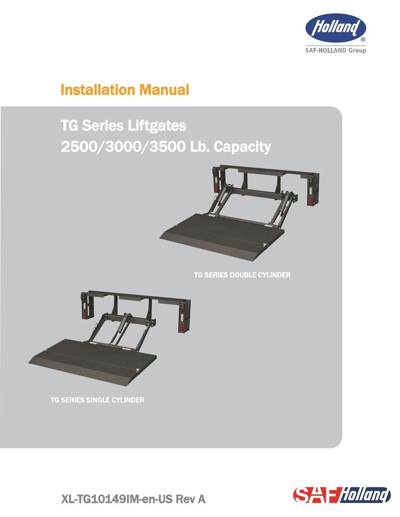
Holland TG Series installation manual

