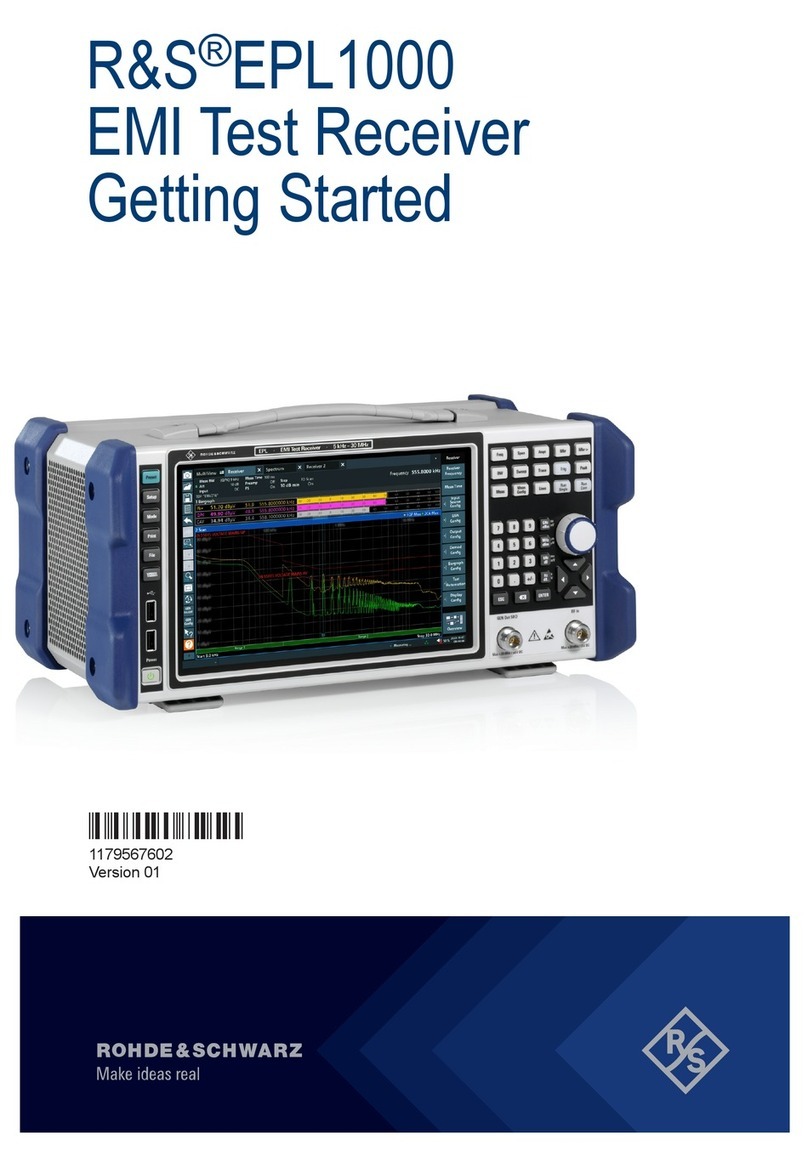
Rohde & Schwarz S4200 User manual

R&S®S4200
R&S®EU4200C
VHF Compact Receiver
Operating Manual
Operating Manual
6174.8456.02 – 01

The Operating Manual describes the following R&S®S4200 EU4200C VHF Compact
Receiver models and options:
●6144.7800.02
●6144.7800.12
●6162.4521.02 (GS4202-EUC) Option Key E1-Interface
●6162.4644.02 (GS4203-EUC) Option Key VoIP
●6174.7620.02 (GS4205-EUC) Option Key Voice Recorder
●6174.7689.02 (GS4206-EUC) Option Key 7 VoIP Sessions
●6174.7720.02 (GS4207-EUC) Option Key Simultaneous Transmission Detection
●6164.7092.02 (GS4208-EUC) Option Key Scan Mode
●DS4200V R11.2x
6164.7286.0x (DS4200V SW-CD R11.2x) Radio SW Package
6164.7263.0x (DS4200V R11.2x) Bin-File
The software contained in this product makes use of several valuable open source
software packages. For information, see the "Open Source Acknowledgment" on the
software CD-ROM.
Rohde & Schwarz would like to thank the open source community for their valuable
contribution to embedded computing.
© 2018 Rohde & Schwarz GmbH & Co. KG
Mühldorfstr. 15, 81671 München, Germany
Phone: +49 89 41 29 - 0
Fax: +49 89 41 29 12 164
Internet: www.rohde-schwarz.com
Subject to change – Data without tolerance limits is not binding.
R&S®is a registered trademark of Rohde & Schwarz GmbH & Co. KG.
Trade names are trademarks of their owners.
Throughout this manual, products from Rohde & Schwarz are indicated without the ®symbol, e.g. R&S®S4200 is indicated as
R&S S4200.

R&S EU4200C
0.1 6174.8456.02-01
O V E R V I E W
1
User Information
General Features, Explanation of a Model, Required Power Supply, Design,
Functioning, General Data, Accessories, Storage
2
Preparation for Use
Safety Precautions, Unpacking and Checking, Installation into a 19" Rack, Basis
Cabling, Switching On/Off, Mechanical Interface Description, Function Test
3
Operation
Control Elements and Interfaces, Introduction, Configuring with the R&S ZS 4200,
Local Control (Local Mode), Remote Control (Remote Mode), Main/Standby
Operation (1:1) in Analog and VoIP Mode, External Automatic Filters, External
Automatic Filters with R&S Protocol, In-Band Signaling, RSSI Output
Characteristic, ACARS Mode (External Modem), Best Signal Selection, Audio via
E1 Interface (Optional), Radio in VDL Mode 2, Audio via VoIP (Optional),
Simultaneous Transmission Detection (Optional), Channel Scanning Software
(Optional), Software Download
4
Malfunction
Visual Inspection, Troubleshooting
5
Maintenance
Scheduled Maintenance, Fan Maintenance, Cleaning
6
Technical Information
Specifications, Interface Description, Remote Control Commands
7
Index
8
Appendix

R&S EU4200C
6174.8456.02-01 0.2

R&S EU4200C
0.3 6174.8456.02-01
Table of Contents
1User Information..................................................................................1.1
1.1 General Features..........................................................................................................1.1
1.2 Explanation of a Model................................................................................................1.1
1.3 Required Personnel.....................................................................................................1.2
1.4 Required Power Supply...............................................................................................1.2
1.5 Design ...........................................................................................................................1.3
1.6 Functioning...................................................................................................................1.4
1.6.1 Block Diagram................................................................................................................1.4
1.6.2 Functions Description ....................................................................................................1.5
1.7 General Data.................................................................................................................1.6
1.8 Accessories..................................................................................................................1.6
1.9 Storage..........................................................................................................................1.6
2Preparation for Use .............................................................................2.1
2.1 Safety Precautions.......................................................................................................2.1
2.2 Unpacking and Checking............................................................................................2.2
2.3 Installation into a 19" Rack.........................................................................................2.3
2.3.1 Installation of Two Radios..............................................................................................2.3
2.3.2 Installation with Blank Panel ..........................................................................................2.4
2.4 Basis Cabling ...............................................................................................................2.5
2.4.1 Rear Cabling ..................................................................................................................2.5
2.4.2 Front Cabling..................................................................................................................2.8
2.5 Switching On/Off..........................................................................................................2.9
2.6 Mechanical Interface Description...............................................................................2.9
2.7 Function Test..............................................................................................................2.10
3Operation..............................................................................................3.1
3.1 Control Elements and Interfaces................................................................................3.2
3.1.1 Front View......................................................................................................................3.2
3.1.2 Rear View.......................................................................................................................3.3
3.2 Introduction ..................................................................................................................3.4
3.2.1 Control Interfaces...........................................................................................................3.4
3.2.2 Modes of Control............................................................................................................3.5
3.2.2.1 Non-Controlled Mode.....................................................................................................3.5
3.2.2.2 Remote Mode.................................................................................................................3.6
3.2.2.3 Local Mode.....................................................................................................................3.7
3.2.2.4 Service Mode .................................................................................................................3.8
3.3 Configuring with the R&S ZS 4200.............................................................................3.9
3.3.1 Factory Default Settings.................................................................................................3.9

R&S EU4200C
6174.8456.02-01 0.4
3.3.2 Meaning of Parameters................................................................................................3.14
3.3.3 CBIT Type Configuration .............................................................................................3.24
3.4 Local Control (Local Mode).......................................................................................3.24
3.4.1 Overview of Operation .................................................................................................3.25
3.4.2 Making Entries from the Keypad..................................................................................3.26
3.4.2.1 Numeric Keys...............................................................................................................3.26
3.4.2.2 Cursor Keys .................................................................................................................3.26
3.4.2.3 MENU Key ...................................................................................................................3.27
3.4.2.4 ENTER Key..................................................................................................................3.27
3.4.2.5 ESC Key.......................................................................................................................3.27
3.4.2.6 SQ Key.........................................................................................................................3.28
3.4.2.7 LOC Key.......................................................................................................................3.30
3.4.3 Screen Display.............................................................................................................3.31
3.4.3.1 Start Display.................................................................................................................3.31
3.4.3.2 Boot Display.................................................................................................................3.31
3.4.3.3 Standard Operating Display.........................................................................................3.32
3.4.3.4 Main Menu Display ......................................................................................................3.33
3.4.3.5 Display Settings and Volume Control ..........................................................................3.34
3.4.4 Indication via LEDs ......................................................................................................3.36
3.4.5 Calling and Changing Menus.......................................................................................3.37
3.4.6 Setting Parameters ......................................................................................................3.39
3.4.6.1 Toggling a Setting ........................................................................................................3.39
3.4.6.2 Selecting Settings ........................................................................................................3.40
3.4.6.3 Entering Numeric Parameters......................................................................................3.41
3.4.7 Overview of All Menus and Functions..........................................................................3.43
3.4.7.1 MAIN Menu ..................................................................................................................3.43
3.4.7.2 OPERATION Menu......................................................................................................3.44
3.4.7.3 TIME/DATE Menu........................................................................................................3.47
3.4.7.4 MEASUREMENT Menu ...............................................................................................3.47
3.4.7.4.1 RX PARAMETER Menu...............................................................................................3.48
3.4.7.4.2 SUPPLY Menu.............................................................................................................3.48
3.4.7.4.3 TEMPERATURE Menu................................................................................................3.49
3.4.7.4.4 OPERATING HOURS Menu........................................................................................3.49
3.4.7.5 CBIT STATUS Menu....................................................................................................3.50
3.4.7.6 INVENTORY Menu ......................................................................................................3.52
3.4.7.7 CONFIGURATION Menu.............................................................................................3.54
3.4.7.7.1 IP ADDRESS Menu .....................................................................................................3.55
3.4.7.7.2 FREQUENCY BLOCK Menu .......................................................................................3.60
3.4.7.7.3 DISPLAY SETTINGS Menu.........................................................................................3.61
3.4.7.7.4 RX THRESHOLDS Menu ............................................................................................3.64
3.4.7.7.5 OPTIONS Menu...........................................................................................................3.66
3.4.7.7.6 AUDIO DELAY Menu...................................................................................................3.67
3.4.7.7.7 AUDIO INTERFACE Menu ..........................................................................................3.68
3.5 Remote Control (Remote Mode) via LAN ................................................................3.69
3.6 Main/Standby Operation (1:1) in Analog and VoIP Mode.......................................3.70
3.6.1 Introduction/Overview ..................................................................................................3.70
3.6.1.1 Behavior of the Main/Standby Configuration with Power On.......................................3.72
3.6.1.2 Behavior at Remote Control.........................................................................................3.73
R&S EU4200C
0.5 6174.8456.02-01
3.6.1.3 Behavior in Case of Device Errors...............................................................................3.74
3.6.1.4 Behaviour in VoIP mode ..............................................................................................3.74
3.6.2 Cabling (Analog) ..........................................................................................................3.75
3.6.3 Configuration................................................................................................................3.75
3.6.4 Cabling (VoIP)..............................................................................................................3.76
3.6.5 Limitations/Notes..........................................................................................................3.78
3.7 External Automatic Filters ........................................................................................3.79
3.7.1 Telsa External Automatic Filter....................................................................................3.79
3.7.1.1 Introduction/Overview ..................................................................................................3.79
3.7.1.2 Cabling.........................................................................................................................3.79
3.7.1.3 Configuration................................................................................................................3.80
3.7.1.4 Limitations/Notes..........................................................................................................3.80
3.7.2 R&S External Automatic Filter .....................................................................................3.80
3.7.2.1 Introduction/Overview ..................................................................................................3.80
3.7.2.2 Cabling.........................................................................................................................3.81
3.7.2.3 Configuration................................................................................................................3.81
3.7.2.4 Limitations/Notes..........................................................................................................3.81
3.7.3 External Automatic Filters with R&S Protocol..............................................................3.82
3.7.3.1 Introduction/Overview ..................................................................................................3.82
3.7.3.2 Cabling.........................................................................................................................3.82
3.7.3.3 Configuration................................................................................................................3.83
3.7.3.4 Limitations/Notes..........................................................................................................3.83
3.8 In-Band Signaling.......................................................................................................3.84
3.8.1 Introduction/Overview ..................................................................................................3.84
3.8.2 Configuration................................................................................................................3.85
3.8.2.1 In-Band Signaling of SQ with Different Audio Tones...................................................3.85
3.8.2.2 Audio In-Band Tones for RSSI Signaling.....................................................................3.85
3.8.2.3 In-Band Signaling of STD with Different Audio Tones.................................................3.85
3.9 RSSI Output Characteristic.......................................................................................3.86
3.9.1 Introduction/Overview ..................................................................................................3.86
3.9.2 Configuration................................................................................................................3.87
3.9.3 Limitations/Notes..........................................................................................................3.88
3.10 ACARS Mode (External Modem)...............................................................................3.88
3.10.1 Introduction/Overview ..................................................................................................3.88
3.10.2 Cabling.........................................................................................................................3.88
3.10.3 Configuration................................................................................................................3.89
3.10.4 Limitations/Notes..........................................................................................................3.90
3.11 Best Signal Selection ................................................................................................3.91
3.11.1 Introduction/Overview ..................................................................................................3.91
3.11.2 Cabling.........................................................................................................................3.92
3.11.3 Configuration................................................................................................................3.93
3.11.4 Limitations/Notes..........................................................................................................3.93
3.12 Audio via E1 Interface (Optional) .............................................................................3.94
3.12.1 Introduction/Overview ..................................................................................................3.94
3.12.2 Cabling.........................................................................................................................3.95

R&S EU4200C
6174.8456.02-01 0.6
3.12.3 Configuration................................................................................................................3.95
3.12.4 Limitations/Notes..........................................................................................................3.96
3.12.5 Parallel Operation of the Analog and E1 Audio Interfaces ..........................................3.96
3.13 Radio in VDL Mode 2 .................................................................................................3.97
3.13.1 Introduction/Overview ..................................................................................................3.97
3.13.2 Cabling.........................................................................................................................3.97
3.13.3 Configuration................................................................................................................3.98
3.13.4 Limitations/Notes..........................................................................................................3.99
3.14 Audio via VoIP (Optional)........................................................................................3.100
3.14.1 Introduction/Overview ................................................................................................3.100
3.14.2 Cabling.......................................................................................................................3.101
3.14.3 Configuration..............................................................................................................3.101
3.14.4 Limitations/Notes........................................................................................................3.101
3.14.5 VoIP Information on Standard Operation Screen ......................................................3.102
3.14.6 VoIP Connections ......................................................................................................3.103
3.14.7 VoIP Connection Establishment ................................................................................3.104
3.14.8 AM Voice Functionality with VoIP Interface...............................................................3.105
3.14.9 Parallel Operation of the Analog and VoIP Audio Interfaces.....................................3.105
3.15 Simultaneous Transmission Detection (Optional) ...............................................3.106
3.16 Channel Scanning Function (Optional) .................................................................3.107
3.17 Software Download..................................................................................................3.109
4Malfunction...........................................................................................4.1
4.1 Visual Inspection..........................................................................................................4.1
4.1.1 Cabling Check................................................................................................................4.1
4.1.2 Checking the LED State.................................................................................................4.2
4.1.3 Checking the CBIT State ...............................................................................................4.3
4.2 Troubleshooting...........................................................................................................4.4
4.2.1 RX CBIT Events.............................................................................................................4.4
4.2.2 Unexpected Radio Restart...........................................................................................4.11
5Maintenance.........................................................................................5.1
5.1 Scheduled Maintenance..............................................................................................5.1
5.2 Fan Maintenance..........................................................................................................5.3
5.3 Cleaning........................................................................................................................5.4
6Technical Information .........................................................................6.1
6.1 Specifications...............................................................................................................6.1
6.2 Interface Description ...................................................................................................6.1
6.2.1 AC Input X1....................................................................................................................6.1
6.2.2 DC Input/Battery Input X2..............................................................................................6.2
6.2.3 RX Input X8....................................................................................................................6.3
6.2.4 Ethernet –LAN Remote Control X9...............................................................................6.4
6.2.5 RX Audio Basic X10.......................................................................................................6.5
6.2.6 RX Audio Extended X11 ................................................................................................6.6

R&S EU4200C
0.7 6174.8456.02-01
6.2.7 RS-422 –Host Interface Port X12 (Reserved) ..............................................................6.8
6.2.8 RX E1 –Communication Data Connector X13..............................................................6.9
6.2.9 USB Device Connector X20.........................................................................................6.10
6.2.10 Headphone Connector X23 .........................................................................................6.10
6.3 Remote Control Commands .....................................................................................6.11
7Index.....................................................................................................7.1
8Appendix ..............................................................................................8.1

R&S EU4200C
6174.8456.02-01 0.8

R&S EU4200C
0.9 6174.8456.02-01
Table of Figures
Fig. 1.1 Modules of the R&S EU4200C receiver..........................................................................1.3
Fig. 1.2 Block diagram. ................................................................................................................1.4
Fig. 2.1 Installation of two radios. ................................................................................................2.3
Fig. 2.2 Installation with blank panel............................................................................................2.4
Fig. 2.3 Rear cabling....................................................................................................................2.6
Fig. 2.4 Front cabling. ..................................................................................................................2.8
Fig. 3.1 Front view........................................................................................................................3.2
Fig. 3.2 Rear view. .......................................................................................................................3.3
Fig. 3.3 Non-controlled mode.......................................................................................................3.5
Fig. 3.4 Remote mode..................................................................................................................3.6
Fig. 3.5 Local mode......................................................................................................................3.7
Fig. 3.6 Service mode. .................................................................................................................3.8
Fig. 3.7 Overview of operation. ..................................................................................................3.25
Fig. 3.8 Keypad..........................................................................................................................3.26
Fig. 3.9 Squelch behavior. .........................................................................................................3.29
Fig. 3.10 R&S Series 4200 logo...................................................................................................3.31
Fig. 3.11 Boot display...................................................................................................................3.31
Fig. 3.12 Standard operating display. ..........................................................................................3.32
Fig. 3.13 Main menu display. .......................................................................................................3.33
Fig. 3.14 Volume control display..................................................................................................3.34
Fig. 3.15 Brightness setting display. ............................................................................................3.34
Fig. 3.16 Contrast setting display.................................................................................................3.35
Fig. 3.17 Indication via LEDs. ......................................................................................................3.36
Fig. 3.18 Main menu. ...................................................................................................................3.37
Fig. 3.19 Submenu.......................................................................................................................3.38
Fig. 3.20 Toggling a setting..........................................................................................................3.39
Fig. 3.21 Selecting settings..........................................................................................................3.40
Fig. 3.22 Frequency entry. ...........................................................................................................3.42
Fig. 3.23 MAIN menu. ..................................................................................................................3.43
Fig. 3.24 OPERATION menu.......................................................................................................3.44
Fig. 3.25 ICAO channeling / frequency pairing. ...........................................................................3.45
Fig. 3.26 Possible combinations of mode/spacing/offset VHF.....................................................3.46
Fig. 3.27 Supported frequency ranges.........................................................................................3.46
Fig. 3.28 TIME / DATE menu.......................................................................................................3.47
Fig. 3.29 MEASUREMENT menu................................................................................................3.47

R&S EU4200C
6174.8456.02-01 0.10
Fig. 3.30 RX PARAMETER menu................................................................................................3.48
Fig. 3.31 SUPPLY menu..............................................................................................................3.48
Fig. 3.32 TEMPERATURE menu.................................................................................................3.49
Fig. 3.33 OPERATING HOURS menu.........................................................................................3.49
Fig. 3.34 CBIT STATUS menu.....................................................................................................3.50
Fig. 3.35 RX CBIT STATUS.........................................................................................................3.51
Fig. 3.36 INVENTORY menu. ......................................................................................................3.52
Fig. 3.37 INVENTORY menu: Display format..............................................................................3.53
Fig. 3.38 CONFIGURATION menu..............................................................................................3.54
Fig. 3.39 IP ADDRESS menu. .....................................................................................................3.55
Fig. 3.40 IP Configuration −RX module......................................................................................3.55
Fig. 3.41 IPv4 configuration. ........................................................................................................3.56
Fig. 3.42 IPv4 address setting......................................................................................................3.56
Fig. 3.43 IPv4 gate address setting. ............................................................................................3.57
Fig. 3.44 IPv4 netmask setting.....................................................................................................3.57
Fig. 3.45 IPv6 configuration. ........................................................................................................3.58
Fig. 3.46 IPv6 address setting......................................................................................................3.58
Fig. 3.47 IPv6 gate address setting. ............................................................................................3.59
Fig. 3.48 Indication of frequency blocking ranges. ......................................................................3.60
Fig. 3.49 DISPLAY SETTINGS menu..........................................................................................3.61
Fig. 3.50 Brightness setting..........................................................................................................3.61
Fig. 3.51 Contrast setting.............................................................................................................3.62
Fig. 3.52 Screen saver timeout setting. .......................................................................................3.62
Fig. 3.53 Load default values setting. ..........................................................................................3.63
Fig. 3.54 Saved values setting.....................................................................................................3.63
Fig. 3.55 RX THRESHOLDS Menu. ............................................................................................3.64
Fig. 3.56 RSSI squelch threshold setting.....................................................................................3.65
Fig. 3.57 S/N squelch threshold...................................................................................................3.66
Fig. 3.58 OPTIONS Menu............................................................................................................3.66
Fig. 3.59 AUDIO DELAY Menu....................................................................................................3.67
Fig. 3.60 AUDIO INTERFACE Menu. ..........................................................................................3.68
Fig. 3.61 Radio control via LAN. ..................................................................................................3.69
Fig. 3.62 Receiver in Main/Standby configuration. ......................................................................3.71
Fig. 3.63 Active device.................................................................................................................3.72
Fig. 3.64 Inactive device. .............................................................................................................3.72
Fig. 3.65 Device in local mode (LOC) activation state On. ..........................................................3.73
Fig. 3.66 Device in remote control mode activation state AUTO.................................................3.73
Fig. 3.67 Main/Standby status after booting and main/standby switchover.................................3.74

R&S EU4200C
0.11 6174.8456.02-01
Fig. 3.68 Main/Standby cabling....................................................................................................3.75
Fig. 3.69 Main/Standby cabling in VoIP mode.............................................................................3.77
Fig. 3.70 Telsa external automatic filter connection. ...................................................................3.79
Fig. 3.71 R&S External automatic filter connection. ....................................................................3.81
Fig. 3.72 External automatic filter with R&S Protocol connection................................................3.82
Fig. 3.73 Tone used for RSSI signal quality.................................................................................3.84
Fig. 3.74 RSSI output type −R&S Standard. ..............................................................................3.86
Fig. 3.75 RSSI output type −User defined..................................................................................3.87
Fig. 3.76 ACARS mode cabling. ..................................................................................................3.88
Fig. 3.77 ACARS mode activation. ..............................................................................................3.89
Fig. 3.78 Active device in the ACARS mode................................................................................3.90
Fig. 3.79 Radio 1 has a stronger receive signal, no switchover audio signal..............................3.91
Fig. 3.80 Radio 2 receives a stronger signal, audio signal is switched from radio 1 to 2 ............3.92
Fig. 3.81 Cabling for best signal selection. ..................................................................................3.92
Fig. 3.82 Radio operation via E1 interface...................................................................................3.95
Fig. 3.83 VDL Mode 2 cabling for split-site configuration. ...........................................................3.97
Fig. 3.84 VDL Mode 2 activation..................................................................................................3.98
Fig. 3.85 Active device in VDL Mode 2........................................................................................3.99
Fig. 3.86 VoIP cabling................................................................................................................3.101
Fig. 3.87 VoIP Connections. ......................................................................................................3.103
Fig. 3.88 VoIP Connection establishment..................................................................................3.105
Fig. 3.89 State chart of channel scanning function....................................................................3.108
Fig. 3.90 MMI display during scan .............................................................................................3.108
Fig. 3.91 Software download via LAN........................................................................................3.109
Fig. 3.92 Software download via USB. ......................................................................................3.109
Fig. 4.1 Checking the LED state. .................................................................................................4.2
Fig. 4.2 Events related to internal restart triggers......................................................................4.13
Fig. 4.3 Validation result mask...................................................................................................4.14
Fig. 5.1 Test connection of TCXO adjustment.............................................................................5.1
Fig. 5.2 Removing the front panel cover......................................................................................5.2
Fig. 6.1 AC input X1.....................................................................................................................6.1
Fig. 6.2 DC input/battery input X2................................................................................................6.2
Fig. 6.3 RX input X8.....................................................................................................................6.3
Fig. 6.4 Ethernet –LAN remote control X9..................................................................................6.4
Fig. 6.5 RX audio basic X10.........................................................................................................6.5
Fig. 6.6 RX audio extended X11..................................................................................................6.6
Fig. 6.7 RS-422 –Host interface port X12 (reserved). ................................................................6.8
Fig. 6.8 RX E1 −Communication data connector X13................................................................6.9

R&S EU4200C
6174.8456.02-01 0.12
Fig. 6.9 USB device connector X20. ..........................................................................................6.10
Fig. 6.10 Headphone connector X23. ..........................................................................................6.10
Last Page of Chapter 0\\Last Page of Chap ter 0 "Radio".doc

Für Betrieb im Europäischen Wirtschaftsraum (EWR) und zivilen Einsatz.
Hinweis gemäß dem Funkanlagengesetz (FuAG) und der Europäischen Richtlinie 2014/53/EU:
Dieses Produkt darf innerhalb des EWR nicht uneingeschränkt betrieben werden, da der verwendete Fre-
quenzbereich auf nicht harmonisierten Bändern erfolgt. Nationale Vorschriften / Genehmigungen sind zu
beachten. Das Gerät ist 4 Wochen vor Inverkehrbringen bei der jeweils zuständigen nationalen Behörde
für die Frequenzhoheit zu notifizieren. Informationen hierzu im Internet unter folgender Adresse:
http://ec.europa.eu/growth/sectors/electrical-engineering/red-directive_en
For operation in the European Economic Area (EEA) and for civil use.
Note pursuant to the German Radio Equipment Act and the European Directive 2014/53/EU:
Operation of this product within the EEA is subject to restrictions since the frequency bands used are not
harmonized. National provisions / authorizations shall be complied with. The product shall be notified to
the competent national frequency management authority four weeks before the product is put on the mar-
ket. For more information refer to:
http://ec.europa.eu/growth/sectors/electrical-engineering/red-directive_en
Pour une exploitation dans l’Espace Économique Européen (EEE) et une utilisation civile.
Note selon la loi allemande sur les équipements radio ainsi que la Directive europé-
enne 2014/53/UE :
L’exploitation de ce produit au sein de l’EEE est soumise à restriction, les bandes de fréquence utilisées
n’étant pas harmonisées. Respecter les prescriptions et autorisations nationales en vigueur. Le produit
doit être notifié quatre semaines avant la mise en circulation auprès de l‘autorité nationale compétente de
la gestion des fréquences. Pour plus d’informations voir :
http://ec.europa.eu/growth/sectors/electrical-engineering/red-directive_en
6190.0733.05 ─ 02
(Ëè7Q5)
0682


This manual suits for next models
9
Table of contents
Other Rohde & Schwarz Receiver manuals

Rohde & Schwarz
Rohde & Schwarz 890 Series User manual

Rohde & Schwarz
Rohde & Schwarz R&S EPL1000 User manual

Rohde & Schwarz
Rohde & Schwarz EMI Test ReceiverESCI User manual

Rohde & Schwarz
Rohde & Schwarz PR100 User manual

Rohde & Schwarz
Rohde & Schwarz ESL3 User manual

Rohde & Schwarz
Rohde & Schwarz EB200 User manual

Rohde & Schwarz
Rohde & Schwarz R&S ESW User manual

Rohde & Schwarz
Rohde & Schwarz EK 895 User manual

Rohde & Schwarz
Rohde & Schwarz EB510 User manual

Rohde & Schwarz
Rohde & Schwarz ESRP EMI User manual