Rohde & Schwarz EB510 User manual

R&S® EB510
HF Monitoring Receiver
Getting Started
Getting Started
(Xé×V2)
4091.7338.02 ─ 01
Radiomonitoring & Radiolocation

This manual describes the following models and options:
●R&S®EB510 HF Monitoring Receiver 4091.7009.02 (without front control panel)
●R&S®EB510 HF Monitoring Receiver 4091.7009.03 (with front control panel)
The firmware of the R&S EB510 makes use of several valuable open source software packages. Please
refer to the "Open Source Acknowledgement" document (4072.8561.02) for a summary of the packages and
the verbatim license texts.
Rohde & Schwarz would like to thank the open source community for their valuable contribution to embedded
computing.
© 2011 Rohde & Schwarz GmbH & Co. KG
Muehldorfstr. 15, 81671 Munich, Germany
Phone: +49 89 41 29 - 0
Fax: +49 89 41 29 12 164
E-mail: [email protected]
Internet: http://www.rohde-schwarz.com
Printed in Germany – Subject to change – Data without tolerance limits is not binding.
R&S® is a registered trademark of Rohde & Schwarz GmbH & Co. KG.
Trade names are trademarks of the owners.
The following abbreviations are used throughout this manual: R&S®EB510 is abbreviated as R&S EB510.

Contents
R&S® EB510
3Getting Started 4091.7338.02 ─ 01
Contents
1Preparation for Use...............................................................5
1.1 Specific Safety Instructions.................................................................5
1.2 Setup......................................................................................................6
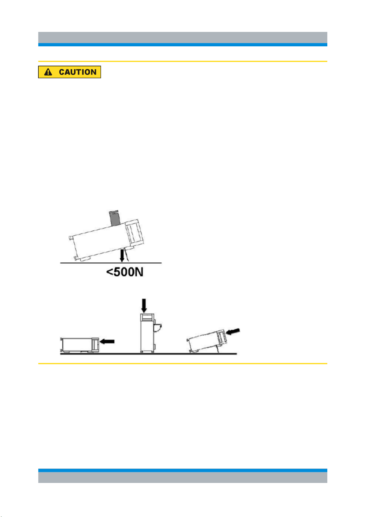
1.2.1 Bench Operation.....................................................................................6
1.2.2 Rack Mounting........................................................................................8
1.2.3 In-vehicle Mounting.................................................................................8
1.2.4 EMI Protective Measures........................................................................8
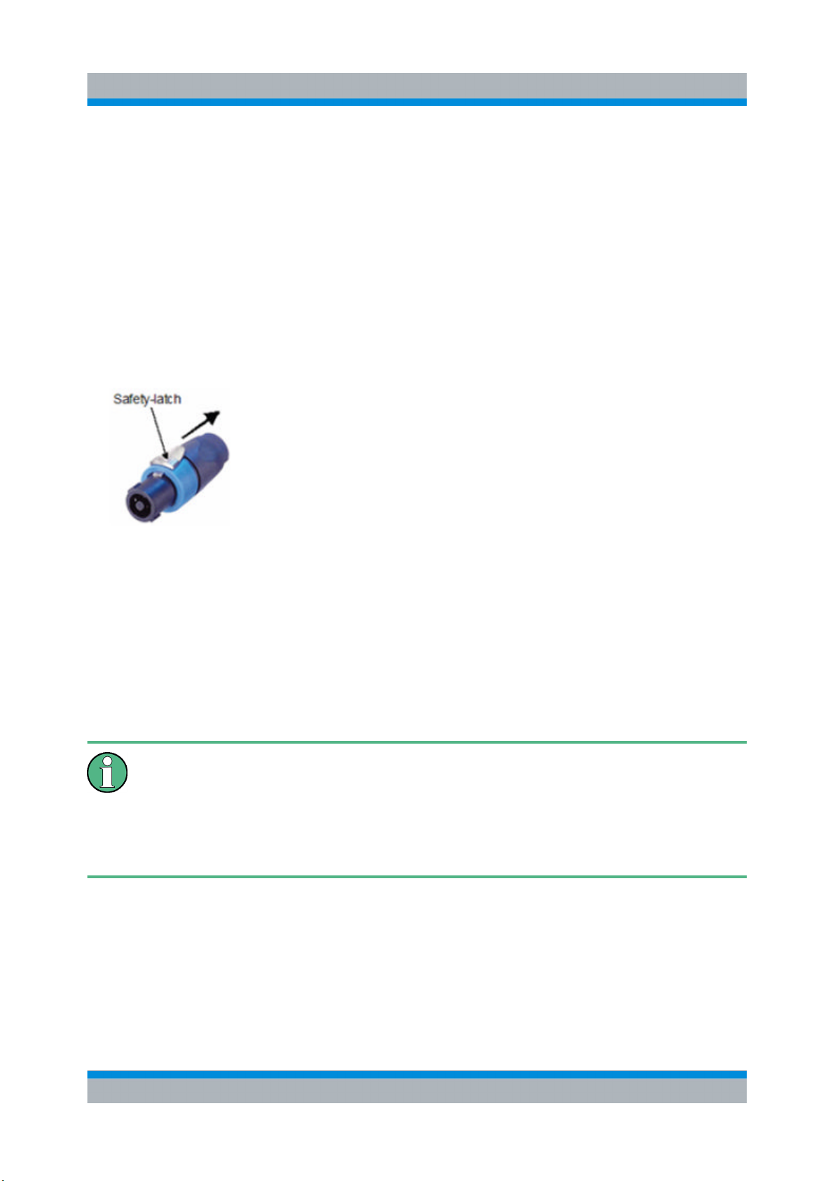
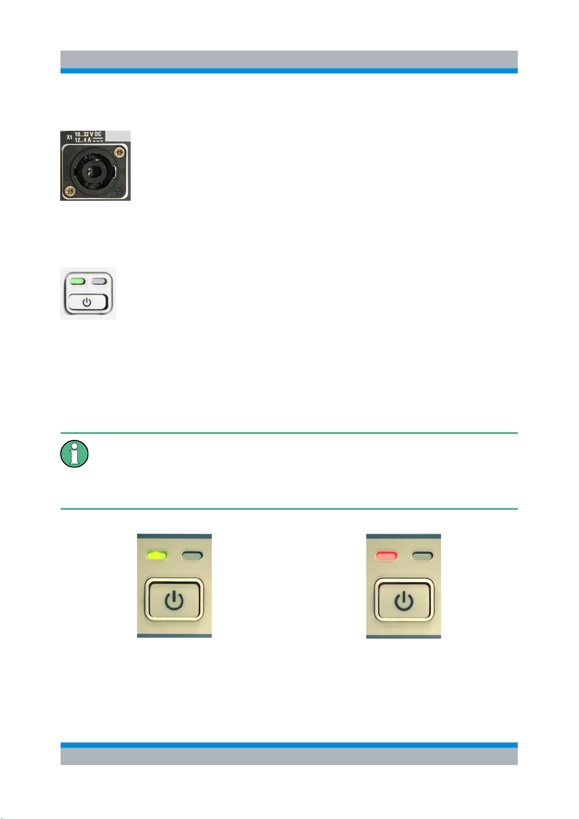
1.2.5 Connecting the R&S EB510 to the Power Supply..................................8
1.2.6 Power On and Off.................................................................................10
1.2.7 STANDBY and READY.........................................................................10
1.2.8 Connecting External Accessories.........................................................11
2Operation..............................................................................12
2.1 Front-Panel Tour.................................................................................12
2.1.1 EB510 with front control panel..............................................................12
2.1.2 EB510 without front control panel.........................................................14
2.2 Rear-Panel Tour..................................................................................16
2.3 Graphical User Interface (GUI)...........................................................18
2.3.1 GUI Layout............................................................................................18
2.3.2 Turning on the R&S EB510 for the First Time......................................20
2.3.3 Online Help...........................................................................................32
3Maintenance.........................................................................37
3.1 Cleaning...............................................................................................37
3.2 Storing and Packing...........................................................................37
3.3 Test Points...........................................................................................37

Contents
R&S® EB510
4Getting Started 4091.7338.02 ─ 01
4Software and Firmware Update..........................................39
4.1 Retrieve Firmware and GUI Versions................................................39
4.2 Receiver Firmware and GUI Update for EB510 with front control
panel.....................................................................................................40
4.2.1 Preparations..........................................................................................41
4.2.2 Update Procedure.................................................................................43
4.3 Receiver Firmware Update for EB510 without front control panel
..............................................................................................................48
4.3.1 Preparations..........................................................................................49
4.3.2 Firmware Update Using Update32 Tool................................................50
4.4 GUI Installation for Remote Access..................................................54
4.4.1 Preparations..........................................................................................54
4.4.2 Installation Procedure...........................................................................55
4.5 Changing the IP Address...................................................................59
4.5.1 Using Update32 Tool............................................................................59
4.5.2 Using GUI (EB510 with front control panel or Remote Access GUI)
..............................................................................................................61

Preparation for Use
R&S® EB510
5Getting Started 4091.7338.02 ─ 01
1 Preparation for Use
This section describes the basic steps to be taken when setting up the R&S EB510
for the first time.
1.1 Specific Safety Instructions
General safety instructions
Please follow the basic safety instructions included in this documentation as
well as the instructions for setup and connection to prevent personal injury or
damage to the R&S EB510. This is of particular importance when you use the
R&S EB510 for the first time.
The following safety instructions apply in particular:
●IEC 364
●VDE 0100
●DIN 57100
These safety regulations deal with the following aspects:
●Prevention of accidents
●Protection against overvoltage
●Insulation of equipment
●Grounding
●Characteristics and laying of lines and cables
●Provisions for operational facilities and rooms and systems of a special nature
Specific Safety Instructions

Preparation for Use
R&S® EB510
6Getting Started 4091.7338.02 ─ 01
Setup
Before turning on the R&S EB510, please make sure that the following con-
ditions are fulfilled:
●Covers are in place and all fasteners are tightened.
●Fan openings are unobstructed.
●Signal levels at the input connectors are all within the specified ranges.
●Signal outputs are correctly connected and not overloaded.
●The R&S EB510 is dry and shows no condensation.
Non-observance may cause damage to the R&S EB510 or other devices in
the setup.
The R&S EB510 is supplied completely assembled except for the handles and
mounting brackets, which must be attached by the user.
1.2 Setup
1.2.1 Bench Operation
Equipment cooling
Do not expose the R&S EB510 to humidity. Leave at least 50 mm of empty
space along both side panels in order to ensure proper equipment cooling.
There are no special requirements for desktop use. To facilitate access to the front
panel elements, you should raise the front of the R&S EB510 by folding out its
standing feet.
Setup

Preparation for Use
R&S® EB510
7Getting Started 4091.7338.02 ─ 01
Risk of injury
The feet may fold in if they are not folded out completely or if the R&S EB510
is shifted. The feet may break if they are overloaded. Fold the feet completely
in or completely out to ensure stability of the R&S EB510 and personal safety.
To avoid injuries, never shift the R&S EB510 when its feet are folded out. The
overall load (the R&S EB510's own weight plus that of any devices stacked
on top of it) on the folded-out feet must not exceed 500 N. Place the
R&S EB510 on a stable surface. Secure any devices stacked on top of it
against slipping (e.g. by locking their feet on the top front frame). When the
R&S EB510 is standing on its folded-out feet, do not work under it and do not
put anything under it as this would pose a risk of personal injury or material
damage.
The R&S EB510 can be used in any of the positions shown here.
Setup

Preparation for Use
R&S® EB510
8Getting Started 4091.7338.02 ─ 01
1.2.2 Rack Mounting
Ambient temperature
The R&S EB510 should be used in an area where the ambient temperature
does not exceed –10 °C to +55 °C (EB510 without front control panel) or 0 °C
to 55 °C (EB510 with front control panel), respectively. The R&S EB510 is
fan-cooled and must be installed with sufficient space along the sides to
ensure a free flow of air. Make sure that there is sufficient space for hot air to
escape from the R&S EB510. To ensure sufficient cooling do not attach tele-
scopic rails to the sides of the unit.
1.2.3 In-vehicle Mounting
For use in vehicles, the R&S EB510 can be powered directly from the vehicle's
battery via the DC input.
1.2.4 EMI Protective Measures
In order to avoid electromagnetic interference (EMI), the R&S EB510 may only be
operated when it is closed and all shielding covers are in place. Use only appropriate
shielded signal and control cables with proper termination.
1.2.5 Connecting the R&S EB510 to the Power Supply
Connect the R&S EB510 observing the following sections and instructions for use.
The R&S EB510 is suitable only for DC operation.
1.2.5.1 Connecting to the Power Adapter
The R&S EB510 is connected to the AC supply 100 V to 240 V via an external AC/
DC power adapter and to the socket X1 (10 VDC to 32 VDC) on the rear panel.
Recommended connector: Neutrik® Speakon® NL4FX (see the figure below).
Setup

Preparation for Use
R&S® EB510
9Getting Started 4091.7338.02 ─ 01
Installing the connector:
1. Insert the Speakon® NL4FX connector into socket X1 on the rear panel.
2. Turn the connector clockwise until it is locked in place and secured by the safety
latch.
Removing the connector:
1. Press and chuck back the safety latch of the Speakon® NL4FX connector.
2. Turn the connector counterclockwise and withdraw it.
Fig. 1-1: Speakon® NL4FX
1.2.5.2 Connecting to the DC Source
The R&S EB510 is connected to an external 10 VDC to 32 VDC source (e.g. battery)
via connector X1 on the rear panel. Recommended connector: Neutrik® Speakon®
NL4FX, see chapter 1.2.5.1, "Connecting to the Power Adapter", on page 8.
DC supply voltage
Make sure that the available supply voltage is between 10 V and 32 V.
Observe correct voltage polarity when connecting. Incorrect polarity may blow
the fuse on the DC converter inside the R&S EB510 or damage the
R&S EB510.
Setup

Preparation for Use
R&S® EB510
10Getting Started 4091.7338.02 ─ 01
1.2.6 Power On and Off
The DC power connection X1 is located at the top left corner of the
R&S EB510 rear panel. With the DC power connected, the
R&S EB510 is in STANDBY or READY state, depending on the state
of the STANDBY toggle switch at the front panel of the R&S EB510
when it was last switched off. The standby power is below 0.8 W.
1.2.7 STANDBY and READY
The STANDBY key is located at the bottom left corner of the front
panel. With the DC power connected, press the STANDBY key
briefly to switch the R&S EB510 from the STANDBY to the READY
state and vice versa. In STANDBY state, the amber LED on the right
will turn on and only the power switch circuit is being powered. In this state, it is safe
to remove the DC power and disconnect the R&S EB510 from the AC/DC power
adapter. In READY state, the green LED on the left is on. The R&S EB510 is ready
for operation. All modules are being powered and the
R&S EB510initiates its startup procedure.
EB510 without front control panel
In the case of EB510 without front control panel, the green Power LED dou-
bles as a 'Fail' status LED. In conditions of failure, the LED will turn red instead
of green, as shown in the figures below.
EB510 without front control panel Ready EB510 without front control panel in Failure
mode. Refer to the Troubleshooting section in
the Operating Manual for possible actions to
take.
Setup

Preparation for Use
R&S® EB510
11Getting Started 4091.7338.02 ─ 01
1.2.8 Connecting External Accessories
1.2.8.1 Connecting a Mouse or Keyboard (EB510 with front control panel
only)
You can connect a mouse or keyboard to the USB port on the front
panel of the R&S EB510. The mouse or keyboard will be detected
automatically when connected. If you want to connect both at the
same time, you will need a USB hub. It is safe to connect and disconnect the mouse
and keyboard during a measurement.
1.2.8.2 Setting up a LAN Connection
You can connect a LAN cable to the LAN port (X7) on the rear panel
of the R&S EB510.
To establish a LAN connection, proceed as described below.
1. Refer to chapter 4.5, "Changing the IP Address", on page 59 for the steps
needed to set the R&S EB510’s IP address.
2. Connect a LAN cable to the LAN port. The R&S EB510 has an internal switch
which automatically detects the type of LAN cable connected so you can use
any standard type of LAN cable to establish a network connection with the
R&S EB510 (dedicated or non-dedicated).
Dedicated vs. non-dedicated network connections
There are two methods to establish a LAN connection with the R&S EB510:
●A non-dedicated network (Ethernet) connection from the R&S EB510 to an
existing network. The R&S EB510 is assigned an IP address and can coexist
with a computer and with other hosts on the same network.
●A dedicated network connection between the R&S EB510 and a single com-
puter. The computer must be equipped with a network adapter and is directly
connected to the R&S EB510. The use of hubs, switches or gateways is not
required; however, data transfer is still made using the TCP/IP protocol.
Please refer to the Operating Manual for the steps to retrieve the IP address by
using the SETUP key.
Setup

Operation
R&S® EB510
12Getting Started 4091.7338.02 ─ 01
2 Operation
Basic operation of the R&S EB510 will be described in this chapter. An overview of
the front panel, rear panel and graphical user interface (GUI) is explained below.
This chapter contains most of the information required to access the various con-
figuration options and settings necessary to get you started operating the
R&S EB510.
2.1 Front-Panel Tour
2.1.1 EB510 with front control panel
An overview of the front-panel elements of the EB510 with front control panel is
given in the paragraphs below.
In the following overview the index numbers refer to the labels in the figure above.
1. Standby key with Ready (green) / Standby (amber) LED indicators.
Front-Panel Tour

Operation
R&S® EB510
13Getting Started 4091.7338.02 ─ 01
2. 5.7", 640 x 480 pixels color TFT display.
3. Utility keys.
●ESC terminates an ongoing operation, e.g. by closing a dialog.
●APPL sets the R&S EB510 to a particular application mode -- Receiver, Video,
ITU (optional), Decode (optional).
●MODE changes the R&S EB510 from a Fixed Frequency Mode (FFM) to one of
the scanning modes.
●SETUP provides access to the setup and configuration dialogs.
●MENU provides access to operational functions "Snapshot", "Record", "Pre-
set", "Zoom +", "Zoom -", "Tests", "File" and "Sanitizing".
●MEM provides a shortcut to memory-related dialogs: "Edit", "RCL", "Save" and
"Suppress".
●HELP starts the online help system (see chapter 2.3.3, "Online
Help", on page 32).
●PANEL toggles between panels to make them active for softkey control.
4. Softkeys.
The function of each softkey is dependent on the softkey bar on the display.
5. Receiver Control Keys.
●BW selects the demodulation bandwidth (between 100 Hz and 5 MHz).
●AFC switches automatic frequency control (AFC) ON or OFF.
●DET selects the level measurement mode (AVERAGE, PEAK, FAST or RMS).
●DEMOD selects the demodulation mode (FM, AM, PULS, PM, IQ, ISB, CW,
USB, LSB).
6. Select Rollkey & Control.
●MARK selects the marker function. The rollkey is used to set marker positions
with associated softkeys. Pressing the rollkey toggles marker display.
●ATT allows the rollkey to set the RF attenuation level. Pressing the rollkey tog-
gles between AUTO and manually set attenuation values.
●MGC allows the rollkey to set the demodulation level for amplitude related mod-
ulation schemes. Pressing the rollkey toggles between AUTO (AGC) and MGC.
Gain control has no effect on FM and PM.
●SQU allows the rollkey to set the squelch level. Pressing the rollkey toggles the
squelch activation.
Front-Panel Tour

Operation
R&S® EB510
14Getting Started 4091.7338.02 ─ 01
7. Volume Control Rollkey.
The volume of the speaker and headphones is adjusted with this knob. Pressing
the knob will toggle the speaker mute. Headphones remain active when the speaker
is in mute position.
8. Cursor Left/Right & Main Rollkey.
●Cursor LEFT/RIGHT moves the cursor in input fields and scrolls within lists. It
also step tunes the frequency by half of the span.
●The main ROLLKEY or ROTARY KNOB is a weighted rotary knob which func-
tions primarily as a tuning knob. In certain menus, the main rollkey serves as
up/down key. Pressing the rollkey confirms an entry (equivalent to the ENT key).
9. Data Entry Keys.
●The 0~9 keys allow entry of the corresponding number or alphabet, decimal
point or symbol.
●ENT (Enter) activates the editing mode and also confirms an entry.
10. USB 2.0 Port.
Allows a USB 2.0-compliant mouse, keyboard or storage device to be connected.
Maximum current
The maximum current for the USB port is 500 mA.
11. Headphones Jack.
Allows stereo headphones with a 3.5 mm stereo plug to be connected.
2.1.2 EB510 without front control panel
An overview of the front-panel elements of the EB510 without front control panel is
given in the paragraph below.
Front-Panel Tour

Operation
R&S® EB510
15Getting Started 4091.7338.02 ─ 01
In the following overview, the index numbers refer to the labels in the figure above.
1. Standby key with Ready (green) or Fail (red) and Standby (amber) LED indi-
cators. The Ready LED also serves as Fail LED, as shown in chapter 1.2.7,
"STANDBY and READY", on page 10
2. Headphones Jack.
Allows stereo headphones with a 3.5 mm stereo plug to be connected.
GUI for remote access
A GUI for remote access is available for the Windows XP platform and is
particularly useful for the EB510 without front control panel because it gives
functionality similar to the EB510 with front control panel. Follow the instruc-
tions in chapter 4.4, "GUI Installation for Remote Access", on page 54 to
install the external GUI software. A Windows XP machine connected to the
same network as the EB510 without front control panel, is required.
Front-Panel Tour

Operation
R&S® EB510
16Getting Started 4091.7338.02 ─ 01
2.2 Rear-Panel Tour
The various inputs and outputs located on the rear panel of the R&S EB510 are
briefly explained in the paragraphs below.
In the following overview, the index numbers refer to the labels in the figure above.
1. X1 Power Supply.
Standard Speakon NL4FX socket for DC power input. Socket accepts 10~32 VDC
on pin 1+ and ground on pin 1- of connector. Power requirement as indicated.
2. Antenna Inputs.
X10 / X11 / X12 Antenna inputs for HF band 9 kHz to 32 MHz.
3. X7 LAN Port.
A 10/100/1000Base-T port for remote control via LAN.
4. Miscellaneous I/O.
●X13 REF IN BNC input for synchronizing with an external 10 MHz reference
frequency normal.
Rear-Panel Tour

Operation
R&S® EB510
17Getting Started 4091.7338.02 ─ 01
●X14 REF OUT BNC output provides a 10 MHz reference frequency normal for
synchronization of other devices. Frequency normal dependent on selected
internal or external reference.
●X15 GPS/TR IN BNC input for an external 1 sec trigger pulse, e.g. from a GPS
device.
5. AUX / AUX Audio.
●X3 AUX AUDIO is a 25-pin D-Sub female connector with the output of different
audio signals.
●X4 AUX is a 25-pin D-Sub female connector for controlling external antenna
switching units.
6. Video Output.
X8 VIDEO A, X9 VIDEO B SMA outputs provide analog I-Q baseband or AM and
FM demodulated signal for further processing. These outputs also can be switched
to output-controlled analog intermediate frequency (IF) in two channels with an
adjustable carrier frequency of 0 Hz to 70 MHz.
7. Serial Interfaces – EIA 232D Compatible.
●X5 COM2, 9-pin D-Sub male connector.
●X6 COM1, 9-pin D-Sub male connector.
X5 and X6 can be used for serial GPS devices according to the NMEA0183 stand-
ard. Use this connector for an external GPS device to determine the location and
the exact time of the R&S EB510.
8. Grounding Post for Earth / Chassis Ground.
Signal Interfaces
All I/O, RF, signal interfaces (X3-X6, X8-X15) must be operated with double
shielded cables.
Interface X7 LAN
A CAT7 LAN cable must be used for this Gigabit capable interface.
Rear-Panel Tour

Operation
R&S® EB510
18Getting Started 4091.7338.02 ─ 01
2.3 Graphical User Interface (GUI)
This chapter provides a short description of the graphical user interface of the
R&S EB510.
2.3.1 GUI Layout
Following is an overview of the layout and individual elements of the graphical user
interface.
In the table below follows the description of the different panels, according to the
panel number indicated in the figure above.
Graphical User Interface (GUI)

Operation
R&S® EB510
19Getting Started 4091.7338.02 ─ 01
Panel
No.
Description
1Basic receiver parameters
2Icons
Shows one or several of the following icons to indicate a specific function or condition of
the R&S EB510:
Compass connected.
GPS connected.
Configuration: using external reference.
Receiver overflow.
Recording in progress.
Marker selected.
Speaker is off.
Speaker is on.
Audio signal is available in stereo at current frequency.
The R&S EB510 is not locked.
The R&S EB510 is locked by another client. Access is not possible.
The R&S EB510 is locked. Only the current operator can make changes
(exclusive write access).
A critical error occurred in the receiver. The "Test Points" dialog will provide
more information.
3Mode
Shows the current receiver mode, e.g. FFM, PScan, FScan or MScan. The current date
and time is also shown.
4Frequency
Shows the current receiver frequency. As this is the most important parameter, it is dis-
played much larger than the remaining parameters.
5Measurement parameters
Shows the basic measurement parameters (level and frequency offset; numerically and
bar graph). The squelch level is also shown by means of an indicating marker in the bar
graph.
Graphical User Interface (GUI)

Operation
R&S® EB510
20Getting Started 4091.7338.02 ─ 01
Panel
No.
Description
6Panel area
The panel area is used for displaying the various panels of the R&S EB510 (spectrum
and waterfall are shown).
●The light cyan color of the scale bar indicates that the panel is in focus: softkey
operations affect the panel (see below). A marker to show the squelch level relative
to the trace level is also displayed.
●The dark blue bar around the demodulation frequency marking denotes the band-
width being demodulated.
●On the right side, the rainbow colored bar indicates the color that is mapped to the
corresponding spectrum level for the waterfall display.
7Softkeys
Softkeys change their function based on the panel that is in focus. They show panel-
dependent parameters, e.g. "SPAN" and "STEP" for IF panel and IF Waterfall panel.
Other softkeys are only related to e.g. RF panel, RF Waterfall panel etc.
Softkeys can be related to hardkeys: they can e.g. provide selection options in case one
of the Utility keys is pressed or in case DET or MARK is pressed.
Softkeys can also provide the option for selecting a unit (kHz, MHz etc) e.g. when keying-
in a frequency, they can provide additional functionality when editing input fields in dia-
logs, e.g. backspace or caps lock. Finally they can serve as shortcut keys for navigating
through tables in dialogs, e.g. in the "Memory Setup" dialog or through the "Help" pages.
2.3.2 Turning on the R&S EB510 for the First Time
Upon power on, the R&S EB510 is always defaulted into the Fixed Frequency
Receiver Mode (reference to Operating Manual). In this mode, the R&S EB510
behaves as a normal receiver with the screen as shown in chapter 2.3.1, "GUI
Layout", on page 18. Upon power on the speaker will always be muted.
2.3.2.1 Unmute the speaker
The volume of the speaker and headphones is adjusted with the
VOLUME KNOB. Pressing the knob will mute / unmute the speaker.
Headphones remain active when the speaker is in mute position.
Graphical User Interface (GUI)
This manual suits for next models
2
Table of contents
Other Rohde & Schwarz Receiver manuals

Rohde & Schwarz
Rohde & Schwarz EK 895 User manual

Rohde & Schwarz
Rohde & Schwarz S4200 User manual

Rohde & Schwarz
Rohde & Schwarz PR100 User manual

Rohde & Schwarz
Rohde & Schwarz ESRP EMI User manual

Rohde & Schwarz
Rohde & Schwarz 890 Series User manual

Rohde & Schwarz
Rohde & Schwarz R&S EPL1000 User manual

Rohde & Schwarz
Rohde & Schwarz R&S ESW User manual

Rohde & Schwarz
Rohde & Schwarz ESL3 User manual

Rohde & Schwarz
Rohde & Schwarz EB200 User manual

Rohde & Schwarz
Rohde & Schwarz EMI Test ReceiverESCI User manual