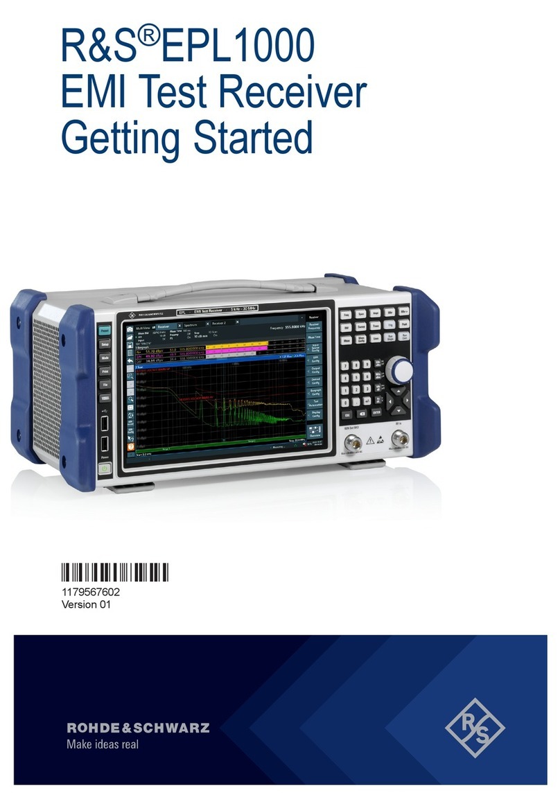
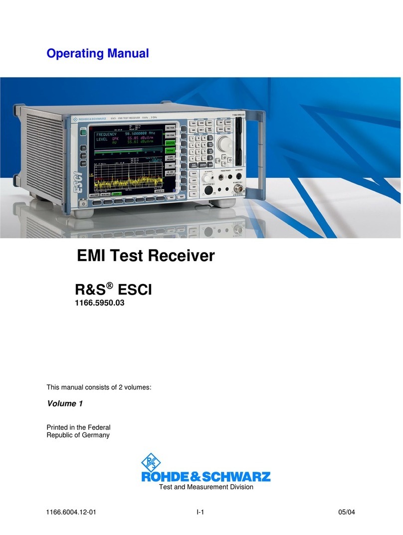
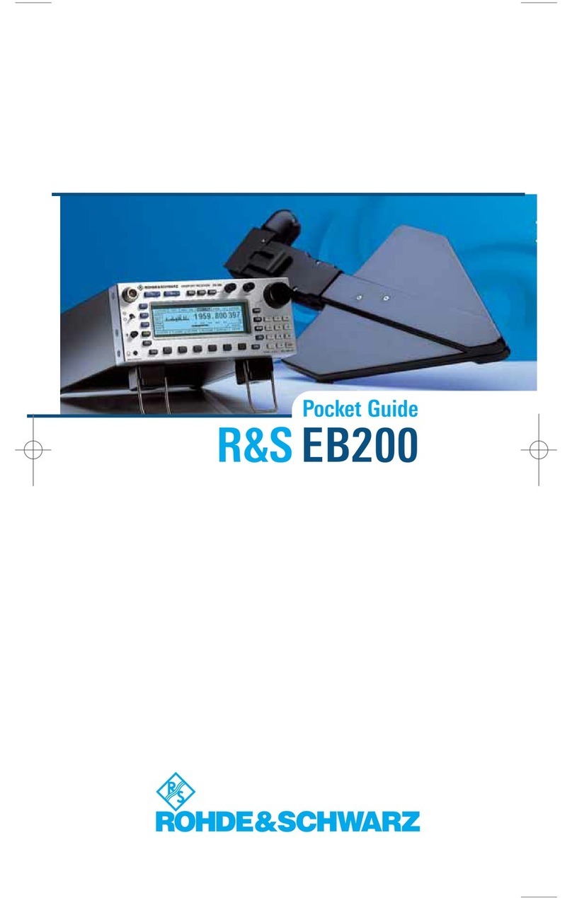
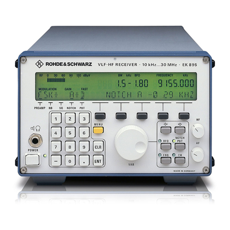
Rohde & Schwarz 890 Series User manual

User Manual
Radiocommunications Systems Division
6164.0171.02 - 01
R&S®Series 890
VLF-HF Receivers
R&S®EK895/ R&S®EK896
User Manual

The documentation describes following models:
R&S®EK895 — 6057.8996.xx — SW Version: 04.00 — DSP Version: 02.00
R&S®EK896 — 6038.2509.xx — SW Version: 04.00 — DSP Version: 02.00
©03/2010 Rohde & Schwarz GmbH & Co. KG
81671 Munich, Germany
Printed in Germany — Subject to change — Data without tolerances: order of magnitude only
The R&S logo, Rohde & Schwarz and R&S are registered trademarks of Rohde & Schwarz GmbH & Co. KG and their subsidiaries.
Trade names are trademarks of the owners.

6164.0717.02_01
-C.1 / C.2 -
KONFORMITÄTSERKLÄRUNG gemäß dem Gesetz über Funkanlagen und Telekommunikationsendeinrichtungen (FTEG)
und der Richtlinie 1999/5/EG (R&TTE)
DECLARATION OF CONFORMITY in accordance with the Radio and Telecommunications Terminal Equipment Act (FTEG) and Directive
1999/5/EC (R&TTE Directive)
Zertifikat-Nr.: / Certificate No.: 2006-77
Hiermit wird bescheinigt, dass die Funkanlage
This is to certify that the radio equipment
Gerätetyp
Equipment Type
Materialnummer
Stock No.
Benennung
Designation
EK895 6057.8996.02/.12/.14/.17/.37 VLF-HF-Digital-Empfänger
VLF-HF Digital Receiver
Geräteklasse: / Equipment class: 1.7 (Receive-only radio equipment)
inklusive ihrer in der Anlage aufgelisteten Bestückungsoptionen bei bestimmungsgemäßer Verwendung den
grundlegenden Anforderungen des § 3 und den übrigen einschlägigen Bestimmungen des FTEG (Artikel 3 der
R&TTE) entspricht. *)
including all options and variants listed in the enclosure complies with the essential requirements of §3 and the other relevant provisions of
the FTEG (Article 3 of the R&TTE Directive), when used for its intended purpose. *)
•Gesundheit und Sicherheit gemäß § 3 (1) 1 (Artikel 3 (1) a))
•Health and safety requirements pursuant to § 3 (1) 1 (Article 3(1) a))
•Schutzanforderungen in Bezug auf die elektromagn. Verträglichkeit § 3 (1) 2, Artikel 3 (1) b))
•Protection requirements concerning electromagnetic compatibility § 3(1)(2), (Article 3(1)(b))
•Maßnahmen zur effizienten Nutzung des Funkfrequenzspektrums
•Measures for the efficient use of the radio frequency spectrum
•Luftschnittstelle bei Funkanlagen gemäß § 3(2) (Artikel 3(2))
•Air interface of the radio systems pursuant to § 3(2) (Article 3(2))
Angewendete harmonisierte Normen:
Harmonized standards applied:
EN 60950-1 : 2001
ETSI EN 300373-1 V1.2.1 (2002-10) *)
ETSI EN 300373-2 V1.1.1 (2004-01)
ETSI EN 300373-3 V1.1.1 (2004-01)
Einhaltung der grundlegenden Anforderungen auf andere Art
und Weise (hierzu verwendete Standards/Spezifikationen):
Other means of proving conformity with the essential requirements
(standards/specifications used):
---
*) Einschränkungen zu Kapitel 7.5 und 7.6 siehe Bedienhandbuch.
*) For limitations regarding chapters 7.5 and 7.6 see operating manual.
Anbringung des CE-Zeichens ab: 2006 / Affixing the EC conformity mark as from 2006
ROHDE & SCHWARZ GmbH & Co. KG
Mühldorfstr. 15, D-81671 München
München, den 18. Januar 2007 Zentrales Qualitätsmanagement MF-QZ / Radde
Munich, 2007-01-18 Central Quality Management
6164.0717.02_01
-C.3 / C.4 -
KONFORMITÄTSERKLÄRUNG gemäß dem Gesetz über Funkanlagen und Telekommunikationsendeinrichtungen (FTEG)
und der Richtlinie 1999/5/EG (R&TTE)
DECLARATION OF CONFORMITY in accordance with the Radio and Telecommunications Terminal Equipment Act (FTEG) and Directive
1999/5/EC (R&TTE Directive)
Anlage zu Zertifikat-Nr.: 2006-77
Enclosure to Certificate No.:
ROHDE & SCHWARZ GmbH & Co. KG
Mühldorfstr. 15, D-81671 München
München, den 18. Januar 2007 Zentrales Qualitätsmanagement MF-QZ / Radde
Munich, 2007-01-18 Central Quality Management
Gerätetyp
Equipment Type
Materialnummer
Stock No.
Benennung
Designation
FK890H1 6007.7750.02 Preselection Unit
GM893 6051.8494.03 Broadband IF Output
GC890 6007.7809.02 BCD-Interface
GB899 6037.3501.03 Remote Control Unit
UX895 6077.0261.02 IF conversion
GH890 6007.6054.02 TTY Line Current Source
GB899 6037.3501.02/03 Remote Control Unit


6164.0717.02_01
-C.5 / C.6 -
KONFORMITÄTSERKLÄRUNG gemäß dem Gesetz über Funkanlagen und Telekommunikationsendeinrichtungen (FTEG)
und der Richtlinie 1999/5/EG (R&TTE)
DECLARATION OF CONFORMITY in accordance with the Radio and Telecommunications Terminal Equipment Act (FTEG) and Directive
1999/5/EC (R&TTE Directive)
Zertifikat-Nr.: / Certificate No.: 2006-37
Hiermit wird bescheinigt, dass die Funkanlage
This is to certify that the radio equipment
Gerätetyp
Equipment Type
Materialnummer
Stock No.
Benennung
Designation
EK896 6038.2509.12/.14/.17/.37 VLF-HF-Digital-Suchempfänger
VLF-HF Digital Search Receiver
Geräteklasse: / Equipment class: 1.7 (Receive-only radio equipment)
inklusive ihrer in der Anlage aufgelisteten Bestückungsoptionen bei bestimmungsgemäßer Verwendung den
grundlegenden Anforderungen des § 3 und den übrigen einschlägigen Bestimmungen des FTEG (Artikel 3 der
R&TTE) entspricht. *)
including all options and variants listed in the enclosure complies with the essential requirements of §3 and the other relevant provisions of
the FTEG (Article 3 of the R&TTE Directive), when used for its intended purpose. *)
•Gesundheit und Sicherheit gemäß § 3 (1) 1 (Artikel 3 (1) a))
•Health and safety requirements pursuant to § 3 (1) 1 (Article 3(1) a))
•Schutzanforderungen in Bezug auf die elektromagn. Verträglichkeit § 3 (1) 2, Artikel 3 (1) b))
•Protection requirements concerning electromagnetic compatibility § 3(1)(2), (Article 3(1)(b))
•Maßnahmen zur effizienten Nutzung des Funkfrequenzspektrums
•Measures for the efficient use of the radio frequency spectrum
•Luftschnittstelle bei Funkanlagen gemäß § 3(2) (Artikel 3(2))
•Air interface of the radio systems pursuant to § 3(2) (Article 3(2))
Angewendete harmonisierte Normen:
Harmonized standards applied:
EN 60950-1 : 2001
ETSI EN 300373-1 V1.2.1 (2002-10) *)
ETSI EN 300373-2 V1.1.1 (2004-01)
ETSI EN 300373-3 V1.1.1 (2004-01)
Einhaltung der grundlegenden Anforderungen auf andere Art
und Weise (hierzu verwendete Standards/Spezifikationen):
Other means of proving conformity with the essential requirements
(standards/specifications used):
---
*) Einschränkungen zu Kapitel 7.5 und 7.6 siehe Bedienhandbuch.
*) For limitations regarding chapters 7.5 and 7.6 see operating manual.
Anbringung des CE-Zeichens ab: 2006 / Affixing the EC conformity mark as from 2006
ROHDE & SCHWARZ GmbH & Co. KG
Mühldorfstr. 15, D-81671 München
München, den 18. Januar 2007 Zentrales Qualitätsmanagement MF-QZ / Radde
Munich, 2007-01-18 Central Quality Management

6164.0717.02_01
-C.7 / C.8 -
KONFORMITÄTSERKLÄRUNG gemäß dem Gesetz über Funkanlagen und Telekommunikationsendeinrichtungen (FTEG)
und der Richtlinie 1999/5/EG (R&TTE)
DECLARATION OF CONFORMITY in accordance with the Radio and Telecommunications Terminal Equipment Act (FTEG) and Directive
1999/5/EC (R&TTE Directive)
Anlage zu Zertifikat-Nr.: 2006-37
Enclosure to Certificate No.:
ROHDE & SCHWARZ GmbH & Co. KG
Mühldorfstr. 15, D-81671 München
München, den 18. Januar 2007 Zentrales Qualitätsmanagement MF-QZ / Radde
Munich, 2007-01-18 Central Quality Management
Gerätetyp
Equipment Type
Materialnummer
Stock No.
Benennung
Designation
FK890H1 6007.7750.02 Preselection Unit
GM893 6051.8494.03 Broadband IF Output
GC890 6007.7809.02 BCD-Interface
GB899 6037.3501.03 Remote Control Unit
UX895 6077.0261.02 IF conversion
GH890 6007.6054.02 TTY Line Current Source
GB899 6037.3501.02/03 Remote Control Unit


HF RECEIVERS R&S®EK 895 / R&S®EK 896
User Manual
6164.0717.02_01
-E.1 / E.2 -
Notice:
The HF Receivers R&S®EK 895 / R&S®EK 896 were tested in
accordance with ETSI EN 300 373-1 V1.2.1 (2002-10) with the
following deviations:
1. ETSI EN 300 373-1 / 7.5 Temperature Tests
In accordance with the R&S®EK895 / R&S®EK896 specification, the device
was tested at -10 °C to +45 °C (ETSI EN 300 373-1 demands a temperature
range of -15 °C to +55 °C for internally mounted equipment).
2. ETSI EN 300 373-1 / 7.6 Corrosion Test
The device must be operated in a room where it is protected against the effects
of corrosive environment.


V L F >H F R E C E I V E R S
f
R & S E K 8 9 5 / R & S E K 8 9 6
User Manual
C A U T I O N
When switching the VLF>HF Receiver EK 895 on at an ambient
temperature of >25!∞C, allow approx. 15 minutes for the receiver to
reach its full serviceability.
6164.0717.02_01
>N.1 / N.2 >


V L F > H F R E C E I V E R S
f
E K 8 9 5 / E K 8 9 6
User Manual
Definitions
BIT In the BIT (built>in test) it is checked whether all modules of
the basic unit are installed and operative. If required, error
messa es are output which may also inform on the operatin
status of the installed options. In addition, the Tx and Rx paths
are checked. The BIT is initiated either throu h switch>on or on
purpose durin operation by pressin softkey BIT in the MAIN
menu.
Check In appropriate measurements by means of the specified test
equipment proper functionin of a unit or module is estab>
lished.
CM In CM (continuous monitorin ) all important equipment func>
tions are permanently monitored. This check is automatic. Er>
ror messa es are output followin which the operator can ini>
tiate the BIT to localize the fault.
Disconnect Pull off connector.
Examine In case of trouble the unit / module or components such as e. .
connectors, are to be thorou hly checked for obvious me>
chanical dama e.
Functional check This means that components / modules / units are checked for
proper functionin while installed.
Hazardous volta es Volta es > 30 V
rms
or 50 V
pp
(AC) or 50 V (DC)
Make sure Ascertain whether all mentioned requirements are met or all
measures are taken to establish the required condition.
Open Access is to be ained to the unit / module by observin the
iven instructions and safety precautions.
Perfect condition This means that a component / module / unit has to be in a
state which does not ive cause to complaints.
Replacement In case of trouble the replacement of modules is carried out in
order to localize and eliminate the fault.
Replace Components / modules / units which > due to dama e and / or
other defects > no lon er meet the respective requirements or
components / modules / units which durin troubleshootin
were identified as the cause of fault, are to be replaced.
Simple measurements In addition to the BIT, the operatin condition of the overall
equipment can be checked directly by measurin the transmit
and receive functions. If the iven nominal values are not
reached, the entire transceiver must be sent for repair.
6045.6712.12.07
> B.1 >

V L F > H F R E C E I V E R S
f
E K 8 9 5 / E K 8 9 6
User Manual
Visual examination This is a visual inspection of the outer appearance and com>
pleteness of a component / module / unit without manual in>
terference by the examiner. This does not include the neces>
sary preparations and finishin work such as e. . openin and
closin of covers or similar.
6045.6712.12.07
> B.2 >

V L F > H F R E C E I V E R S
f
E K 8 9 5 / E K 8 9 6
User Manual
Notices
The three different notices used in this User
Manual have the following meaning:
W A R N I N G
This heading is used to indicate that in>
accurate observance or nonobservance
of instructions or methods can cause
injury or even fatal accidents or during
an operation described hazardous ma>
terial can be set free in the unit or sys>
tem.
A U T I O N
This heading is used to indicate that inaccurate
observance or nonobservance of instructions
or methods can cause damage to the unit.
Note:
This heading is used to draw the reader's atten>
tion to a particular fact.
This User Manual contains the following 'Warn>
ing':
W A R N I N G
Do not open the cover unless the VLF>
HF receiver is disconnected from mains
voltage!
6045.67 2. 2.07
> H.1 / H.2 >


V L F > H F R E C E I V E R S
f
E K 8 9 5 / E K 8 9 6
User Manual
f
Application
User Information
Purpose of the Manual
This Manual provides all information the operators and service staff need to maintain levels 1 and
2 of repairs.
It contains all necessary information and instructions concerning the installation, putting into
operation and control of the unit, plus troubleshooting instructions down to module level. In case
of trouble this allows straightforward error locali ation as well as easy replacement of the module
concerned. This permits the unit to be put back into proper working order and operation with
minimum delay.
We re ommend to keep omplete spare units / modules in store.
Measuring Units
In this Manual the basic SI measuring units and units coherently derived from them are used by
preference. In exceptional cases units legally derived from the SI units acc. to DIN 1301 may also be
used.
Symbols
The different symbols used in this Manual have the following meaning:
f
= listing
Æ = steps to be followed
6045.6712.12.07
> Z.1 / Z.2 >

This manual suits for next models
2
Table of contents
Other Rohde & Schwarz Receiver manuals

Rohde & Schwarz
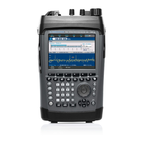
Rohde & Schwarz PR100 User manual

Rohde & Schwarz
Rohde & Schwarz EMI Test ReceiverESCI User manual

Rohde & Schwarz
Rohde & Schwarz ESL3 User manual

Rohde & Schwarz
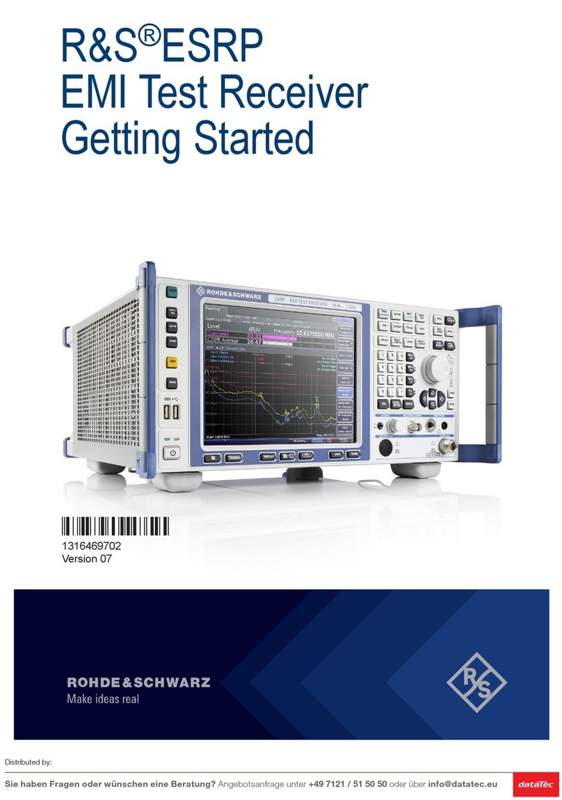
Rohde & Schwarz ESRP EMI User manual

Rohde & Schwarz
Rohde & Schwarz S4200 User manual

Rohde & Schwarz
Rohde & Schwarz R&S ESW User manual

Rohde & Schwarz
Rohde & Schwarz EB200 User manual

Rohde & Schwarz
Rohde & Schwarz R&S EPL1000 User manual

Rohde & Schwarz
Rohde & Schwarz EK 895 User manual

Rohde & Schwarz
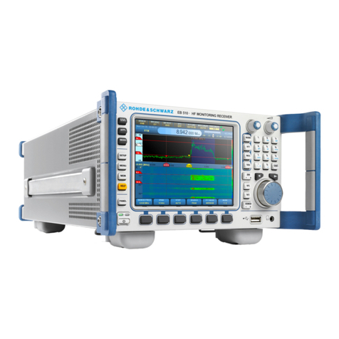
Rohde & Schwarz EB510 User manual