www.ti.com
2SLOU403C–March 2015–Revised June 2018
Submit Documentation Feedback
Copyright © 2015–2018, Texas Instruments Incorporated
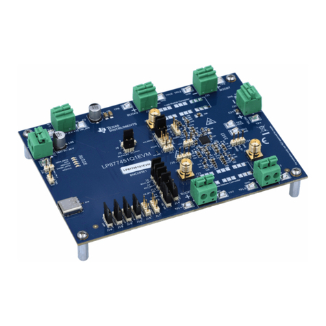
DRV2700EVM High Voltage Piezo Driver Evaluation Kit
Contents
1 Getting Started............................................................................................................... 6
1.1 Evaluation Module Operating Parameters....................................................................... 6
1.2 Quick Start Board Setup........................................................................................... 7
1.3 Connecting a Load.................................................................................................. 7
2 Overview of EVM ............................................................................................................ 8
2.1 DRV2700............................................................................................................. 8
2.2 Microcontroller (MSP430).......................................................................................... 8
2.3 Power Supply Inputs and Path.................................................................................... 8
2.4 EN and Gain Configuration........................................................................................ 9
2.5 Inputs ............................................................................................................... 10
2.6 Outputs ............................................................................................................. 10
2.7 BST/PVDD Disconnect ........................................................................................... 10
2.8 TRIG Button........................................................................................................ 10
3 EVM Control Software (GUI).............................................................................................. 11
4 Boost Converter ............................................................................................................ 12
4.1 Boost Voltage Setting Resistors................................................................................. 13
4.2 Disconnecting BST/PVDD........................................................................................ 14
4.3 Programming the Boost Current Limit.......................................................................... 14
4.4 Boost Inductor Selection ......................................................................................... 14
4.5 Boost Capacitor Selection........................................................................................ 14
5 PWM, Analog, and Single-Ended Inputs................................................................................ 15
5.1 PWM (AC Coupled) Input Using MSP430 ..................................................................... 15
5.2 PWM (AC Coupled) Input Using AIN ........................................................................... 15
5.3 External Analog (AC Coupled) Input............................................................................ 16
5.4 Single-Ended (DC Coupled) Input .............................................................................. 16
6 Output........................................................................................................................ 19
6.1 Two Terminal Differential Output Configuration (OUT+ – OUT–)........................................... 19
6.2 Two Terminal Single Ended Output Configuration (OUT± to BST/GND) .................................. 19
6.3 Three Terminal Single Ended Output Configuration (BST to OUT± to GND)............................. 20
7 Load Selection.............................................................................................................. 20
8 Filtering and Adapting PWM Waveforms................................................................................ 21
8.1 PWM Input ......................................................................................................... 21
8.2 Filter Selection Criteria ........................................................................................... 22
9 Reference ................................................................................................................... 25
9.1 Schematic .......................................................................................................... 25
9.2 PCB Layout ........................................................................................................ 26
9.3 Bill of Materials .................................................................................................... 28
List of Figures
1 Board Diagram............................................................................................................... 6
2 Power Path Diagram ........................................................................................................ 8
3 Gain = 40.7 dB............................................................................................................... 9
4 Gain = 38.4 dB............................................................................................................... 9
5 Gain = 34.8 dB............................................................................................................... 9
6 Gain = 28.8 dB............................................................................................................... 9
7 GUI Interface................................................................................................................ 11
8 BST Network JP2, JP3, and JP4......................................................................................... 13
9 PWM Signal................................................................................................................. 15
10 Set Reference to External 2.5 V ......................................................................................... 17
11 Floating Reference at 3 Hz and No Load............................................................................... 17
12 Floating Reference at 1 Hz and No Load............................................................................... 17
13 DC Coupled Input Diagram ............................................................................................... 18
