ROJ SUPER ELF X3 User manual

SUPER ELF X3
Operating Instructions for DORNIER looms
INSTRUCTION MANUAL_1219_ENGLISH
Robustness • Reliability • Quality • Productivity • Versatility

WARNING!
-
Condensation could form on the Weft Feeder when it
is moved from the cold environment of
the warehouse to
the warmer environment of the weaving room. Make sure
that it is
completely dry before connecting to power.
-
Provide proper information to the people operating the
weft Feeders.
-
The installation, connection, adjustment, and maintenance of the Weft Feeder has to be
performed by
technically qualified
personnel.
-
The Loom's main power switch MUST be switched
OFF before any replacing
or
connecting
operation.
-
Caution must be taken on the close vicinity of the
Feeder. In normal working condition, it can
start running
without prior warning and the moving parts might
cause
injuries.
-
Repairing any electrical part of the unit has to be carried
out by
Roj
s.r.l
.
authorized personnel.
-
Always
use
proper
spare
parts
and
accessories
supplied
by Roj
s.r.l
.
-
Roj
s.r.l
.
disclaims all responsibility for the
improper use
of the Feeder different from what
described
in the chapter 1. General Information.

SUPER ELF X3
–
Dornier
2
INDEX
page
1. GENERAL INFORMATION
Super Elf X3 description
3
Super Elf X3 Technical Data
3
Pulsar HP brake description
3
Technical data of Pulsar HP
3
Other information about Super Elf X3
3
Features and Characteristics
4
2. SETTING AND CONTROL ELEMENTS
Front control elements
5
Back panel contr
ol elements
6
3. INSTALLATION AND
CONNECTION
Electric connect
ions
7
Diagram connection of the Voltage Su
pply Box
8
4. SETTINGS AND OPERATION
How to set working parameters
9
Insertion length
10
Reserve sensor
10
Filling tensioner (Pulsar HP)
11
Sensors sensitivity settings
13
Maintenance
1
4
Photocells automatic cali
bration
15
Photocells information
15
Weft length adjustment
16
Winding direction and coils pitch adjustment
17
Reserve loading
(Full air threa
ding, only with funnel
)
18
Reserve loading (Half air
threading)
18
5. TROUBLESHOOTING
19
6. SPARE PARTS
Funnel
20
Eyelet holder
20
Pulsar HP
20
Voltage Supply Bo
x
21
Feeder (with Plasma coated Spool body)
22
Feeder (with Chromed coated Spool body)
23

SUPER ELF X3
–
Dornier
3
1.
GENERAL INFORMATION
Super Elf X3 description
SUPER ELF X3
is a Weft Feeder with
yarn separation
and direct
CAN
-
bus
communication
with the Loom
Control. The new Permanent Magnet motor and the
Reserve sensor allow very
fast reaction and accurate yarn storage control on the spool
body. The new and innovative
barrier optical sensors
guarantee best performances in
dust environments and with very
fine
yarns.
Super Elf X3
-
Technical Data
Power
supply by means of the specific
Roj
Control Box
:
100 V dc
–
24 V dc
Weft feeding speed (pattern in advance info)
:
max 2400 m/min
Threading channel
:
4.5 mm
Yarn count range:
6 Nm
-
10 dTex
Noise
level:
< 70 dB A
Weight:
8 kg
Wor
king temperature:
from 10 ° to 40 °C
Storage temperature:
from
–
25 ° to +65 °C
Relative humidity:
max 95% (not condensed)
Pulsar HP brake description
The Pulsar HP device, performs the
following two functions:
Breaking function:
to reduce the tension pick to the weft when the same is
stopped by the
Electromagnet pin. This is to avoid the following problems:
a. weft breakage at the end of the insertion
b. weft loops or slack picks in th
e fabric.
Pull back function:
after the yarn cutting, yarn is pulled back into the nozzle.
This is to avoid that the weft gets tangled in the next weft to be inserted by the
contiguous nozzle.
Technical data of Pulsar HP
Cycles per minute
:
1
.
200
R
eaction time
:
7 ms
Max torque
:
11.5 Ncm
Weft pull back
length
:
max 35 mm
Eyelet's diameter
:
6 mm
Other information about Super Elf X3
The
Part Number (P/N)
and the
Serial Number (S/N)
are printed on the
CE label.

SUPER ELF X3
–
Dornier
4
Features and
Characteristics
o The Weft Feeder can be set for rotation S or Z depending on the yarn
twist.
o Yarn separation is adjustable from 0.7 mm to 2.2 mm.
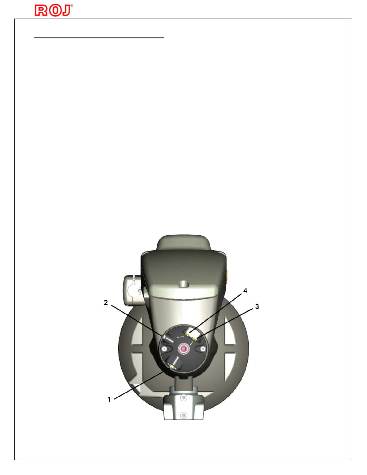
o Coils detection by means of photocells (Barrier system).
o Storage detection with an integrated
photocell (barrier system).
o Input Weft breakage control through a photocell integrated in the Super
Elf X3, or through
external TFE6 weft Stop Motion device.
o Weft length adjustment, by setting the spool body diameter and the
number of coils to be
rel
eased at each insertion.
o Range of weft lengths: from 64 to 672 cm.
Note
: Weft lengths ranging from 87 to 96 cm CANNOT BE MEASURED.
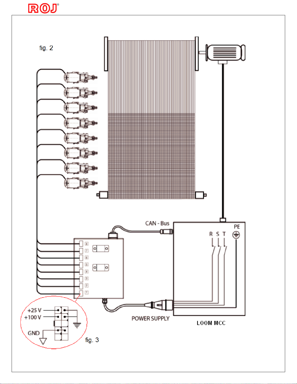
o CAN BUS communication protocol with the loom Control.
o Pulsar HP brake control.
o Full and half weft threading by me
ans of a pneumatic system.
o New Electromagnet design.
o Reserve Storage position Photocell reliable also in dust environments.
o Permanent Magnet motor for more accurate speed control, faster
acceleration, full torque at
all speeds and lower energy
consumption.
o Sealed motor, photocells housing and cable connections are IP63 Water
Proof standard
o New anti
-
balloon design with reclining Funnel simplifies maintenance and
optimizes space requirements for multi
-
color applications.

SUPER ELF X3
–
Dornier
5
2.
SETTING AND
CONTROL ELEMENTS
Front Control elements
1
FUNCTION BUTTON
It activates the Electromagnet and allows the following operations:
a
-
Weft reserve removal.
b
-
New weft reserve loading.
c
-
Release of only one coil when the weft reserve is already on the
Spool Body.
d
-
Photocells calibration
e
-
Reset of the fatal errors without switching OFF the main power.
A
SIGNALING LED
When the weft feeder is powered, the led turns on if no faults are detected.
In case of
problems, the led blinks. Slow blinking in
case of warnings, fast
blinking in case of fatal errors.
B
ADJUSTMENT SCREWS FOR THE ELECTROMAGNET
POSITION
C, D, E
ADJ
USTMENTS SCREWS OF SPOOL BO
DY DIAMETER
(Coil length)
F
PUSH BUTTON FOR SETTING OF WINDING DISC ROTATION
DIRECTION AND COILS
SEPARATION

SUPER ELF X3
–
Dornier
6
Back panel control elements
1
CONNECTION OF AIR LINE INPUT
2
CONNECTION OF AIR LINE FOR FULL AIR THREADING
Full air threading is possible only in combination with Funnel. If the feeder is fitted
with eyelet
holder, or without any balloon
control, this connection must be closed with
relevant plug that it
is supplied with the feeder.
3
HALF THREADING BUTTON
Insert the yarn into the eyelet and press the half threading button (3), whilst lightly
holding the
yarn.
4
FULL THREADING BUTTON
Insert the yarn into the eyelet and press the full threading button (4), whilst lightly
holding the
yarn.

SUPER ELF X3
–
Dornier
7
3.
INSTALLATION AND CONNECTION
Voltage Supply Box and Weft Feeder installation
1.
Fix the Voltage Supply Box to the Stand by means
of the proper
brackets.
Note
:
Minimum distance from the Box to the floor must
be 20 cm. (see fig.
1
)
2.
Install the Weft Feeders on the Stand by means of
the existing clamps.
Note
:
The feeders must be positioned on the stand according to the type of installation. It
is
important that
yarn path is as straight as possible between the Feeders
and the loom
nozzle
s
.
3.
Place the Feeders' cables and the air tubes inside the tunnel of the Stand.
Electric
al
connections
1.
Connect the Feeder's cables to the Voltage Supply Box
by
following the numeric
correspondence to the loom nozzles (Feeder working with the weft threaded in
nozzle 1 must
be connected to the position 1 of the Voltage Supply Box; etc.).
2.
Connect the CAN
BUS cable to the loom (see fig.
2
page 8
).
3.
Feeder's Stand and Creel must be connected to the earth of the loom.
4.
Connect the plug of the 3
-
phase power cord to the socket on the loom main
control cabinet
(MCC). See fig.
2
page 8
.
Warning!
The
connection between the Voltage Supply B
ox and the 3
-
phase power supply
network must always be as stated on the follow
ing page. In this way, the loom
main switch
performs also as main switch
for the Weft Feeders (see fig.
2
page 8
).
Note:
The Voltage
values supplied to the Weft Feeders can be checked on the Voltage
Supply
Box connectors (see fig. 3
page 8
).

SUPER ELF X3
–
Dornier
8

SUPER ELF X3
–
Dornier
9
4.
SETTINGS AND OPERATION
How to set working parameters
1.
Turn the loom main switch ON. The feeders are now supplied with power and
receive
the
setup data from the loom Control (wait for about one minute).
2.
The pulsar calibration cycle is then automatically performed. If no faults occur,
the signaling
led, on the front side of the feeder, remains ON. In case of faults,
the led blinks and a
fault
message is shown on
the loom Dialog panel display.
3.
According to the woven article, adjust the functioning parameters of Super Elf X3
, which
can be set on DORNIER loom Dialog panel (see picture
below).
4
.
Press the icon
to enter the feeder pages.
Note
:
Before switching the loom power ON, always
verify that the pulsar fork
(F)
is free
to move and
therefore avoid:
· Yarn tied to eyelet h
older or any other machine part
· Yarn inser
ted into
the fabric and not cut
The yarn can be kept firmly by loom controlled devices
as these are synchronized
with the Pulsar calibration
function.
T
o
reset the error
"Pulsar not calibrated",
switch the loom OFF, make
sure that the Pulsar fork is
free to move
,
th
e
n switch the
loom
back ON.

SUPER ELF X3
–
Dornier
10
Insertion
length
Note:
the
setting “Insertion Length” is dependent
on
the “Reed width” parameter which is
under the “Weft
Insertion” menu.
It is recommended to make the Feeder operating with the
Drum set to the
wider diameter and releasing the minimum number of coils possible (see
table
below
for reference).
Reserve Sensor
Automatic = ON
Automatic = OFF
When this is set to Automatic = ON, the Reserve Sensor automatically regulates the
take
-
off point at a fixed position.
• Possible setting:
Off, 0, 1, 2
To set the number of coils (windings) to be released by the
Feeder at each pick.
• Possible setting:
2
-
> 16.
• Recommended setting: see note

SUPER ELF X3
–
Dornier
11
Off
-
Automatic position control deactivated
0
-
Autom
atic position control activated
with lower reserv
e storage
1
-
Autom
atic position control activated
with standard reserve storage
2
-
Autom
atic position control activated
with maximum reserve storage
(the take
-
off point is
nearby the stopper pin)
• Recommended setting:
1
Reserve windings
(to be set when Automatic = OFF)
It sets the number of coils to be wound on Spool body when a new Reserve is loaded.
Set the
highest number of coils possible, avoiding them to overlap each other nearby the stopper pin
(t
he reserve has to be over 3/4 of t
he
spool body
length
)
.
• Possible setting:
12
-
> 68.
• Recommended setting: according to the yarn co
unt, set the coils pitch as low
as possible.
Note:
In case of different reserve position between Feeders, set with the same number of
coils
and make them
equal by adjusting the coils pitch.
Filling Tensioner (Pulsar HP)
Stroke
This parameter allows
set
the stroke angle value:
• Possible setting:
off
brake disabled
1
minimum stroke angle
2
low stroke angle
3
middle stroke angle
4
high stroke angle
5
maximum stroke angle
Set here the Yarn type
Possible settings:
fiber
filament < 500dTex
wool
filament > 500dTex
The Pulsar HP will automaticall
y use
the factory
pre
-
settings according to
the chosen yarn
type

SUPER ELF X3
–
Dornier
12
• Recommended setting:
2
it gives a
low reduction of the end
insertion tension peek.
(The yarn speed reduction at the
arrival
is very low).
3
it gives a good reduction of the en
d
insertion tension peek.
(The yarn speed reduction at the
arrival
is low).
4
it gives a very good reduction of the
end
insertion tension peek. The yarn speed
reduction is
very high and the arrival is
very irregular).
Note:
Use the
"1"
and
"5"
values only in extreme cases:
1
-
when the important is to avoid to slow dow
n the yarn at the arrival. (The
reduction of the
end insertion tension peak will be very low).
5
-
to reduce the end insertion tension peek
as much as possible. (The yarn
speed reduction
is very high and the arrival is very irregular).
Duration
This parameter set the duration of braking function.
• Possible setting:
0
the fork reach braking positio
n at same time when the
electromagnet pin stops the yarn at
end of insertion
1
minimum braking anticipation
2
low braking anticipation
3
middle braking anticipation
4
high braking anticipation
5
maximum
braking anticipation
• Recommended setting:
0, 1, 2
for
filament yarns
2, 3, 4, 5
for
fiber yarns
and
wool
Force
This parameter allows the user to choose between 5 force values:
• Possible setting:
0
minimum braking force
1
low braking force
2
middle braking force
3
high braking force
4
maximum braking force
• Recommended setting: Increase the braking force according to yarn size (Yarn count)

SUPER ELF X3
–
Dornier
13
Filling Draw back
This parameter allows
to enable or disable
the yarn filling draw back after yarn
cut. It is
also
possible to choose how large angle to use to pull the yarn back.
• Possible setting:
off
disabled filling draw back
1
minimum angle for draw back
2
middle angle for draw back
3
maximum angle for draw back
• Recommended setting: Use
mostly "
2"
and "
3"
values .
Sensors sensitivity settings
Reaction time of the Feed Sensor
Set the sensitivity for
the photocell
with function as
input yarn break sensor
• Possible setting: 2, 3, 4, 5 and OFF (OFF = Feed Sensor OFF)
• Recommended
setting: 3
Note:
increase the value in case of “false” yarn break stops
Winding sensor
Sets the sensitivity of the photocell which is controlling the outgoing coils.
• Possible setting: normal yarn / fine yarn
• Recommended setting: normal yarn
Reserve
sensor
Sets the sensitivity of the photocell which is controlling Automatic Reserve Position.
• Possible setting: normal yarn / fine yarn
• Recommended setting: normal yarn

SUPER ELF X3
–
Dornier
14
Length correction
Avoids wrong weft length measurement due to the eventual
overlapping of the coils on
the Spool body.
• Possible setting:
ON / OFF
• Recommended setting:
ON
Note:
Set OFF in case of short picks (one coil less)
with
irregular insertion times.
Double yarn sensor
Controls the yarn break by means of an external
sensor (Roj PIEZO sensor TFE6).
• Possible setting:
ON / OFF
Rotation direction
To set the winding direction of the Feeder according to the yarn twist.
• Possible setting:
Z / S
Note:
When changing the winding direction, the coils pitch has to be
changed too.
Maintenance
Calibrate hardware
Not used with Super Elf X3
Stopper / Pulsar test
This test activates a test cycle on the pulsar that will
move the pulsar fork according to the settings in the
Filling tensioner menu. The Stopper
electromagnet is
also activated.
Check reserve sensor
Not used with Super Elf X3

SUPER ELF X3
–
Dornier
15
Photocells automatic calibration
The Super Elf X3 is fitted with an automatic photocells calibration system. Proceed as
follows:
1.
Remove all the yarn from the spool
body, and verify that the photocells glass and
mirrors
are clean (see below)
2.
Press the Reserve push
-
button on the feeder side for about 10 seconds, till the
LED makes
a short blinking than remains steady ON:
at this point
the calibration is
automatical
ly
performed by the feeder SW. Wait a few seconds, that reset the
feeder by switching it OFF,
than back ON. The automatic calibration is needed
when replacing the feeder circuit board or
one of the sensors groups.
Note:
if the calibration procedure is
made with yarn on the spool body, or with glass
-
mirrors
dirty, the feeder can go in alarm “SYSTEM ERROR 4” and it is completely
blocked. To unlock
the feeder, remove the yarn from spool body, or the dust from
glass
–
mirrors, and make the
automatic calibr
ation again. If, after performing correctly
the automatic calibration, the same
error is still displayed on the loom Dialog panel,
proceed as here below described:
-
Check the stopper pin position and distance from the spool body (see page 16)
-
Check the
correct connection of the photocell circuit inside the spool body
-
Replace the top spool body sector (that includes the sensors)
-
Replace the stopper magnet housing
-
Replace the C
PU
board and make a new automatic calibration
Photocells information
The
Super Elf X3 works with an automatic compensation system, to grant same level of
reading signals, even when the dust stats to accumulate on the window glass of the
optical
sensors.
The amount of dust accumulated it is indicated on relevant display page,
as on
example
below:
Note:
this information for the Reserve sensor it is not yet implemented on loom display

SUPER ELF X3
–
Dornier
16
Weft length adjustment
The diameter of the Weft Feeder Spool Body must be set according to the indication
shown
on the loom Dialog panel
display.
Proceed as follows
:
1.
Loosen the screw
B
and raise the Photocells/Electromagnet Group. Fix it.
2.
Loosen the both
C
socket head screws (3 mm socket).
3.
Turn the Winding Disc until the eyelet is in the upper position.
4.
Loosen the
D1
socket
head screw (3 mm socket).
5.
Turn the Winding Disc until the eyelet is in the lower position.
6.
Loosen the
D2
socket head screw (3 mm socket)
7.
Adjust the diameter of the Spool Body by turning the
E socket screw (5 mm
socket screw
with the hole for D1 screw)
in order to move the sectors of the
Winding Group to the
requested reference according to weft length to be
inserted (see page 10).
8.
Turn the Winding Disc until the eyelet is in the lower position.
9.
Tighten the
D1 and D2
socket head screws (3 mm socket) to block the fixed
sectors
(remember to center the hole on the screw head,
points 3 and 5).
10.
Check that the movable sectors are centrally positioned in respect with the fixed
ones.
11.
Tighten the two screws
C
to block the movable sectors.
12.
Turn the Winding Disc and check that no movable sectors get in contact with
the fixed
ones; this is in order to avoid possible damages when the feeders is in
operation. If the
sectors get in contact, use the
C
screws to
adjust the movable
sectors.
13.
Loosen the screw
B
and position the
Photocells/Electromag
net
gro
up
so that the
distance
between the Electromagnet and the
Spool Body i
s about 1
-
1.2 mm (see
picture below
on
the
right
-
use the special gauge supplied
with the
feeder).
14.
Load the reserve as described on page 18.
15.
Start up the loom and check if the length weft
is as required. If it is too long, decrease a bit
the spool body diameter. If it is too short,
increase a bit the diameter.
Note:
Fixing torque
recommended for the
screws
D1, D2
and
C
= 2.3 Nm ± 10%

SUPER ELF X3
–
Dornier
17
Winding direction and coils pitch adjustment
The winding direction (S or Z) must be adjusted according to the yarn
twist. Correspondence
is needed between the motor electric setting and the
mechanical
one of the Spool Body.
Proceed
as follows:
1.
Press the yellow Separation push
-
button
F
placed in front of the Spool Body and
simultaneously turn the Winding Disc until you hear a “click” (the yellow pushbutton is entered
in a slot).
2.
Whil
e keeping pressed this push
-
button, turn the Winding Disc up to the chosen
position (the ceramic eyelet indicates the position). Release the push
-
button.
Note:
The coils pitch must be adjusted according to the yarn count. In case of working
with
Automatic Reserve set to OFF, set the Reserve Windings value on the loom
Dialog panel by
avoiding excessive accumulation of coils in front of the Spool
Body.
3.
Select the winding direction rotation on the loom Dialog panel: the magnet pin
goes up
allowin
g removal of the reserve from the Spool Body. In the meanwhile,
the eyelet of the
Winding Disc moves to the threading position.
4.
Press the start push button
1,
the Electromagnet pin goes down and the weft
reserve is
loaded.

SUPER ELF X3
–
Dornier
18
Reserve loading
(Full threading, only with funnel)
1.
Press the start push
-
button
1
on the side of the feeder for more than 3 seconds: the
Electromagnet pin goes up and the Winding Disc automaticall
y
moves to the threading
position.
2.
Release a few coils from the pack
age and keep the yarn end near the input
threading
eyelet, than press the full threading button
4
to thread the weft through the
feeder body out to
the pulsar (if the old reserve is still on the spool body it will be
automatically blown out).
3.
Press the key in the front of the feeder a second time: the Electromagnet goes
down and
the Feeder loads the reserve.
Weft reserve repair
(Half threading)
If during the Feeder operation, a weft breakage occurs at Feeder's entry, proceed as
follows:
1.
Release a few coils from the package and keep the yarn end near the input
threading
eyelet, than press the half threading button
3,
so that the weft is blown to the
output of the
winding disk without affecting the existing reserve on the Spool Body. Thi
s
operation allows
the weft to be knotted to the existing reserve.
2.
Press the start push
-
button
1
on the front of the feeder in order to reset the weft
breakage
error. The feeder will restore the complete weft reserve.

SUPER ELF X3
–
Dornier
19
5.
TROUBLESHOOTING
Description
All error messages from Super Elf X3 are shown on the display of Loom Dialog panel.
N
ote
:
Details to fault analysis and fault repair are possible to find in the
Dornier
Documentation "Dialog Panel Ergo Weave" in chapter 4 "Messages"
The
Feeder will also give an alarm by means of the signaling LED (see page 4).
The LED is
steady ON during the normal operation of the Feeder.
It is fast flashing in case of Heavy
Alarms (i.e. the feeder cannot continue to work), or it is
slow flashing in case
of Warning
Alarms (i.e. the feeder can continue to work, but some
maintenance or checking
is
required)
In case the loom Control panel will display “ Feeder n. … SYSTEM ERROR 4” please
refer to the Automatic photocells calibration described on page 15.
Table of contents
Other ROJ Weaving manuals