Gex en English
4
b] Never place your hand near the rotating ac-
cessory. Accessory may kickback over your
hand.
.c] Do not position your body in the area where
power tool will move if kickback occurs. Kick-
back will propel the tool in direction opposite to
the wheel’s movement at the point of snagging.
d] Use special care when working corners, sharp
edges, etc. Avoid bouncing and snagging the
accessory. Corners, sharp edges or bouncing
have a tendency to snag the rotating accessory
and cause loss of control or kickback.
e] Do not attach a saw chain woodcarving blade
or toothed saw blade. Such blades create fre-
quent kickback and loss of control over the
power tool.
Safety Warnings Specific for Grinding Oper-
ations
Use only wheel types that are recommended for
your power tool and the specific guard designed
for the selected wheel. Wheels for which the
power tool was not designed cannot be adequately
guarded and are unsafe.
The grinding surface of the centre depressed
wheels must be mounted below the plane of the
guard lip. An improperly mounted wheel that pro-
jects through the plane of the guard lip cannot be
adequately protected.
The guard must be securely attached to the
power tool and positioned for maximum safety,
so the least amount of wheel is exposed to-
wards the operator. The guard helps to protect
operator from broken wheel fragments and acci-
dental contact with wheel and sparks which could
ignite clothing.
Wheels must be used only for recommended ap-
plications.
Always use undamaged wheel flanges that are
of correct size and shape for your selected
wheel. Proper wheel flanges support the wheel
thus reducing the possibility of wheel breakage.
Flanges for cut-off wheels may be different from
grinding wheel flanges.
Do not use worn down wheels from larger power
tools. Wheel intended for larger power tool is not
suitable for the higher speed of a smaller tool and
may burst.
Safety warnings specific for grinding and
sanding operations
Do not use excessively oversized sanding disc pa-
per. Follow manufacturers recommendations,
when selecting sanding paper. Larger sanding pa-
per extending beyond the sanding pad presents a
laceration hazard and may cause snagging, tearing
of the disc or kickback.
Safety Warnings Specific for Polishing Op-
erations
Do not allow any loose portion of the polishing
bonnet or its attachment strings to spin freely.
Tuck away or trim any loose attachment strings.
Loose and spinning attachment strings can entan-
gle your fingers or snag on the workpiece.
Additional safety instructions
Particles generated when working with this ma-
chine may contain substances that can cause can-
cer, allergic reactions, respiratory diseases, birth
defects or other propagation defects. Some of
these substances include: Lead (in paint containing
lead), mineral dust (from bricks, concrete etc.), ad-
ditives used for wood treatment (chromate, wood
preservatives), some wood types (such as oak or
beech dust), metals, asbestos.
The risk depends on for how long the user or nearby
persons are exposed to the substance.
This dust must not be allowed to enter your body.
Do the following to reduce exposure to these sub-
stances:
- Ensure good ventilation of the workplace.
- Wear appropriate protective equipment, such as
respirators able to filter microscopically small
particles.
- To protect your health, wear a suitable
protective mask.
- Always wear protective goggles to protect
against sanding hazards.
- Connect the electric power tool to a suitable ex-
traction system.
- Sweeping or blowing stirs up dust.
- Vacuum or wash the protective clothing. Do not
blow, beat or brush.
Collect the generated particles at the source, avoid
deposits in the surrounding area.
Observe the relevant guidelines for your material,
staff, application and place of application (e.g. oc-
cupational health and safety regulations, dis-
posal).
If potentially explosive or self-igniting dust is pro-
duced during sanding, the machining instructions
issued by the material manufacturer must always
be followed.
Attention: Risk of fire! Avoid overheating the
grinding material and the sander. Always empty
the dust container before taking a break. Swarf in
the filter bag or filter of the extraction system may
self-ignite in unfavorable conditions such as flying
sparks when grinding metals. Particular danger ex-
ists if the swarf is mixed with paint, polyurethane
residue or other chemical materials and the grind-
ing material is hot after long periods of work.
Damaged, eccentric or vibrating tools must not be
used.
There must be no unprotected persons in the ejec-
tion direction of the tool and the immediate vicinity.
Always use an antistatic suction hose with the
power tool. A slight electric shock may cause you to
panic briefly and become distracted, which may re-
sult in an accident.
When the safety clutch responds, switch off the
machine immediately!
Do not overload the motor for a long period. Engine
noise should be regular (not wave-like). Unsteady
engine performance can be perceived acoustically.
Take a break when the machine is heated up
strongly and let it cool down again. To that let the
motor idle at top speed for some time.
Don’t bend the flexible drive shaft!
Start working with the lowest speed in order to get
a feel for the machine.
Don’t put the running motor on the ground! Dirt may
get sucked in and cause damage.
Always use original ROKAMAT abrasives. Foreign
abrasives are not suitable for the speed of the
sander and may break.
Pull the plug out of the socket before making any
adjustments, converting or servicing the machine.
Ensure sufficient cable clearance. Use only exten-
sion cables permitted for outdoor use.
Keep the carry case out of reach of children. Chil-
dren may suffocate or be strangled when playing
with the carry case.
Emission levels
NOTE! Values for the A-weighted sound pressure
level and for the total vibration values can be found
in the “Technical specifications” table at page 9.
The vibration emission level given in this infor-
mation sheet has been measured in accordance
with a standardized test and may be used to com-
pare one tool with another. It may be used for a
preliminary assessment of exposure.
CAUTION! The indicated measurements refer to
new power tools. Daily use causes the noise and vi-
bration values to change.
The declared vibration emission level represents
the main applications of the tool. However, if the
tool is used for different applications, with differ-
ent accessories or poorly maintained, the vibration
emission may differ. This may significantly in-
crease the exposure level over the total working
period. However, if the tool is used for different ap-
plications, with different accessories or poorly
maintained, the vibration emission may differ. This
may significantly decrease the exposure level over
the total working period.
CAUTION! The noise produced during work
may damage your hearing.
Wear ear protection!
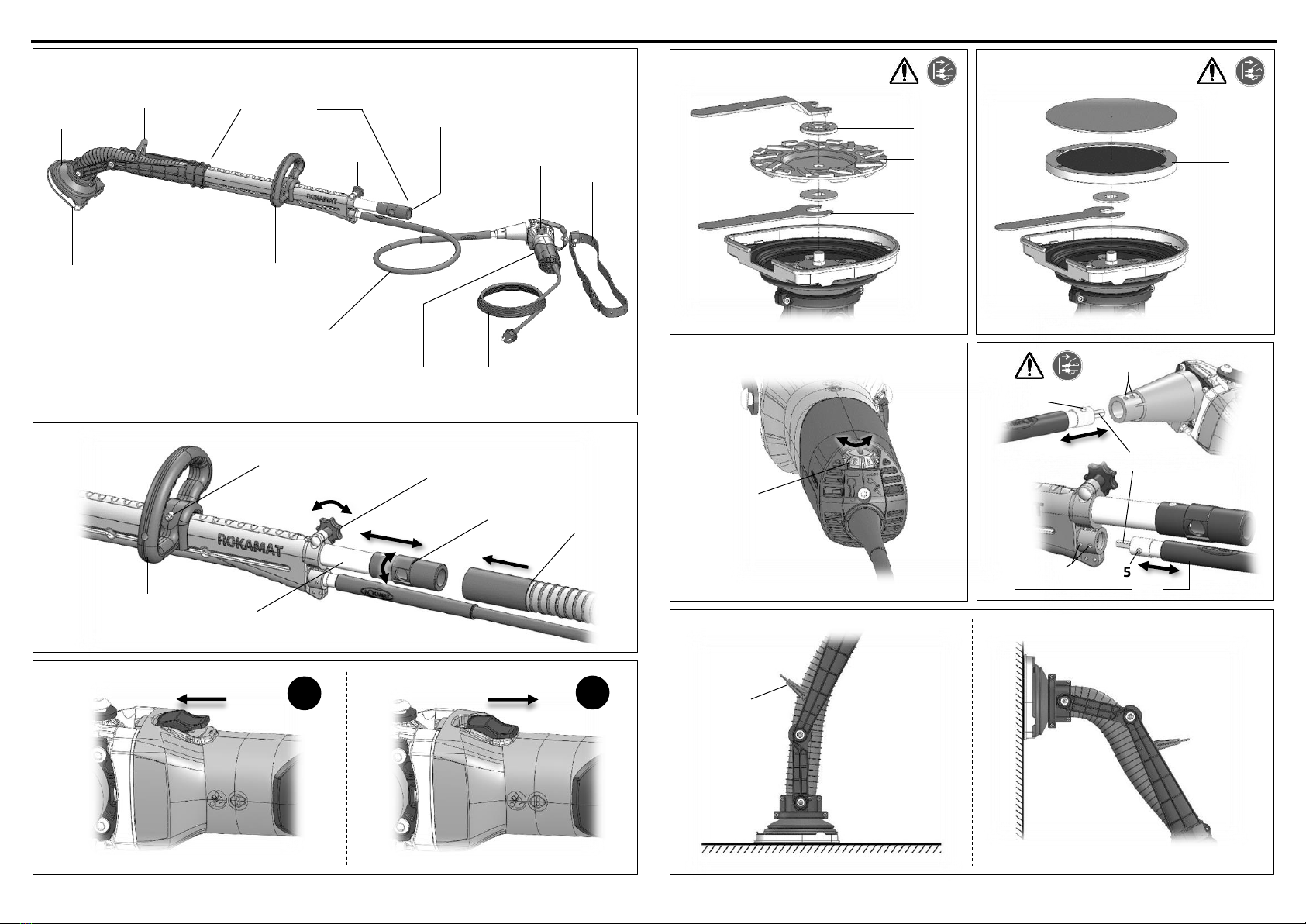
The hand-guided long-neck grinder Gex is intended
for the grinding and polishing of ceilings, walls and
floors, indoors and outdoors. It is suitable for con-
crete and stone grinding, for removing concrete
burrs, coatings, loose render as well as paint and
adhesive residue, for levelling, roughening of
screed and evening out butt joints. It may only be
used for dry grinding. For grinding work, the unit
may only be operated in combination with a suita-
ble vacuum cleaner. The Gex is only intended for
use with ROKAMAT metal and fibre discs.
Only sufficiently qualified and trained personnel is
allowed to work with the grinder.
The intended use includes the observance of the
operating instructions, in particular the safety in-
structions and the observance of generally recog-
nized accident prevention regulations.
Grinder and polisher Gex Item No. 85000
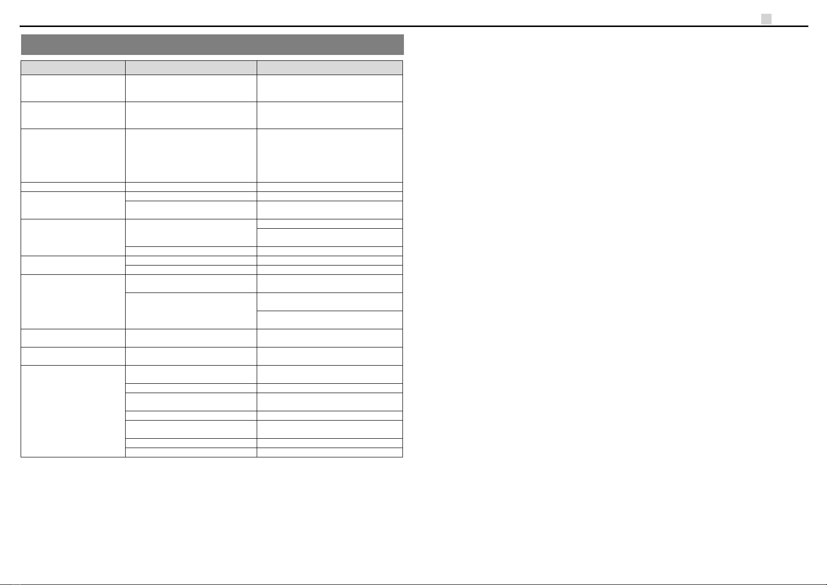
4. Technical Specifications