5INT72IQ B 16/10/05 16:24 Page 2
Black
© Rokonet Electronics Ltd. 5INT72IQ B
8/05
ON
OFF
*
34mm
63mm63mm63mm63mm
34mm 34mm 34mm 34mm 34mm
1. DESCRIZIONE GENERALE
RWT72M868IQA/RWT71M433IQA è un trasmettitore universale
con supervisione che può essere connesso ai contatti magnetici
(per protezione di finestre o porte) o ad altri sensori ed include
anche un magnete che funziona tramite un “reed” integrato nell’unità.
RWT72M868IQA/RWT71M433IQA è compatibile con i ricevitori
programmabili Rokonet ed è alimentato con una batteria standard
al litio da 3 V. Questo dispositivo è coperto da Certificazione IMQ
- SISTEMI DI SICUREZZA 2°Livello di prestazione.
CARATTERISTICHE DI
RWT72M868IQA/RWT71M433IQA
●Ha una portata radio di 300 metri in campo aperto
●Utilizza un indirizzo univoco selezionato
automaticamente tra più di 16 milioni di indirizzi
(nessun banco di microinterruttori)
●Tecnologia a microprocessore
●Batteria a lunga durata
●Completamente supervisionato
6. PROCEDURA DI MEMORIZZAZIONE DEL
TRASMETTITORE NELLA MEMORIA DEL RICEVITORE
RWT72M868IQA/RWT71M433IQAdeve identificarsi al suo ricevitore
scrivendo il suo Codice di indirizzo univoco nella memoria del
ricevitore.
Procedere come segue:
a. Impostare il ricevitore in modo memorizzazione
trasmettitori (Modo WRITE)
b. Rimuovere la batteria dal materiale isolante (Fig. 2). Premere i
due tamper del trasmettitore per circa 3 secondi per inviare un
messaggio di Indirizzo (Write). Verificate che
RWT72M868IQA/RWT71M433IQA sia stato identificato dal
ricevitore.
c. Impostare ora il ricevitore nel modo normale di
funzionamento.
Nota:
Se in caso fosse necessario rinviare un messaggio "Write",
premere ancora il tamper per circa 3 secondi, sia quello
antirimozione che quello antiapertura.
7. SCELTA DELLA POSIZIONE DI INSTALLAZIONE
a. Scegliere una posizione ottimale per garantire una buona
comunicazione radio, in prossimità dell’eventuale rivelatore o
contatto che andrà cablato al trasmettitore tramite il suo ingresso
esterno (se richiesto). Installate il dispositivo il più in alto possibile.
b. Fissare temporaneamente il dispositivo con del biadesivo.
c. Generare un segnale di allarme (aprendo o chiudendo il contatto
del RWT72M868IQA/RWT71M433IQA) e verificare che il
ricevitore abbia ricevuto il segnale. Se il segnale non è stato
ricevuto, riposizionare il trasmettitore
RWT72M868IQA/RWT71M433IQA e riprovare.
8. MONTAGGIO FINALE
Separare la parte posteriore del trasmettitore (Fig. 3), fissare il
supporto alla parete o all’infisso e infine rimontare il trasmettitore
alla base (Fig. 4).
Terminare l’installazione collegando il contatto o sensore all’ingresso
esterno dell'unità e/ o posizionare il magnete fornito con l’unità.
Nota:
Il marchio sulla plastica del contatto magnetico deve essere
posizionato dal lato opposto rispetto al marchio posto sul
contenitore del trasmettitore (Fig. 5).
Per il corretto funzionamento del tamper antirimozione
installare una vite a testa piatta nel muro in corrispondenza
della molla di chiusura del tamper antirimozione.
Per installazioni su legno e alluminio la distanza massima
di funzionamento del magnete è 10mm, per installazioni
sul metallo la distanza è di 5mm.
SPECIFICHE TECNICHE
ELETRICHE
Modello Batteria: CR123 3V al Litio
Assorbimento in Corrente: 10µA a riposo
Frequenza: 433.92 / 868.65 MHz
Blocco Trasmissioni: 2.5 minuti (se abilitato)
Trasmissione Supervisione: Ogni 15 o 65 minuti (programmabile)
Tipo di Modulazione: ASK
Autonomia Batteria: 5 anni (
Blocco trasmissioni abilitato)
FISICHE
Dimensioni: 81 x 35 x 32 mm
AMBIENTALI Immunità RF: 20V/m 80MHz a 1GHz
Temp. di funzionamento: da 0°C a 50°C
Temp. di Stoccaggio: da -20°C a 60°C
Le informazioni e le caratteristiche tecniche riportate in questo
documento sono soggette a variazione senza l'obblico di preavviso.
Per qualsiasi informazione contattare il proprio distributore.
●Tempo di risposta selezionabile come:
➤Veloce: per sensori inerziali
➤Lenta: per contatti magnetici
●Ingresso esterno programmabile per contatti N. C. o N. O. o
doppio bilanciamento resistivo
●Protezione antirimozione e antiapertura
2. MODI DI FUNZIONAMENTO
NORMALE: Il Nova 72 trasmette un MESSAGGIO di ALLARME
quando attivato e trasmette un MESSAGGIO di RIPRISTINO quando
viene ripristinato. Solamente un MESSAGGIO di ALLARME viene
trasmesso nell’arco di tempo di 2.5 minuti (con la funzione Blocco
Trasmissioni abilitata).
Nota:
Ulteriori messaggi di ripristino possono essere attivati
aprendo e richiudendo gli ingressi del trasmettitore.
WRITE: Un messaggio “WRITE” di trasmissione indirizzo verrà
trasmesso se il tasto del Tamper (sia apertura che rimozione) viene
premuto per almeno 3 secondi.
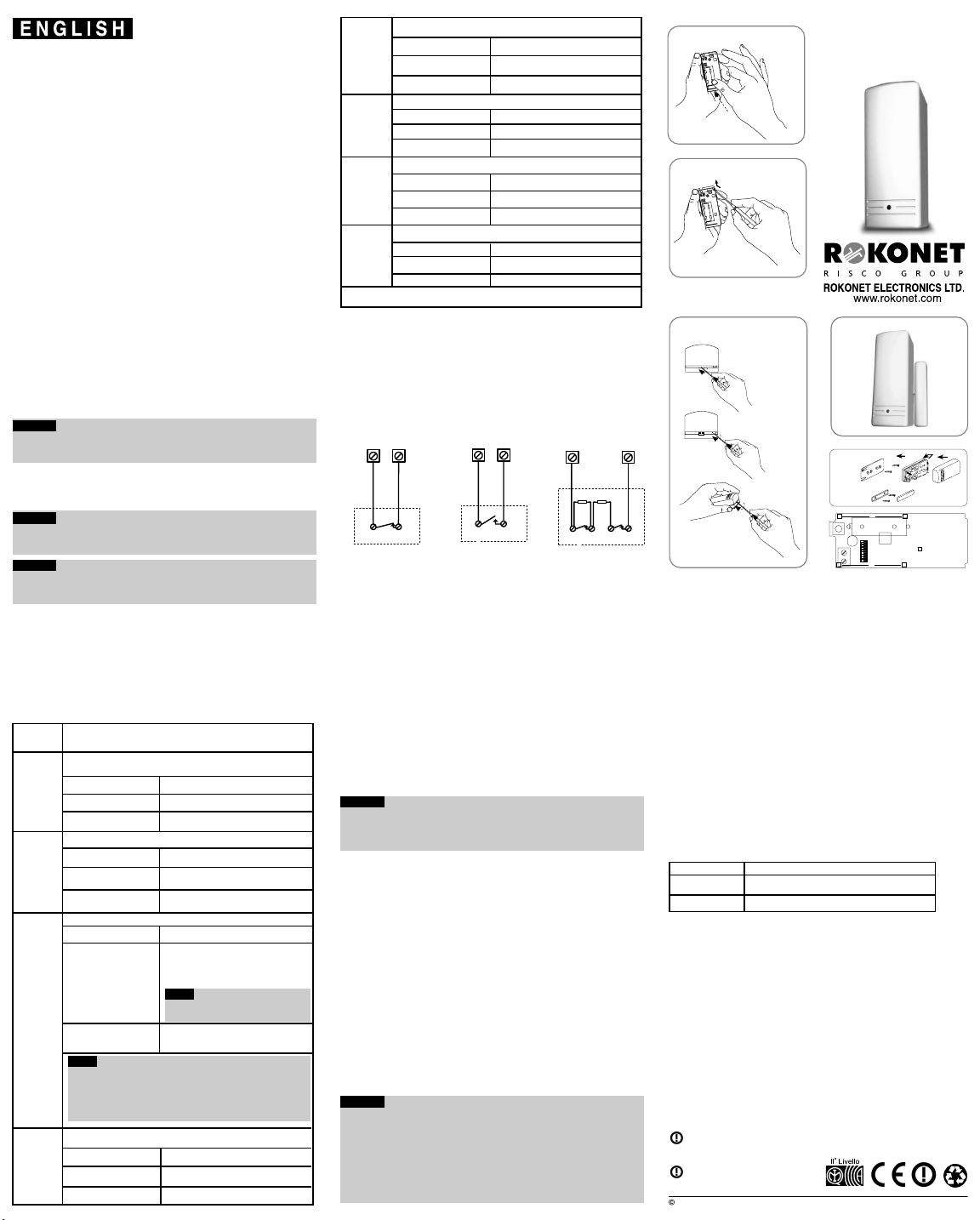
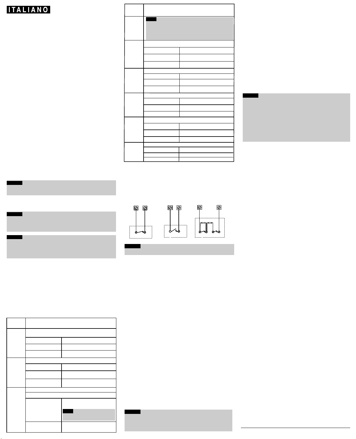
4. COLLEGAMENTO DELL'INGRESSO ESTERNO
Usare gli schemi che seguono per il collegamento del dispositivo
esterno all'ingresso del trasmettitore.
Per il collegamento DEOLin doppio bilanciamento resistivo collegare
due resistenze da 470K Ohm (fornite) come di seguito illustrato.
Nota:
per la certificazione IMQ - SISTEMI DI SICUREZZA
1. La configurazione Risposta veloce con tempo di apertura a 10
ms. è applicabile solo ai rivelatori inerziali.
2. L'utilizzo dell'ingresso esterno del trasmettitore è subordinato alla
configurazione DEOL con doppio bilanciamento resistivo. L'ingresso
esterno utilizzato in configurazione Normalmente Aperto o
Normalmente Chiuso fanno decadere la certificazione IMQ -
Sistemi di Sicurezza.
3. L'ingresso esterno va utilizzato collegando un dispositivo che
certificato IMQ - SISTEMI DI SICUREZZAal 2°livello di prestazione,
pena il decadimento della certificazione IMQ.
4. La funzione di sabotaggio Contatto Reed interno deve essere
abilitato o la certificazione IMQ - SISTEMI DI SICUREZZAdecade
dal 2°al 1°Livello di prestazione.
5. RIMOZIONE DEL CONTENITORE (Fig. 1)
Nota:
Il dispositivo invia un messaggio di supervisione ogni 15/65
minuti, per indicare lo stato degli ingressi e la condizione
della batteria.
Nota:
All’installazione dell’unità o alla sostituzione della batteria
effettuare sempre un test di comunicazione radio con il
ricevitore al fine di verificare il buon funzionamento del
trasmettitore.
INDICATORE LED:
Dopo ogni variazione dell’ingresso del trasmettitore, il LED si accende
momentaneamente. Se la batteria è scarica, il LED lampeggerà per
3 volte durante ogni trasmissione.
3. PREDISPOSIZIONE DEI MICROINTERRUTTORI
Il trasmettitore RWT72M868IQA/RWT71M433IQA è dotato di un
banco di 8 microinterruttori che predispongono il tramettitore nei
diversi modi di funzionamento di seguito riportati.
4
N. Micro-
interrut.
Descrizione
Note:
In entrambe le modalità di blocco trasmissioni:
1. Scollegando il dispositivo collegato all'ingresso l'unità trasmetterà un
allarme dopo 400 ms.
2. Aprendo nuovamente e richiudendo l'ingresso l'unità
trasmetterà un ulteriore segnale di ripristino.
5
ON
ogni 15 minuti
OFF
*
Posizione Microint. Supervisione 15/65 Minuti
Imposta il tempo che intercorre tra le segnalazioni di supervisione.
ogni 65 minuti
ON
*
DEOLAbilitato
OFF
Posizione Microint. Doppio Bilanciamento DEOL
Configura l'ingresso esterno con o senza doppio bilanciamento EOL.
DEOL Disabilitato
6
7
ON
Posizione Microint. Contatto Reed interno (S2)
OFF
*
Disabilitato
Abilitato
Posizione Microint. Reed Sabotaggio interno (S1)
OFF
Disabilitato
Abilitato
ON
*
8
Attiva o Esclude il Contatto Reed interno all'unità
Attiva o Esclude il controllo sabotaggio sul Contatto Reed interno.
*
= Configurazione di Default
Posizione Microint.
OFF
*
ON
Blocco Trasmissioni
3
Posizione Microint. Tempo di Apertura Ingresso
2
Posizione Microint.
OFF
*
ON
Modalità ingresso Esterno
1
Normalmente Chiuso (NC)
Normalmente Aperto (NO)
N. Micro-
interrut.
Descrizione
Utilizzato per configurare l'ingresso esterno NC o NO.
Imposta il tempo di apertura dell'ingresso esterno.
Normale: 400 ms (Per il controllo
di contatti magnetici, etc..)
Veloce: 10 ms (Per il controllo
di sensori sismici)
Modifica lo stato della funzione Blocco Trasmissioni.
Blocco Attivo: Dopo una trasmissione l'unità si
inibisce per 2.5 minuti. (I ripristini verranno
comunque sempre trasmessi).
Nota:
Solo un messaggio di allarme viene
trasmesso ogni 2.5 minuti.
Blocco Disattivato: Non viene applicato alcun
blocco alle trasmissioni. L'unità trasmette
sempre ogni qualvolta viene attivata.
ROKONET LIMITED WARRANTY
Rokonet Electronics, Ltd. and its subsidiaries and affiliates ("Seller") warrants its products to be
free from defects in materials and workmanship under normal use for 12 months from the date
of production. Because Seller does not install or connect the product and because the product
may be used in conjunction with products not manufactured by the Seller, Seller can not guarantee
the performance of the security system which uses this product. Sellers obligation and liability
under this warranty is expressly limited to repairing and replacing, at Sellers option, within a
reasonable time after the date of delivery, any product not meeting the specifications. Seller
makes no other warranty, expressed or implied, and makes no warranty of merchantability or of
fitness for any particular purpose. In no case shall seller be liable for any consequential or
incidental damages for breach of this or any other warranty, expressed or implied, or upon any
other basis of liability whatsoever. Sellers obligation under this warranty shall not include any
transportation charges or costs of installation or any liability for direct, indirect, or consequential
damages or delay.
Seller does not represent that its product may not be compromised or circumvented; that the
product will prevent any personal; injury or property loss by burglary, robbery, fire or otherwise;
or that the product will in all cases provide adequate warning or protection. Buyer understands
that a properly installed and maintained alarm may only reduce the risk of burglary, robbery or
fire without warning, but is not insurance or a guaranty that such will not occur or that there will
be no personal injury or property loss as a result. Consequently seller shall have no liability for
any personal injury, property damage or loss based on a claim that the product fails to give
warning. However, if seller is held liable, whether directly or indirectly, for any loss or damage
arising from under this limited warranty or otherwise, regardless of cause or origin, sellers
maximum liability shall not in any case exceed the purchase price of the product, which shall be
complete and exclusive remedy against seller. No employee or representative of Seller is
authorized to change this warranty in any way or grant any other warranty.
WARNING: This product should be tested at least once a week.
Posizione Microint.
Usato per determinare la potenza RF del trasmettitore.
Potenza RF
Potenza RF alta
Potenza RF bassa
470K
TAMPER
470K
COLLEGAMENTO INGRESSO
IN DOPPIO BILANCIAMENTO
Morsettiera Trasmettitore
RIVELATORE
ALLARME
Morsettiera Trasmettitore
COLLEGAMENTO INGRESSO
NORMALMENTE APERTO
RIVELATORE
ALLARME
COLLEGAMENTO INGRESSO
NORMALMENTE CHIUSO
ALLARME
RIVELATORE
Morsettiera Trasmettitore
OFF
ON
*