IBExU: pending drf7612a0600h_04 2/3
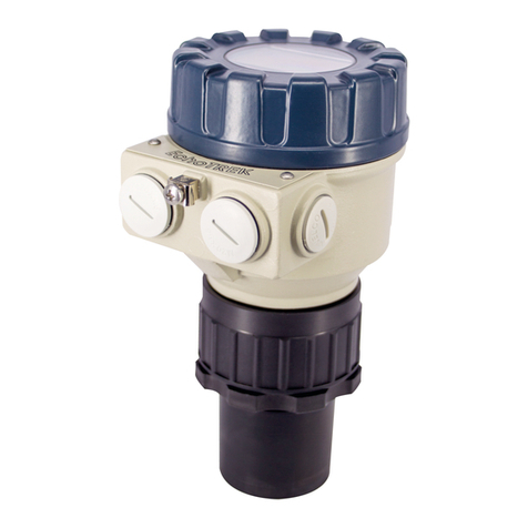
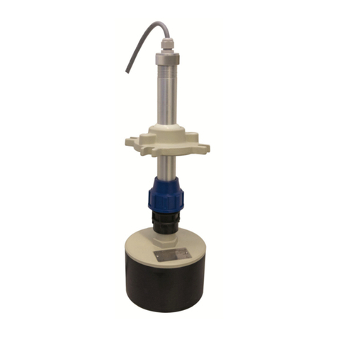
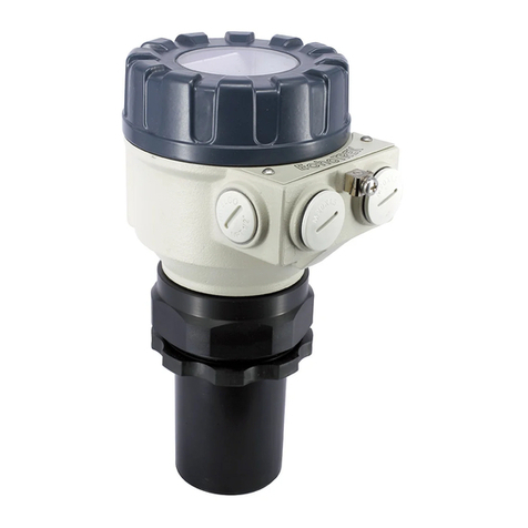
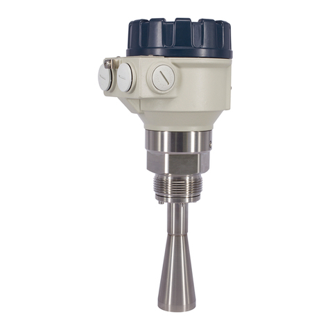
2.3 DIMENSIONS
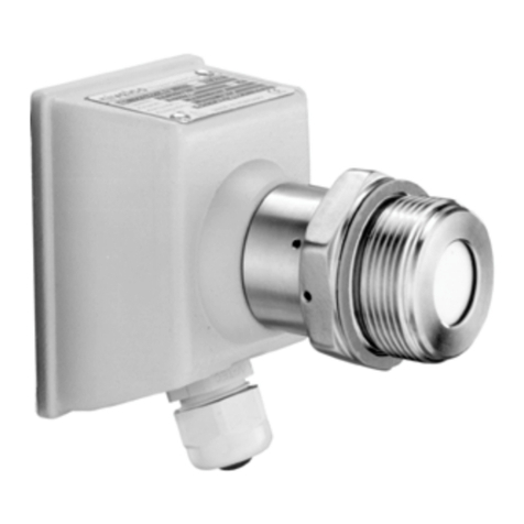
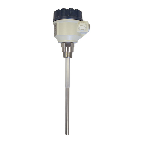
DRF-7
-
1½" BSP (DIN 3852)
stainless steel
1½" BSP (DIN 3852)
PVDF
3. SPECIAL CONDITIONS OF SAFE USE
Before turning on the device, make sure the installation is complete, and there
are no visible defects. The device may only be used within the limitations
specified in the technical specifications.
Protection against electrostatic charge:
The devices may partially contain static charging capable plastic components.
The presence of electrostatic charges may cause a risk of spark generation
and ignition and therefore electrostatic charges must be completely prevented:
-Use a shielded cable!
-Avoid friction on plastic surfaces!
-Do not clean the device dry! For example, use a wet duster!
Ex ia certified transmitters may only be operated in qualified, certified and
approved galvanically isolated intrinsically safe Ex ia circuits complying with the
technical data and the device’s explosion protection marking. The metal
housing of the device must be connected to the EP (equipotential) network!
4. INSTALLATION
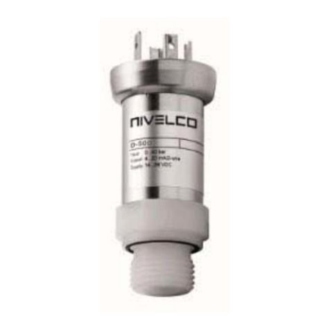
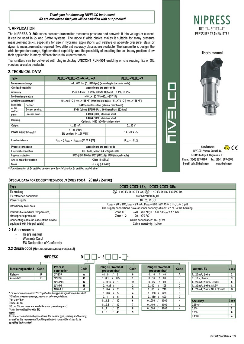
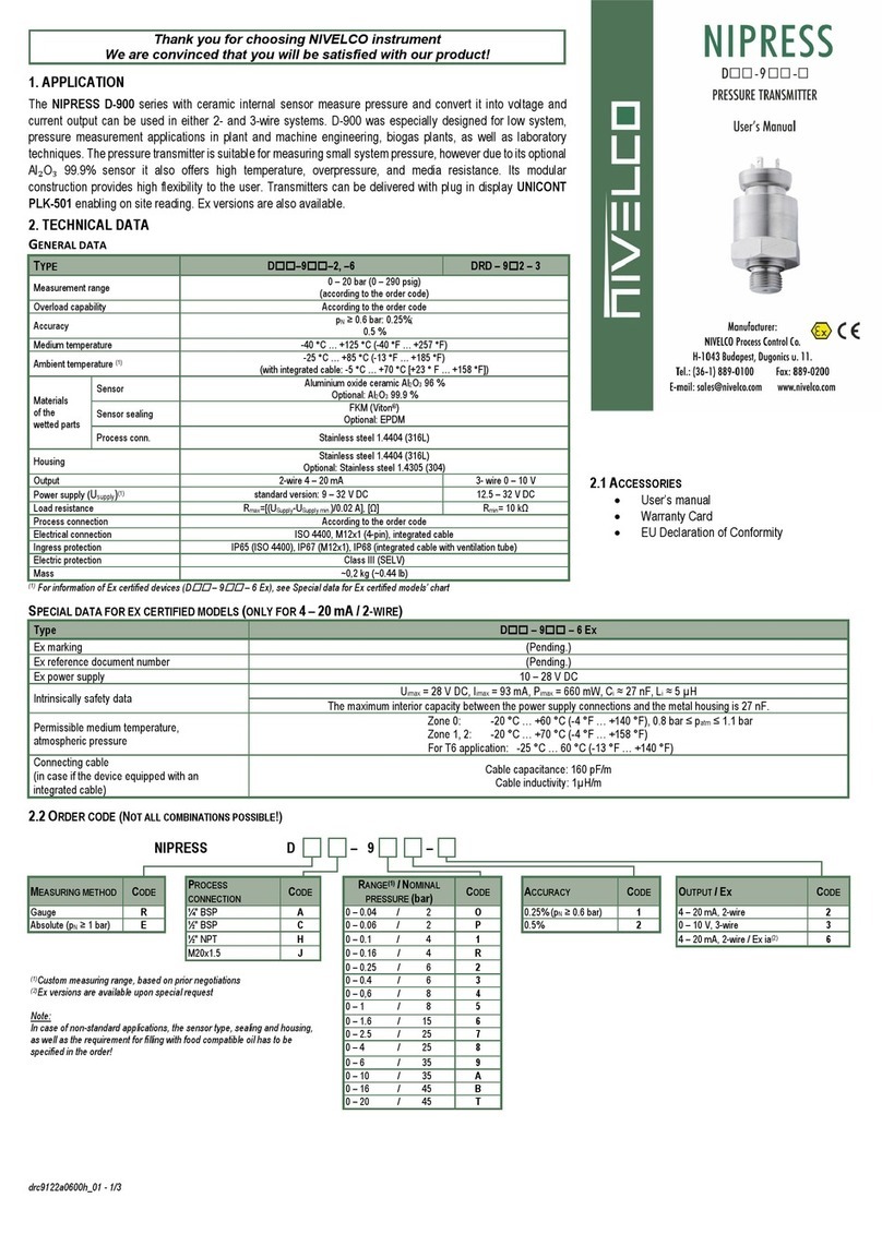
Due to its small size and weight NIPRESS D-700 can be directly installed on
tanks, pipes, machines, etc. without mounting fittings.
In case of level measurement, the unit should be thread in a stub at the bottom
of the tank or the tank wall possibly near to the bottom.
To provide a chance for replacement of the instrument during operation the use
of closing armature is recommended. A simple ball valve will be suitable for
lower pressure, but for higher pressure (above 6 bar) a three-way blow-off
needle-valve is suggested. For medium with temperature over 75 °C (167 °F),
application of condensing device would protect the instrument against
overheating and extends its lifetime.
The temperature of the condensation in the condensing devices (in the water
lodge) is only 10 °C … 20 °C (18 °F … 36 °F) higher than the ambient
temperature.
Using a longer impulse tube, its proper sloping for the necessary de-aerating
and emptying has to be ensured.
Measuring low pressure values in systems with substantial height difference
between the transmitter and place of measurement the hydrostatic pressure of
the medium in the impulse pipe should be taken into consideration.
In the case of outside installation, the unit is supposed to be protected against
rain or splash water, because malfunction may occur if the connector’s screw is
not tightened properly (i.e. not appropriate sealing).
Installation position: any.
4.1 INSTALLATION INSTRUCTION
Depending on the measured medium, it may cause a hazard to the installer,
therefore the wear of suitable protective clothing, gloves, and goggles are
recommended.
Torque transmission is only allowed to be applied on the hexagonal screw on
the instrument body (torque wrench).
Be careful because the membrane is very vulnerable!
The cylindrical housing of the transmitter must not be gripped and
tightened with a pipe wrench!
The plug-in electric connector (ISO 4400) can be unplugged after releasing and
removing its fastening screw. The connection insert can be pushed out by a
screw driver from the direction of the screw.
Pushing the electric cable through the cable gland it can be connected to the
relevant points of the connector. Make sure that the cable gland and the
sealing plate of the connector are tightened properly!
Tighten the screw of the connector so that the sealing plate underneath seals
properly!
Install the device only in a pressure and current free state!
Choose an installation position to allow the splashed liquid to drain off from the
device!
Avoid the mechanical tensioning of the device during installation,
especially if the pressure connector is made of PVDF!
For the sake of noise suppression, the transmitter housing is grounded. If the
grounding of the process is correct no further grounding is needed, otherwise
the instrument should be grounded.
Installation steps:
The specified tightening torques must not be exceeded!
Tightening torques in case of stainless steel process connection:
1½" BSP: max. 25 Nm.
Mounting steps for BSP thread connections according to DIN 3852
Do not use any additional sealing material such as Teflon tape!
Check if the O-ring is undamaged, it has a flawless and clean surface and
seated in the designated groove.
Screw the device into the corresponding thread by hand, and tighten the parts
with a suitable torque wrench. If your device can be secured with a knurled
ring, the pressure transmitter should only be tightened by hand!
5. WIRING
Shielded and twisted multicore cable is recommended for the electrical
connection.
For devices with cable gland, make sure that the external diameter of the used
cable is within the allowed clamping range! Once connected the wires, tighten
the gland screw firmly until proper sealing!
For the installation of a device with an integral cable, the bending radiuses
have to comply with the following:
Cable without ventilation tube:
-static installation: 5-fold cable diameter
-dynamic application: 10-fold cable diameter
Cable with ventilation tube:
-static installation: 10-fold cable diameter
-dynamic application: 20-fold cable diameter.
2-WIRE CURRENT OUTPUT
3-WIRE VOLTAGE OUTPUT
