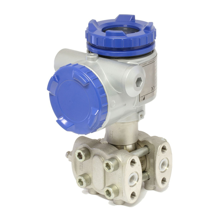
Fuji Electric FCX-AII Series Operating instructions

Fuji Electric France S.A.S.
INSTRUCTIONS MANUAL and
SERVICE INSTRUCTIONS
"FCX-AII" Series transmitters
Types : Differential pressure : FKC
Gauge pressure : FKG
Absolute pressure : FKA
Level transmitter : FKE
With remote seal(s) : FKD, FKB, FKM
Date Septembre, 2018
INF-TN4 FCXA2g-E

2

3
CAUTION :
Rotating the upper assembly part :
The upper assembly (housing and electronic unit) can not be rotated by 90° left or right just by
removing the 2 hexagonal socket bolts (M6 x 12)
If the assembly parts must be turned over than 90°, or if
the position is already amended since the delevery by Fuji,
it's necessary to remove the electronic unit from the
housing and disconnect the flat-cable from the electronic
measuring cell before turn the housing.
If necessary, amend the flatcable's position connecting
electronic unit and measuring cell, after fit the different
parts.
Failure to observe this may lead to the deterioration of the
flat cable, which is not covered by the manufacturer's
warranty.

4
Our pressure transmitters have been designed to meet international standards and regulations.
It is necessary to read carefully the manual before use these transmitters, to familiarize yourself
with the installation, wiring processes, wiring and all operations and maintenance.
The technical information is detailed in each "Technical Specification" for each version of the
transmitters.
Carefully read the instructions ATEX "HD FCXAII 002" for any use of sensors in dangerous
areas.
The instrument nameplate as shown below is attached at the transmission unit of this transmitter.
Before use, make sure the contents of the nameplate agree exactly with your specifications.
1
2
3
4
5
6
7
8
9
10
11
12
Tag number
Model
Transmitter type (see corresponding "technical datasheet")
Range
Power supply
Output
Span limit
MWP
Serial number
Manufacturing date
Hazardous locations description
2014/68/EU G1 TAMB. MIN. -40°C/ MAX. +85°C WITHOUT OPTIONS.
For equipments specified category III or IV, G1 = for use with all kinds of fluid G1 = for use with
all kinds of fluid
INTRODUCTION

5
EMC Directive (2014/30/EU)
All models of FCX series electronic pressure transmitters type FCX-AII & CII are in accordance with :
• The harmonized standard EN 61326-1 : 2013 (Electrical equipment for measurement, control and laboratory use -
EMC requirements - Part 1: General requirments).
Emission limits : EN 61326-1 : 2013
Frequency range (MHz) Limits Basic standard
30 to 230 40 dB (V/m) quasi peack, measured at 10m distance EN 55011 / CISPR 11
Group 1 Class A
230 to 1000 47 dB (V/m) quasi peack, measured at 10m distance
Minimum requirements for Immunity tests : EN 61326-1 : 2013 (Table 2)
Phenomenon Test value Basic standard Performance criteria
Electrostatic discharge (EDS) 4 kV (Contact) EN/IEC 61000-4-2 B
8 kV (Air)
Electromagnetic field EN/IEC 61000-4-3 A
10 V/m (80 to 1000 MHz)
3 V/m (1.4 to 2.0 GHz) 1
V/m (2.0 to 2.7 GHz)
Rated power frequency 30 A/m (50 Hz, 60 Hz) EN/IEC 61000-4-8 A
Magnetic field
Burst 2 kV (5/50 ns, 5 kHz EN/IEC 61000-4-4 B
Surge EN/IEC 61000-4-5 B
1 kV - Line to line
2 kV - Line to ground
Conducted RF disturbances 3 Vrms (150 kHz -80 MHz) EN/IEC 61000-4-6 A
Performance criteria (A & B) :According EN 61326-1 : 2013
EMC DIRECTIVE

6
First of all, read carrefully the “Safety instructions” for your own safety and for correct use of
the transmitter.
• The risks related to a non-respect of the instructions are priorized as follow :
Risk of death or sever injury if the safety instructions are not fol-
lowed.
In case of wrong handling probable injury or physical damage can
happen.
Important instructions to be respected.
General observations concerning the product, product handling and
correct use of the transmitter.
CLASSIFICATION OF SAFETY INSTRUCTIONS
DANGER
INDICATION
ATTENTION
PRECAUTION

7
Storage for a long period
For installation, select an appropriate place
At a place allowing an adequate space for check-up
Mounting position
Attention to overload
Others
Store the transmitter in a dry room at normal
temperature and humidity.
Keep protection caps in place at the conduit
connection and process connection.
Site at location with minimal vibration, dust and
corrosive gas
Site at location large enough to allow mainte-
nance and checking.
Mount to a pipe horizontally or vertically.
Do not apply a pressure outside the specified
range.
Besides the above, be sure to observe the
cautions given in this manual.
IMPORTANT RECOMMENDATIONS

8
Introduction........................................................................................................................................................................................................................................................................................................................................................ 4
CEM Compatibility....................................................................................................................................................................................................................................................................................................................... 5
Classification of safety instructions................................................................................................................................................................................................................................ 6
Important recommendations..................................................................................................................................................................................................................................................................... 7
1. Outline...................................................................................................................................................................................................................................................................................................................................................................... 9
2. Operating parts and their functions...................................................................................................................................................................................................................... 10
3. Start up and shutdown...................................................................................................................................................................................................................................................................................... 12
3.1 Preparation for Start up ................................................................................................................................................................................................................................................... 12
3.2 Operation .................................................................................................................................................................................................................................................................................................................... 13
3.3 Shutdown ................................................................................................................................................................................................................................................................................................................... 14
4. Adjustment................................................................................................................................................................................................................................................................................................................................................ 16
4.1 Adjustment with FXW (HHC) ........................................................................................................................................................................................................................ 16
4.2 Zero adjustment by the screw on the transmitter............................................................................................................................... 36
4.3 Span adjustment by the screw on the transmitter............................................................................................................................ 37
4.4 Local adjustment with LCD display .............................................................................................................................................................................................. 38
5. Maintenance......................................................................................................................................................................................................................................................................................................................................... 41
5.1 Periodic inspection......................................................................................................................................................................................................................................................................... 41
5.2 Troubleshooting....................................................................................................................................................................................................................................................................................... 42
5.3 Replacement of defective parts............................................................................................................................................................................................................... 43
5.4 Adjustment after replacement of amplifier or measuring cell .......................................................................... 50
6. Installation and piping........................................................................................................................................................................................................................................................................................ 51
6.1 Installation................................................................................................................................................................................................................................................................................................................ 51
6.2 Piping ..................................................................................................................................................................................................................................................................................................................................... 65
7. Wiring......................................................................................................................................................................................................................................................................................................................................................................... 70
7.1 Wiring procedure ................................................................................................................................................................................................................................................................................. 71
7.2 Power voltage and load resitance.................................................................................................................................................................................................... 72
7.3 Grounding ................................................................................................................................................................................................................................................................................................................. 73
Annexes:
A1. Built-in arrestor.................................................................................................................................................................................................................................................................................................................. 74
A2. Calibration.......................................................................................................................................................................................................................................................................................................................................... 76
A3. Parameter setting prior to delevery................................................................................................................................................................................................................ 78
A4. Spare parts....................................................................................................................................................................................................................................................................................................................................... 79
CONTENTS

9
EEPROM
Sensor
parameters
Analog to
Digital
Converter
Digital to Analog
Converter
Micro Processor
• Signal conditioning
• Reranging
• Diagnostics
• Communication
EEPROM
Transmitters
Parameters Communication
FUJI/HART®
Manual
Zero/Span
Adjustment
25.0
8.00 kPa
FXW
0Y
1
4
789
65
23
MNO
S
RQ
UV
W
Z
.
[
HHC
Hand held Communicator
{
HPLP
Control
system
Analog indicator
(option)
4-20 mA signal
LCD digital indicator
(option)
Micro
Capacitance
Silicon Sensor
Sensor Unit Electronics Unit
1
The FCX-AII series transmitter accurately measures the differential pressure, level liquid, gauge
pressure or flow rate, and transmits a proportional current signal of 4 to 20mA DC.
All the adjustment functions are incorporated in the transmission unit for making adjustments
easily and exactly.
Transmitter settings (such as range and damping time constant, etc.) can be changed from an
FXW communicator (Hand Held Communicator).
The transmitter utilizes a unique micromachined capacitive silicon sensor with state-of-the-art
microprocessor technology to provide exceptional performance and functionnality.
The transmitter is compact and light, provide high accuracy and reliability.
Local adjustment of zero and span are possible from outside screw on the electronic housing.
Measuring principle
The operating principle of the FCX-AII series transmitter is shown in the block diagram below.
The input pressure is changed into an electrostatic capacitance in the detecting unit.
The change proportional to the pressure undergoes conditioning and amplification in the trans-
mission unit, and is then output as a current of 4 to 20mA DC
OUTLINE

10
Terminals
OPERATING PARTS AND THEIR FUNCTIONS
Description of FCX-AII series transmitters
Transmission Unit
Part name Description
Detecting unit Detects pressure, differential pressure or level of fluid.
Transmission unit Converts the detected signal into an output signal.
Vent/drain plug Used for gas discharge or draining.(Be carreful should be paid under a high pressure.)
Process connection Connects impulse pipes from the process.
Conduit connection Connects the output cable.
Zero adjustment screw Adjusts zero (Refer to Section 7.)
Part name Description
Analog indicator connector Used for connecting an analog indicator.
Digital indicator connector Used for connecting a digital indicator.
Indicator (option) Analog or digital indicator, available.
Symbol Description
+, – Connects the output cable..
CK+, CK– Used for checking the output or connecting an indicator..
An external terminal used for grounding.
Vent/Drain
Plug
Zero/Span
adjustment
Detecting Unit
Transmitter
Unit
Process Connexion
Analog indicator
connector
Digital indicator
connector
Transmission Unit
(Digital) (Analog)
Indicator
%
0
20
40
60
80
100
Terminal Unit
CK+
CK–
+
–
FIX
OUT
DISP
ZERO
abs
%
2

11
FIX
OUT
DISP
ZERO
abs
%
Mode indication
Mode
%
ZERO
DISP
OUT
FIX
abs
–
N
When indicated When not indicated
% output Actual scale
External zero adjustment possible External zero adjustment impossible
Digital indicato display Digital indicator proportional display
output Proportional output
Fixed current mode Measurement mode
Sampling status (Flicker)
Absolute pressure Gauge pressure
Output value < Zero Output value Zero
(a part of unit indicator)

12
After adjustment of the transmitter, it should be kept energized for about 10
seconds to write the adjustment results into memory.
The zero point check or zero adjustment in flameproof area, is only possible by the outside screw
on the electronics housing without opening the covers of this housing and in case of adjustment
via HHC, the local wiring (connection) is not allowed.
Turn on the power to the transmitter.
Check the output signal of the transmitter by connecting a DC ammeter across CK+ and CK– of
the terminal block.
After ten minutes or longer, adjust the transmitter output current at 4 mA (zero adjustment).
(See below)
START UP AND SHUTDOWN
3
3.1 Installation :
After installation (refer to chapter 6.1) and before start up of the transmitter, be sure to perform
the following checks and procedures.
Preparation :
(1) Check for liquid or gas leakage of the process connection by ap-
plying soapy water or similare.
(2) Check of the electrical connection according to the “Terminal block
connection diagram” shown in chapter 7.1.
(3) Vent the process covers of the transmitter.
Before starting up the transmitter in flameproof area, please read carre fully
the technical instruction note ATEX Ref.HD FCX AII 002 .
The compatibility of process with the transmitter, has to be checked and ensured by skilled
people from customer side.
(4) Perform zero point adjustment.
Zero point check
Zero adjustment :
Adjustment by zero adjustment screw
Zero adjustment is possible from outside screw on electronic hou-
sing.
Adjust zero point of the transmitter to 4 mA by turning the zero ad-
justment screw.
The higher you turn the screw, the quicker is the change of the
zero.
After all operations are finished, assemble and tight the covers of the electronics housing.
(Tightening torque: 20 N.m).
When the plant requires chemical cleaning at the start up operation, be
sure to close the isolating valves of the transmitter to avoid that cleaning
liquid or particules are introduced to the transmitter wetted parts.
Decrease
Increase
Fine adjustment : turning slowly
Rough adjustment : turning quickely
INDICATION
DANGER
ATTENTION

13
3.2 Operation
(1) Operation of gauge and pressure transmitter :
Open the valve slowly to apply a
pressure.
When a pressure is applied, the trans-
mitter is set inthe operating status.
(2) Operation of differential pressure transmitter :
Set the operating status by manipulating the manifold valve.
Open
Open
Stop valve on the
LP side
Stop valve on the
HP side
Equalizing
valve
Close
Make sure the equalizing valve is open
Open the stop valve on the HP side
slowly.
Close the equalizing valve.
Open

14
Finally, open the stop valve on the LP
side slowly
Use a field indicator, receiving instrument or HHC to check the operating status.
3.3 Shutdown
Follow the procedures
Open
Close
Close the valve slowly to stop applying a pressure.
The transmitter is set in the measurement stop status.
(1) Absolute and gauge pressure transmitters (FKG or FKA) :
Check of operating status

15
(2) Flow and differential pressure transmitter (FKC) :
Close the stop valve on the high pressure side (HP
side) slowly.
Open the equalizing valve..
Close the stop valve on the low pressure side slowly
Close
Open
Close
Before a long shutdown, discharge the process fluid and drain comple-
tely from the transmitter. This is to protect the transmitter from freezing,
corrosion, etc...
PRECAUTION

16
CK+
CK–
+
–
To junction
terminal or
instrument
room
To HHC
Instrument room
Terminal block
DC power supply
16.1 to 45V DC
Load resistor
2507or more Note)
Note) See 7.2 “Power voltage
and load resistance”.
Junction terminal Zener barrier
Field device
To operate the FCX-AII series transmitter, the FXW communicator is used for each adjustment.
4.1 Adjustment with the FXW communicator (HHC)
The span adjustment of the transmitter can be done by using the FXW communicator without
applying a reference pressure. Here after you will find the wiring of the FXW to modify the
transmitter parameters. For the use and the start up of the communicator, please refer to the
instructions of the FXW (HHC).
Remarks :
* The HHC must be on [OFF] position during the connection.
It can't be connected to the terminals CK+ and CK- of the terminal block of the transmitter.
* The HHC has no polarity. (You can connect either the red or black electrical wire to the ter-
minals +or -of the transmitter or on the wires of the loop).
HHC = Hand Held Communicator
4.1.1 Connection of HHC
The HHC can be connected in any point of the loop.
To communicate with the HHC, a load resistor of 250mini is required.
Refer the following diagram connection of the HHC.
ADJUSTMENT
4
After adjustment of the transmitter, it should be kept energized for about 10
seconds to write the adjustment results into memory.
In the case of a flameproof transmitter, the HHC can only be connected
via the junction box located outside the hazardous area.
DANGER
In the case of a flameproof transmitter, never connect the FXW to the ter-
minal block of the transmitter in hazardous area installations.
DANGER
INDICATION

17
4.1.2 Start up of the HHC
• Put on/off switch of the HHC on “ON” position.
Put on the enclosed “key” in the corresponding location of the HHC. Without the key and
with the key in vertical position, you can just read the transmitter parameters.
To write new parameters in the transmitter, the key needs to be in horizontal position.
Otherwise, you will have an inscription on the HHC screen "INHIBIT KEY OK ?" to let you
know that the key needs to be turned to enable the programming of new parameters in the
transmitter.
NOTA : "INHIBIT KEY" means that the key permits or inhibits (prohibited) writing parame-
ters in the transmitter
• The transmitter version and the revision of the HHC software are indicated on the screen during
the start up.
After around 4 seconds the inscription "PUSH MENU KEY" appears (please push menu key)
HHC with the optional printer will have the inscription "PAPER FEED". Please push on <INC>
key. By pushing on <INC> key the paper feed is activated.
"PUSH MENU KEY" will be indicated on the screen by if you push on the clear <CL> key.
On the screen appears the inscription "RECEIVING START". The HHC reads out the data from
the transmitter, and switches automatically in the first programming menu : TAG menu.
In case of a connection problem, "NO CONNECTION" will appear on the screen. The "PUSH
MENU KEY" appears again if you push the clear <CL> key.
The reasons of a communication problem can be :
- The 4-20 mA output is not powered.
- The 4-20 mA is disconnected.
- The connection between the amplifier unit and the measuring cell is wrong.
- The loop resistance value doesn't correspond to the required one depending on the power
supply.
- The HHC is not connected to the correct terminals
Configuration menus of the FXW communicator
The configuration is based on different menus. The identification of the following program
steps are indicated on the bottom line of the screen inside following signs ( < > ).
The configuration menues are selectable by pushing on the INC (increase : configuration
N+1), or the DEC (decrease : configuration N-1), keys. The most important menus can be
selected with a specific, corresponding key.
The <CHNG> (CHANGE, modification) key inside each menu gives the possibility to make
modifications or to program new parameters in the transmitter with the alphanumeric keys.
To program letters, you first need to push the <ALHA> key, each time before programming
the letter. To add a space between caracters, you have to push the keys <ALHA>, and <
>. To delete caracters, please use the clear key <CL>.
When the modification is programmed, you have to push the enter key <ENT> to send the
new information to the transmitter. For safety reasons, you need to confirm the modification
a second time by replying on the question "CHNG OK ?" . You confirm by typing a second
time on the enter < ENT> to confirm.
At this moment the new programmed information are written in the transmitter memory,
"WRITE" indication will appear on the screen of the FXW

18
The following shows the flow of 21 key operations (n° 1 to L), explained for FXW version 7.0
(FXW 1-A4).
FXW prior to Version 7.0 are not available of operation of FCX-AII series transmitter. In this case,
the user is requested to contact our office for ROM version up.
Classification Display symbol Key symbol Referential
page
1
2
3
4
5
6
7
8
9
A
B
C
D
E
F
G
H
I
TAG No.
Ty p e
Display of serial No.
Industrial value unit
Range limit
Range change
(LRV,URV)
Damping adjustment
Output mode and value
Burnout direction
Calibration of the zero/span
Calibration of output circuit
Indication of measured data
Self-diagnosis
Printer function
Lock of adjustment
functions
Indication of digital
indicator
Programmable linearization
function
Rerange
(Set LRV/URV calibration)
INC
INC
INC
INC
INC
INC
INC
INC
INC
INC
INC
INC
INC
INC
INC
INC
INC
INC
1:TAG No.
2:TYPE
3:SERIAL No.
4:UNIT
5:RANGE LIMIT
6:RANGE
7
:DAMPING
8:
OUTPUT MODE
9:BURNOUT
A:CALIBRATE
B:OUTPUT ADJ
C:DATA
D:SELF CHECK
E:PRINT
F:
XMTR EXT. SW
G:XMTR DISPLAY
H:LINEARIZE
I:RERANGE
19
19
20
20
21
21
22
23
24
25
26
27
27
28
28
29
31
33
INCINC
INC
INCDATA INC INC INC
INCINCINCDATA INC
INCDATA INC INC INC
MENU
MENU INC
MENU INC INC
UNIT
INC
UNIT
RANG
DAMP
LIN
/?
LIN
/? INC
CALB
OUT
DATA
INCDATA
INCINCDATA
INCINCINCDATA
J
Saturation current value
and specification setting
INC
J:SATURATE CUR 34
INCINC
INCDATA INC INC INC
INC
K
Write protect
INC
K:WRITE PROTCT 35
INCINC
INCDATA INC INC INC
INC INC

19
Type
Type of field device is displayed and changed
(ex. of differential pressure transmitter).
• After TAG N° is displayed, press the <INC>
key to display TYPE image.
• To make changes press the <CHNG> key
under display 1 and the cursor will be dis-
played under display 2 .
• Set the alphanumeric keys as necessary
under display 2 . To set the alphabet, press
the <CHNG ALHA> key first.
Using < > < > keys, cursor position can be
moved.
•At the completion of setting, press the <ENT>
key and a prompt is displayed check entry
under display 2 .
• If the entry is correct, press the <ENT> key to
input it to the field device under display 3 and
4 and the initial image 1 is displayed.
• To display SERIAL N°., press the <INC> key
under display 1 .
Tag Number
To set the TAG N° of each field device, use the
procedures shown in the following diagram.
TAG N° can be inputted up to 26 characters
of alphanumeric codes.
• After PUSH MENU KEY is displayed, press
the <MENU> key to display TAG N°.
• To make changes press the <CHNG> key
and the cursor will be displayed under dis-
play 1 .
• Set the alphanumeric keys as necessary
under display 2 .
To set the alphabet, press the <CHNG
ALHA> key first.
Using < >< > keys, cursor position can
be moved.
•At the completion of setting, press the <ENT>
key and a prompt is displayed check entry
under display 2 .
• If the entry is correct, press the <ENT> key
to input it to the field device under display
3 and 4 and the initial image 1 is dis-
played.
• To display TYPE display, press the <INC>
key under display 1
1: TAG No
FICRA-1234 xxxxxxxxx
xxxxxxxxxxxxxxxxxxx
< INC > < CHANGE >
1-1: TAG CHANGE
FICRA-1234 xxxxxxxxx
xxxxxxxxxxxxxxxxxxx
< ENT > < CL >
1-1: TAG CHANGE
FICRA-4321 xxxxxxxxx
xxxxxxxxxxxxxxxxxxx
CHNG OK?< ENT/CL >
1-2: TAG WRITE
FICRA-4321 xxxxxxxxx
xxxxxxxxxxxxxxxxxxx
To menu
2 : TYPE
0: PUSH MENU KEY
CL
INC
CHNG
MENU
CL
ENT
ENT
after setting
12
3
4
2: TYPE
FKCXXXXX-XXXXX
< INC > < CHANGE >
2-1: TYPE CHANGE
FKCXXXXX-XXXXX
< ENT > < CL >
2-1: TYPE CHANGE
FKCXXXXX-XXXXX
CHNG OK?< ENT/CL >
2-2: TYPE WRITE
FKCXXXXX-XXXXX
To Menu
3 : SERIAL No
Menu 1 : TAG No
CL
INC
INC
CHNG
CL
ENT
ENT
after setting
12
3
4

20
Display of SERIAL N°
SERIALN° and transmitters software version
are displayed.
• After setting TYPE, press the <INC> key to
display SERIAL N° and software version
of transmitter.
• By pressing the <INC> key, UNIT setting
image is displayed.
3: SERIAL No.
N8G07131
VERSION 1.1
< INC >
2 : TYPE
INC
INC
4 : UNIT
Industrial value Unit
26 industrial units can be used by the ope-
rator (see below).
Note:
The mark < > is settable for absolute pres-
sure transmitter only.
• When pressing <CHNG> under display
1 , the display for changing the unit of
industrial value 2 appears.
• The desired unit of industrial value is se-
lectable by using <INC> or <DEC> under
display 2 .
•Display 3 is provided for confirming your
change.
•Display 4 is for registering the unit of
industrial value.
< UNIT CHANG >
4-1: UNIT CHANGE
kPa
< INC > < ENT > < CL >
4-1: UNIT CHANGE
CHNG OK? < ENT/CL >
4-1: UNIT WRITE
< INC >
4: UNIT
To menu No5 :
RANGE LIMIT
kPa
< CHNG >
(NEXT MPa)
(NEXT MPa)
kPa
kPa
4-1: UNIT WRITE
UNIT < CL >
NOT SUITABLE
Not suitable unit display
Pa
Menu No3 :
SERIAL No
CL
CL
CL
INC
INC
CHNG
ENT
ENT
1
2
3
4
INC
DEC
INC
mmH O2
cmH O2
mH O2
g/cm
2
Pa
inH O
2
psi
ftH O
2
< Torr >
kg/cm
2
< atm >
hPa
kPa
MPa
mbar
bar
mmAq
mmHg
cmAq
mAq
mmWC
cmWC
mWC
inHg
cmHg
mHg
Table of contents
Other Fuji Electric Transmitter manuals

Fuji Electric
Fuji Electric FCX Series Quick start guide

Fuji Electric
Fuji Electric FCX-AII-VG Series User manual

Fuji Electric
Fuji Electric FCX-AII-V4 Series Operating instructions

Fuji Electric
Fuji Electric FCX-AIV Series User manual

Fuji Electric
Fuji Electric FCX-CII SERIES User manual

Fuji Electric
Fuji Electric FRC User manual

Fuji Electric
Fuji Electric FCX-AII-V5 series Operating instructions