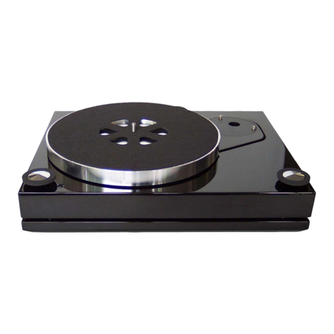
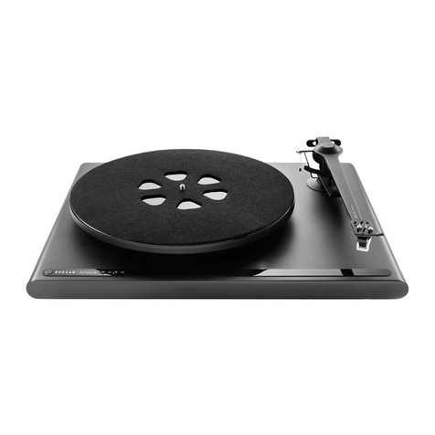
Roksan Audio TMS 3 User manual

ROKSAN AUDIO LIMITED 6 NORTHFIELD INDUSTRIAL ESTATE
BERESFORD AVENUE ALPERTON MIDDLESEX HA0 1NW ENGLAND
T
TE
EL
L.
.
+
+4
44
4
(
(0
0)
)2
20
08
8
9
90
00
0
6
68
80
01
1/
/
+
+4
44
4
(
(0
0)
)2
20
08
8
9
90
00
0
6
68
80
02
2
F
FA
AX
X.
.
+
+4
44
4
(
(0
0)
)2
20
08
8
9
90
00
0
0
07
73
34
4
w
ww
ww
w.
.r
ro
ok
ks
sa
an
n.
.c
co
o.
.u
uk
k
e
em
ma
ai
il
l
i
in
nf
fo
o@
@r
ro
ok
ks
sa
an
n.
.c
co
o.
.u
uk
k
U
Us
se
er
r
m
ma
an
nu
ua
al
l

Roksan Audio ltd TMS 3 Record Player User Manual
General Use
Version 2.00
All specifications are liable to change without notice. E&OE Page 2 of 27 ENGLISH
Congratulations on becoming a TMS Series 3 owner. Your TMS 3 is constructed to the finest specification and it
is designed to provide enjoyment and insight to recorded music on vinyl like never before. The unparalleled
precision, absolute detail, emotional and musical performance of the TMS 3 sets the standard for all record
playing systems. Correct setup and installation of the TMS 3 and its partnering equipment is essential to the
overall performance of the entire system.
Please read the contents of this manual thoroughly. It will help you to understand your TMS Series 3 better and
enhance your musical experience.
This manual is divided into the following sections:
•Introduction
•Unpacking
•Caution
•Design
•Setup Summary
•Setup Diagrams
•Installation
•Operation
•Troubleshooting
•Guarantee
•Specifications
•Notes
UNPACKING
Included in the packing of your TMS 3 Record Player you will find:
•One TMS 3 Inner Platter
•One TMS 3 Outer Platter
•One TMS Drive Belt
•One TMS Spindle Cap
•One Vial of Roksan TT oil + Cotton Buds & lint free tissue
•One pair of Cotton Gloves
•One TMS 3 Dust Cover, Dust Cover Rests, Rmat-5 & Rmat-5 retaining ‘O’ring
•Set of Allen Keys (2.0, 2.5, 3.0 & 5.0mm A/F) & Spirit level
•Set of TMS 3 Setup Feet
•Set of TMS 3 Adjustable Spike feet, Lock Nuts and Foot Bases
•One RCA output Grounding wire
•One ROK-DC1 Power lead
•One information pack and warranty card
After removing these items please retain all packing materials. Correct packing is necessary for future
transportation of your TMS 3 Record Player.
MAINTENANCE
After switching the amplifier off and placing the stylus guard on, the record player may be cleaned with a lightly
dampened soft cloth or a soft brush.
Avoid using abrasives or solvents.
*
**
**
*
T
Ta
ak
ke
e
c
ca
ar
re
e
n
no
ot
t
t
to
o
d
da
am
ma
ag
ge
e
t
th
he
e
c
ca
ar
rt
tr
ri
id
dg
ge
e
s
st
ty
yl
lu
us
s
o
or
r
t
th
he
e
T
To
on
ne
ea
ar
rm
m.
.
•The Main Bearing requires recharging with oil every 12 months. SEE BELOW
•The Drive belt requires cleaning with a wax based furniture polish every 12 months. SEE BELOW
INTRODUCTION
T
T
T
M
M
M
S
S
S
3
3
3Record Player

Roksan Audio ltd TMS 3 Record Player User Manual
General Use
Version 2.00
All specifications are liable to change without notice. E&OE Page 3 of 27 ENGLISH
UNPACKING
T
T
T
M
M
M
S
S
S
3
3
3Record Player
ACCESSORIES
IMPORTANT PROTECTION FOAM
Careful not to
damage the
pulley

Roksan Audio ltd TMS 3 Record Player User Manual
General Use
Version 2.00
All specifications are liable to change without notice. E&OE Page 4 of 27 ENGLISH
1 2 3
4 5
6 7
8
9 10
1112
13
RECORD PLAYER Plinth Protection
Remove Refit
1, 2, 3 Front Plinth Protection Packing Foam 1st 5
th
4, 5 Side Plinth Protection Packing Foam 2nd 4
th
6, 7 Rear Plinth Packing Cards 3rd 3
rd
8, 9, 10 Plinth Protection Packing Rubber Pad 4th 2
nd
11, 12, 13 Pillar Protection Packing Rubber Pad 5th 1
st

Roksan Audio ltd TMS 3 Record Player User Manual
General Use
Version 2.00
All specifications are liable to change without notice. E&OE Page 5 of 27 ENGLISH
The TMS 3 Record Player incorporates many new, unique design features and manufacturing techniques. It is
important to observe the following to avoid any damage and to ensure optimum performance.
T
Th
he
e
S
St
tr
ru
uc
ct
tu
ur
re
e
TMS 3 has four separate plinths used for decoupling across a selective frequency band.
1. The bottom plinth is grounded to the supporting surface via three specially designed stainless
steel/Tungsten Carbide adjustable spike feet and bases. This plinth houses the super XPS Roksan motor
supply/speed controller, TMS 3 precision motor assembly and the ‘supple’ Tonearm DIN connector sytem.
2. There is a 3 level adjustable and progressive decoupling from the bottom plinth to the top plinth. The top
plinth features the familiar cut-out, first seen on the original Xerxes, that follows the contour of the sub-
plinth without touching it and supports the middle plinth.
3. The middle plinth supports the sub-plinth through a 3 level decoupling and hangs from the top plinth via a
set of 3 tension decouplers connected to the top plinth through Acetal support inserts.
4. The sub-plinth carries the main bearing/platter assembly and the tonearm and is designed as a reference
platform to preserve the record/cartridge interface from unwanted disturbances. It has been computer
modelled using finite element analysis to determine the optimum shape and of coupling of this platform to
the plinth.
The sub, top, middle and the bottom plinths are designed and manufactured from specific density MDF Piano
lacquered to provide the required rigidity/mass for the sub-plinth support structure. The Bottom plinth utilises two
Stainless steel & Brass Vibration absorbers to ensure maximum signal to noise ratio.
The motor is free to pivot on its own bearing on an axis of rotation coincident with the shaft of the motor. With this
unique dynamic system transient speed changes are absorbed and do not affect the measuring platform.
The arm board, which provides another level of isolation, is machined from a billet of Acetal with complimentary
damping between the tonearm and the sub-plinth. The detachable arm board is fixed by three stainless steel
bolts for easy tonearm mounting and adjustment.
T
Th
he
e
B
Be
ea
ar
ri
in
ng
g
/
/
P
Pl
la
at
tt
te
er
r
A
As
ss
se
em
mb
bl
ly
y
At the heart of TMS 3 is Roksan’s unique and formidable self-centering, self-aligning true single point main
bearing. The innovative design of this bearing provides almost silent, frictionless rotation, precisely defining the
rotational axis. The bearing sleeve is gun-drilled from solid phosphor bronze and honed to provide
spindle/bearing sleeve gap of 2/10,000” along its length! The only contact is between the polished spindle tip and
the captive hardness matched Tungsten Carbide super precision ball.
The spindle is made to within 1 micron from super precision Tungsten Carbide with a taper that locates into the
inner platter without the use of adhesive or the need for pressing.
DESIGN
T
T
T
M
M
M
S
S
S
3
3
3Record Player
CAUTION
T
T
T
M
M
M
S
S
S
3
3
3Record Player
IMPORTANT
DO NOT attempt to run the record player without Main Bearing Oil
Careful when placing the Inner Platter
Careful when placing the Outer Platter onto the Inner Platter (Outer Platter should not hit
the Motor Pulley or drop onto the Inner Platter)

Roksan Audio ltd TMS 3 Record Player User Manual
General Use
Version 2.00
All specifications are liable to change without notice. E&OE Page 6 of 27 ENGLISH
The inner and outer platters are both machined from solid aluminium alloy instead of normal castings to ensure
the material is homogeneous. Each complete platter is constructed of two parts that are ‘friction’ fitted together.
Each part is designed as a tuning fork and hence it’s free from any nonlinearity. Their natural frequencies are
linearly damped, as these two parts are joined together by friction only. The platters are machined to extremely
high tolerances to ensure roundness and balance. Required inertia for a smooth and constant angular speed is
achieved through high peripheral distribution of mass. This maximizes inertia to mass ratio and reduces undue
pressure on the bearing contact point. It is this level of attention to detail throughout the design that ensures
musical integrity.

Roksan Audio ltd TMS 3 Record Player User Manual
General Use
Version 2.00
All specifications are liable to change without notice. E&OE Page 7 of 27 ENGLISH
P
Pl
la
ac
ci
in
ng
g
t
th
he
e
T
TM
MS
S
3
3
Prepare a level surface using the spirit level to place the TMS 3 on (‘absolute’ level is not critical as long as the
surface is reasonably level). If you wish to use a dedicated equipment support, ensure that you get a ‘vertically’
rigid table. For best results the equipment support should sit rigid and level on a solid floor and the surface
should be non-resonant. For the wall mounted turntable support, ensure the same.
R
Re
em
mo
ov
vi
in
ng
g
t
th
he
e
M
Mo
ot
to
or
r
T
Tr
ra
an
ns
si
it
t
S
Sc
cr
re
ew
w
This screw prevents the precision motor and its bearing mount assembly from being damaged in transit. Undo
and remove this screw from the transit pillar to release the motor body. With the screw in place the motor spring
is in tension so be careful as the motor will rotate back to its normal operating position. Keep the motor transit
screw safe in the packaging for future use. *** DO NOT PULL THE MOTOR UP OUT OF ITS BEARING ***
P
Pr
re
ep
pa
ar
ri
in
ng
g
t
th
he
e
M
Ma
ai
in
n
B
Be
ea
ar
ri
in
ng
g
Remove the rubber plug on the main bearing. Gently push the cotton bud down to the bottom of the bearing
housing gently rotating and pressing down (Careful not to have the cotton tip detach from the stick and get stuck
in the main bearing). The cotton bud should now have a recess in its tip to indicate the presence of the super
precision ball bearing at the bottom of the housing (See figure below). From the small vial of oil, pour 4 to 5 drops
of oil into the bearing housing. Always replace the plug, to keep the bearing housing clean, if you are not fitting
the inner platter immediately.
P
Pl
la
ac
ci
in
ng
g
t
th
he
e
I
In
nn
ne
er
r
P
Pl
la
at
tt
te
er
r
Remove the inner platter/spindle assembly from the packaging. Careful not to damage the inner platter or the
spindle while handling them.
Wipe the spindle with the soft lint-free tissue supplied.
Remove the plug from the bearing and carefully guide the spindle into the main bearing hole. Gently spin the
inner platter. The platter will slowly sink over a period of about ten to twenty minutes. Do not force the platter
down. The spindle is factory fitted to ensure that the inner platter runs true. Take extra care not to knock the
spindle. *** CAREFUL NOT PULL, PUSH OR BEND THE SPINDLE ***
You can check that the inner platter has settled by gently raising and lowering the spindle by about 3mm. You
should hear a quiet metallic click as it touches the ball bearing. NOTE: Do not lift and drop the inner platter as
this may cause permanent damage to the spindle tip and the ball. When there is sufficient oil in the bearing, a
ridge of oil will be visible around the spindle just at the top of the bearing housing.
If you do not see a ridge, use one or two more drops of oil.
F
Fi
it
tt
ti
in
ng
g
t
th
he
e
B
Be
el
lt
t
The belt should be cleaned & wiped before fitting with a non-alcohol, wax based furniture polish (such as
Johnson’s Pledge). The belt can then be fitted around the inner platter and motor pulley. Turn the inner platter by
hand a couple of revolutions and the belt will come to rest in its correct operation position.
SETUP SUMMARY
T
T
T
M
M
M
S
S
S
3
3
3Record Player
NOTE: For best results use the TMS 3 (version) Upgrade Plinth
IMPORTANT: Always use ROKSAN supplied Main Bearing Oil

Roksan Audio ltd TMS 3 Record Player User Manual
General Use
Version 2.00
All specifications are liable to change without notice. E&OE Page 8 of 27 ENGLISH
F
Fi
it
tt
ti
in
ng
g
t
th
he
e
T
To
on
ne
ea
ar
rm
m
You will need to follow the tonearm manufacturer’s instructions as most tonearms differ slightly in their methods
of fixing and set-up.
C
Co
on
nn
ne
ec
ct
ti
in
ng
g
t
to
o
t
th
he
e
T
To
on
ne
ea
ar
rm
m
The TMS 3 is fitted with a high quality 5-pin tonearm connector, a pair of gold plated RCA phono sockets and a
‘ground’ terminal and wire. If the tonearm fitted has a standard 5- pin type arm connection, then simply plug the
connector into the arm and use a pair of analogue interconnects between the TMS 3 and your phono input. The
‘ground’ wire connects as standard. If the tonearm uses a non-standard arm cable connector, then you must
remove the RCA/5-pin connector assembly and fit the manufacturer’s tonearm cable. This must be fixed securely
to the bottom plinth using cable ties (See figure). It is important that the arm cable is ‘loose/free’ between the arm
and the plinth. Otherwise it will restrict the movement of the sub-plinth/arm-board and interfere with the
decoupling and isolation of the TMS 3.
F
Fi
it
tt
ti
in
ng
g
t
th
he
e
o
ou
ut
te
er
r
p
pl
la
at
tt
te
er
r
Remove the outer platter from the packaging. Gently place the outer platter on the inner platter; the recess on the
inside locates onto the plate of the inner platter. Take care not drop the outer platter on the inner platter or hit the
motor pulley with the rim of the outer platter.
F
Fi
it
tt
ti
in
ng
g
t
th
he
e
M
Ma
at
t
The TMS 3 is supplied with the Roksan Rmat-5 which is designed to provide optimum contact between the
record and the platter assembly. It fits over the main bearing spindle in the centre and rests uniformly over the
platter surface. Use the Rmat-5 retaining ‘O’ring and gently push it onto the spindle to secure the mat. This will
stop the mat ‘sticking’ to the record while changing record/sides.
T
Th
he
e
C
Ce
en
nt
tr
re
e
P
Pi
ie
ec
ce
e
(
(S
Sp
pi
in
nd
dl
le
e
C
Ca
ap
p)
)
Roksan introduced this unique removable centre piece with the original Xerxes. Slide the centre piece over the
bearing spindle to assist placing the record centrally on the mat. Before playing the record, the centre piece can
be removed to eliminate any direct mechanical contact between the record and the main bearing spindle. The
only contact would be through the mat and the stylus. *** DO NOT USE RECORD CLAMPS ***
C
Co
on
nn
ne
ec
ct
ti
in
ng
g
t
th
he
e
P
Po
ow
we
er
r
S
Su
up
pp
pl
ly
y
Roksan dedicated DC power supply (e.g. DX2/DS1.5) is connected to the rear of the turntable using the ROK-
DC1 power lead. Always connect the power supply before switching it on.
O
Op
pe
er
ra
at
ti
io
on
n
Switch on the dedicated DC power supply and press the right hand (on/standby) switch on the TMS 3 front panel.
The platter should start turning. Place the record on the mat ensuring the centre piece is in place. When the
record is on the platter remove the centre piece and place it in spindle cap rest on the top plinth.
IMPORTANT: Use of any clamp directly connects the vinyl to the structure and allows
unwanted ‘noise’ to be immediately present in the vinyl and thus ‘picked up’ by the
cartridge.
Do not use any record weights as this may permanently damage the Main Bearing.

Roksan Audio ltd TMS 3 Record Player User Manual
General Use
Version 2.00
All specifications are liable to change without notice. E&OE Page 9 of 27 ENGLISH
SETUP DIAGRAMS
T
T
T
M
M
M
S
S
S
3
3
3Record Player
Fitting the Set-up Feet
1 Prepare a clean strong level surface to work on
2 Remove the Set-up Feet from the packaging
3 Carefully rest the TMS3 on its front on a clean and
soft cloth. Support the Sub-plinth while doing this.
4 Locate inserts (1, 2 & 3) and carefully screw the
Set-up Feet on as shown
LEVEL
TMS3
PACKAGING
1
2 3
TMS3
UNDERSIDE

Roksan Audio ltd TMS 3 Record Player User Manual
General Use
Version 2.00
All specifications are liable to change without notice. E&OE Page 10 of 27 ENGLISH
* Due to very tight tolerances the
Inner Platter will take some time to
settle down
1
2
2
5 44
3
Fitting the Inner Platter
1 Pull out the Main Bearing Plug and place it in the Oil Vial bag
2 Carefully clean the Main Bearing with one of the Cotton Buds
and check that there is a ball impression on the tip
3 Remove the oil vial cap and charge the Main Bearing with 4to 5
drops of Roksan supplied Oil
4 Wear the cotton gloves and remove the Inner Platter from its
bag: use the Lint Free Tissue and gently clean the Inner Platter
Spindle free from any dirt
5 Gently place the Inner Platter Spindle into the Main Bearing and
allow it to settle down *

Roksan Audio ltd TMS 3 Record Player User Manual
General Use
Version 2.00
All specifications are liable to change without notice. E&OE Page 11 of 27 ENGLISH
Fitting Pickup Arm and Phono Cartridge
1 Use 3mm A/F Allen key provided and remove the Acetal
arm board
2 Carefully fix the Phono cartridge to the head-shell
following manufacturer’s instructions
3 Carefully mount the Pickup arm to the arm board
following manufacturer’s instructions (do not fully tighten
to the arm to the arm board allowing for later VTA
adjustment)
4 Remount arm board tightening the Allen bolts fully (if
required support the arm board from underneath while
tightening the bolts)
5 Plug in the pickup arm 5-pin DIN connector and check
that the top plinth assembly is free
6 Ensure the gap around the Sub-plinth is even (if
necessary use the Tilt Adjustment Screw, gently lift the
Sub-plinth and reposition it)
IMPORTANT NOTE
When the Tonearm to be fitted is too heavy or too light for the
factory set suspension (according to the arm board cutout),
then the Mid-plinth position will move down or up by more
than 3mm. There are no adjustments from outside of the
record player for this. Only Roksan or Roksan appointed
distributor/retailer, trained on setting up the TMS 3, should
carry out this adjustment.

Roksan Audio ltd TMS 3 Record Player User Manual
General Use
Version 2.00
All specifications are liable to change without notice. E&OE Page 12 of 27 ENGLISH
Fitting Drive Belt, Outer Platter & Level Adjustments
1 Carefully place/fit Tonearm counter weight
2 Carefully remove the motor transit screw (place in a bag and
store in the accessories box for future use)
3 Remove the Drive belt from the bag and gently place it around
the inner platter and the motor pulley (Note the TMS3 will
perform better when the belt is not inside out and when it is the
right way up. To check for this refer to the marking on the drive
belt)
4 Remove outer platter from bag and gently place it upside down
over the inner platter and ensure that it seats correctly on its
recess (To avoid marking/tarnishing the platter use the cotton
gloves provided. Be extra careful to ensure the platter does not
slip through your hands as this could cause some damage)
5 Check the alignment of the motor pulley against the inner/outer
platter by looking in the directions ‘A’ & ‘B’ (View the Top edge
and the Flange of the pulley to see if it is level with the
inner/outer platter) for this adjustment see instructions below
Drive Belt Direction
To establish the correct belt
direction, try the belt inside out
first and then upside down and
each time listen to find out
which way round the music
‘flows’ better.
A
B
1
2
3
4
:
Sub-plinth
should be level
with Top Plinth
all the way round
NOTE:
Tonearm/counter weight & Platters must be
fitted before any level adjustments
View from B
Motor Pulley & Inner/outer platter
alignment
View from A

Roksan Audio ltd TMS 3 Record Player User Manual
General Use
Version 2.00
All specifications are liable to change without notice. E&OE Page 13 of 27 ENGLISH
1 to 3mm clearance gap
for all 3 pillars
3
2
1
Top / Sub / Middle Plinth Assembly Level Adjustment
1 Carefully insert the 2.5mm A/F Allen key through the Foot Insert and
find the TMS 3 ‘BLOB’ adjusting screw hole
2 Once the Allen key has correctly engaged with the ‘BLOB’ adjusting
screw, turn the Allen key to raise or lower the Top Plinth Assembly
3 Repeat this procedure with the other two suspension points
4 The Sub-plinth, Top plinth & Middle plinth raise and lower
together (Ensure that the gap between the Pillar top and the Top
Plinth Recess is always between 1mm to 3mm and that this gap
is approximately the same for all three pillars)
NOTE:
The Top, Mid and Bottom plinths are made of piano lacquered
high density MDF and may not be absolutely flat. These plinths are
structural components of the TMS 3 and only their structural
properties are important.
It is however very important that the Main bearing/Inner platter, the
Arm Board and the Pulley are level with each other.
SUB-PLINTH TOP PLINTH
BOTTOM
PLINTH
MID PLINTH
TOP PLINTH
SUSPENSION RING
MOUNT
TOP PLINTH
ADJUSTING
‘BLOB’
ASSEMBLY
TOP PLINTH
SUSPENSION
MOUNT
SUSPENSION
MOUNT ANTI-
VIBRATION
FIXING
MID PLINTH
SUSPENSION
SUB-PLINTH
SUSPENSION
MOUNTS
SUB-PLINTH
SUSPENSION
ADJUSTMENT
ANTI-VIBRATION
FIXING
ADJUSTMENT
WASHER 2.5mm A/F ALLEN KEY FOR
PLINTH HEIGHT ADJUSTMENT
MID PLINTH TOP INSERT

Roksan Audio ltd TMS 3 Record Player User Manual
General Use
Version 2.00
All specifications are liable to change without notice. E&OE Page 14 of 27 ENGLISH
Sub-Plinth Assembly Tilt Adjustment
1 Gently tighten or slacken fixing bolts 1& 4accordingly (using the 5mm
A/F Allen key) to adjust the level of the Sub-plinth/Inner Platter about the
axis ‘X’(Check that the Inner/Outer Platter assembly is level with the
Pulley; See view from ‘A’ above)
2 Gently tighten or slacken Tilt adjustment screw ‘T’to adjust the tilt of the
Sub-plinth/Inner Platter about the axis ‘Y’(Check that the Inner/Outer
Platter assembly is level with the Pulley; See view from ‘B’ above)
NOTE:
When the Pulley and the Platters are level to each other, the
Belt should ride about 1mm above the Pulley flange; see below
Y
T
4
1
X
TILT ADJUSTMENT ABOUT AXIS ‘Y’
TILT ADJUSTMENT ABOUT AXIS ‘X’

Roksan Audio ltd TMS 3 Record Player User Manual
General Use
Version 2.00
All specifications are liable to change without notice. E&OE Page 15 of 27 ENGLISH
The Inner Platter is factory aligned and should be level with the sub-plinth. Carefully place the outer platter the
right way up on the inner platter and observe the gap between the under side of the outer platter and the top
surface of the sub-plinth. First look from the front of the record player and then from the side. The alignment of
the platter is achieved by adjusting the Main Bearing fixing screws. There are 3 fixing screws and tightening or
slackening these will tilt the axis of the main bearing and hence the platter level.
Platter level adjustment ensures correct azimuth between the platter/record and tonearm head-shell.
If any adjustment is required, you must first adjust the LEFT to RIGHT and then the FRONT to BACK. See
below:
PLEASE NOTE THE FIXING BOLT HEADS ARE NOT VISIBLE FROM THE SIDE GAP
Use a 2.5mm A/F Allen Key to adjust the Main Bearing Fixing Screws. Looking from the front adjusting the front
two screws will tilt the platter assembly LEFT to RIGHT as shown above. DO NOT over tighten or slacken the
fixing screws too much. Correct tension is to have the screws tightened by 1-1.5 turn after they have come into
contact with the sub-plinth. So when adjusting, slacken one a little and tighten the other a little. Adjustment of
these two screws will change the FRONT to BACK level. So you need to check the front to back level after
adjusting the left to right level. See below:
RIGHT HAND SIDE
LEFT HAND SIDE
A A
2.5mm A/F ALLEN KEY
SUB-PLINTH
MIDDLE PLINTH
BOTTOM PLINTH
PLATTER
CORRECT AZIMUTH
88
PLATTER
INCORRECT AZIMUTH
PLATTER
INCORRECT AZIMUTH
9

Roksan Audio ltd TMS 3 Record Player User Manual
General Use
Version 2.00
All specifications are liable to change without notice. E&OE Page 16 of 27 ENGLISH
Use the 2.5mm A/F Allen Key and looking from the left hand side, adjust the back (3rd) screw to tilt the platter
assembly FRONT to BACK as shown above. DO NOT over tighten or slacken the fixing screw too much.
Adjustment of this screw will NOT change the LEFT to RIGHT level.
Belt riding position
The Belt should ride with at lease
2mm clearance from the bottom of
the Inner Platte
r
NOTE:
•With the belt riding higher on the
pulley (i.e. more than 1mm gap),
the rotational speed would be
slightly increased.
•With the belt riding lower on the
pulley (i.e. less than 1mm gap),
the rotational speed would be
slightly decreased.
Drive Belt Set-up and Maintenance
1 If the levels are adjusted but the drive belt rides a little too high,
then remove the belt and gently stretch it. Wait a couple of
minutes and refit the drive belt and the outer platter and check the
running position again (Repeat this process if necessary)
1 mm gap between the Belt and the
Pulley flange
Ref.: Pulley flange thickness is 1mm
FRONT
BACK
MIDDLE PLINTH
BOTTOM PLINTH
B
2.5mm A/F ALLEN KEY

Roksan Audio ltd TMS 3 Record Player User Manual
General Use
Version 2.00
All specifications are liable to change without notice. E&OE Page 17 of 27 ENGLISH
View from A
Motor Pulley & Inner/outer platter
alignment
BELT WOULD RIDE SLIGHTLY
HIGHER ON THE PULLEY
BELT WOULD RIDE SLIGHTLY
LOWER ON THE PULLEY
3.0mm A/F
ALLEN KEY
A A
COIL SPRING WASHERS TO
ASSIST ADJUSTMENT
ACETAL MOTOR BLOCK
I
IM
MP
PO
OR
RT
TA
AN
NT
T:
:
Tonearm, Counter weight, Inner & Outer
Platters must be fitted before any level
adjustment is carried out.
Drive Belt Set-up and Maintenance
2 The Motor/Pulley axis can also be aligned just as the
Main Bearing/Inner Platter axis. See above
3 If the levels are adjusted but the drive belt rides a little
too high, then remove the belt and gently stretch it. Wait
a couple of minutes and refit the drive belt and the outer
platter and check the running position again (Repeat this
process if necessary)
View from B
BELT WOULD RIDE SLIGHTLY
HIGHER ON THE PULLEY
3.0mm A/F ALLEN KEY
B

Roksan Audio ltd TMS 3 Record Player User Manual
General Use
Version 2.00
All specifications are liable to change without notice. E&OE Page 18 of 27 ENGLISH
TRANSIT
PILLAR
FIXING
SCREW
TRANSIT PILLAR
FIXING
SCREW
MOTOR SPRING
MOTOR
BEARING
SMALL GAP
MOTOR AXIS
‘A’
MOTOR FREE TO
ROTATE ABOUT
‘A’
OPERATION
POSITION
Always fit the transit screw if the unit is
to be transported or shipped. There is
no need to fit this screw if you are
merely moving the record player or
taking it in your car.
TRANSIT
POSITION
UNSCREW
&
REMOVE

Roksan Audio ltd TMS 3 Record Player User Manual
General Use
Version 2.00
All specifications are liable to change without notice. E&OE Page 19 of 27 ENGLISH
M
Ma
ai
in
nt
te
en
na
an
nc
ce
e
The TMS 3 requires minimal user maintenance.
•The Main Bearing should be cleaned and recharged with Roksan Oil every 12-18 months.
Important to ensure the Main Bearing Ball is in the housing before recharging with oil. See below
•The motor pulley and the inner platter should be cleaned every 12-18 months depending on frequency of
use. Both parts will periodically build up with small deposits of rubber where the belt runs around them.
Remove the centre piece, the R-mat5, outer platter and drive belt. Clean the motor pulley and the inner
platter using Alcohol or Methylated Spirit while they are still on the record player. *** DO NOT EXERT
EXCESSIVE PRESSURE as damage may occur.
•Clean the belt with a non-alcohol, wax based furniture polish (such as Johnson’s Pledge). The belt may
require replacing after every five years or after five thousand hours of use.
•Clean the dust cover with a damp cloth as and when required.
•The TMS 3 plinths may be cleaned with a very soft cloth. For any stubborn marks, use wax based
furniture polish (such as Johnson’s Pledge). Very little high quality furniture polish can also be used
every six to eight months. DO NOT USE CLEANING AGENTS, SOLVENT OR ABRASIVES.
BOTTOM
PLINTH
ARM BOARD
TOP
PLINTH SUB-PLINTH
ARM BOARD
FIXING SCREW
L&R RCA CONNECTORS
ARM CABLE
EARTH WIRES ARM CONNECTOR
CABLE LOOSE & FREE
PLATTER/BEARING
GROUNDING SCREW
Arm Cable Dressing
If you are not using the Din connector/RCA panel, care fully remove
the grounding wire screw and the panel screws. Attach the arm cable
to the bottom plinth. Always ensure the arm cable is ‘free’ and ‘loose’
from the arm to the plinth. It is important that the Sub/Top /Middle
plinths are ‘free’ and not being pulled or pushed by the arm cable.
Please ensure the ground wire of the arm cable (where applicable) is
attached securely to the platter grounding screw.
GROUND WIRE CONNECTOR
MIDDLE
PLINTH

Roksan Audio ltd TMS 3 Record Player User Manual
General Use
Version 2.00
All specifications are liable to change without notice. E&OE Page 20 of 27 ENGLISH
Refer to SETUP section above for detail on charging the Main Bearing with Roksan Supplied oil.
5
Bearing Ball
Impression
4
No Bearing Ball
No Impression
Table of contents
Other Roksan Audio Turntable manuals

Roksan Audio
Roksan Audio RADIUS 7 User manual

Roksan Audio
Roksan Audio RADIUS5 MkII User manual

Roksan Audio
Roksan Audio Corus2 Guide

Roksan Audio
Roksan Audio Attessa User manual

Roksan Audio
Roksan Audio Xerxes.20plus User manual

Roksan Audio
Roksan Audio Dana Guide

Roksan Audio
Roksan Audio RADIUS5 User manual

Roksan Audio
Roksan Audio Xerxes 20 Plus User manual

Roksan Audio
Roksan Audio Shiraz User manual