A-70
Sept, 1997
SERVICE NOTES
TABLE OF CONTENTS Page
SPECIFICATIONS 1
DISASSEMBLY 1
LOCATION OF CONTROLS & REAR VIEW 2
EXPLODED VIEW N.1 3
EXPLODED VIEW N.2 4
KEYBOARD PARTS LIST 4
BLOCK DIAGRAM 5
MAIN PCB ASSY 6
CIRCUIT DIAGRAM (MAIN PCB ASSY) 7
PRIMARY PCB ASSY & CIRCUIT DIAGRAM 8
LEFT CONTROL PCB ASSY 8
CIRCUIT DIAGRAM (LEFT CONTROL PCB ASSY) 9
AFT PCB ASSY & CIRCUIT DIAGRAM 10
RIGHT CONTROL PCB ASSY 10
CIRCUIT DIAGRAM (RIGHT CONTROL PCB ASSY) 11
POWER PCB ASSY & CIRCUIT DIAGRAM 12
MIDI PCB ASSY 12
CIRCUIT DIAGRAM (MIDI PCB ASSY) 13
RIGHT CONTACT PCB ASSY w/RUBBER CONTACT & CIRCUIT DIAGRAM 14
LEFT CONTACT PCB ASSY w/RUBBER CONTACT & CIRCUIT DIAGRAM 14
TEST MODE 15/20
PARTS LIST 20/21
TRANSLATION FROM ENGLISH INTO JAPANESE 22/27
SPECIFICATIONS
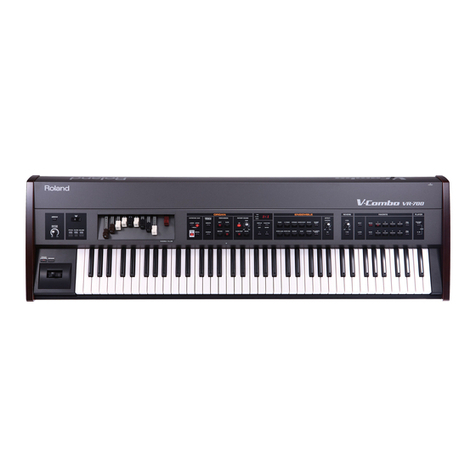
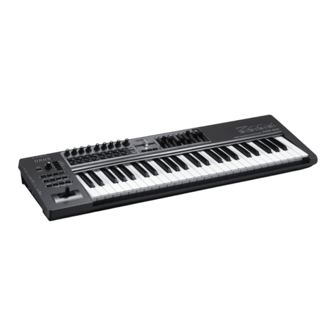
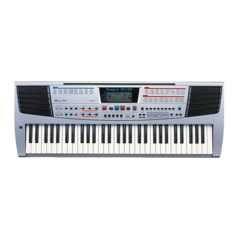
A-70/A-70EX : Expandable controller
A-70EX Sound Section (VE-RD1)
- Sound Generator PCM synthesis
- Parts 4 Parts
- Maximum Polyphony 64 Voices.
- Effects Reverb
Chorus
Equalizer
- Preset Memory Patches : 128
A-70/A-70EX Common
- Keyboard 76 Keys
- Zones Internal : 4
External : 4
- Internal Memory System Setup : 1
User Name Maps : 4
Preset Name Maps : 9
Performances : 64
Chains : 10
Manual : 1
- Display 3 Characters (backlit LCD)
17 Characters, 2 Lines (backlit LCD)
.-Nominal Output Level Output : -7dBm.
- Output Impedance Output : 1600 Ohm.
- Recommended Load Impedance Output : 10 Kohm or Greater
- Connectors Midi Connectors (in:2, thru:1, out:4)
Foot Controller Jacks:1
Switch Jacks:1
Total Volume Pedal Jack
Hold Pedal Jack
Output Jacks [L(Mono), R]
Headphone Jack
AC Inlet (AC 100V, AC 230V, AC 240V)
- Power Supply AC 100V, AC 117V, AC 230V or AC 240V
- Power Consumption 15W (AC 100V), 17W (AC 117V)
20W (AC 230V), 20W (AC 240V)
- Dimensions 1245(W) X 357 (D) X 136 (H) mm
- Weight 16 Kg
- Accessories Pedal Switch:DP-2 (7710610000)
Owner’s Manual (E) (K6018288)
Owner’s Manual (J) (K6018291)
Midi Guide (K6018109)
Midi Implementation Manual (K6018292)
! MAINS CABLE H05VV+POL.SOCKET 230V (J3439150)
! CABLE 49B/35JT 2X18 AWG-C17 117V (J3439128)
! MAINS CABLE DC 545 J03 100V (13499108)
! CABLE BS/13/H05VV-F3G 0.75-V 230VE (13499152RI)
! CABLE SAA/3-OA3CCFC 3X0.75-V 240VA (13499150RI)
- Options Stereo Headphone : RH-20/80/120:
Pedal Switch : DP-2/6, BOSS FS 5U
Expression pedal : EV-5
Connecting Cable : PJ-1M, PCS-100PW
MIDI/SYNC cable : MSC-15/25/50
Voice Expansion board : VE series
Issued by RES
Copyright © 1997 by ROLAND CORPORATION
DISASSEMBLY
1SN00018 K6018299 Printed in Italy (AF00) (AD)
First Edition
