manuals.online logo
Brands
  1. Home
  2. •
  3. Brands
  4. •
  5. Roland
  6. •
  7. Synthesizer
  8. •
  9. Roland Alfa JUNO-2 User manual

Roland Alfa JUNO-2 User manual

Roland
•n PROGRAMMABLE POLYPHONIC SYNTHESIZER
JUNO-S
Owner's Manual
The Ij^lning flash wflh arruwhmd symbol, within anM^llatwal
tnan^, is Attended to alert i\B user to the preswKS cA un-
insulated "duiQerous voKage" wtthin the prokict's encksurs
that may tw of suffictent magnttude to constitute ari^ o(
electric shock to persons.
"me exdamatiOT fxMwt&m an equ^ateral Irian^e ebitended
to aien the user to ttw (MBsence or irr^xirtant operalbig and
iTuMntenance (sen^rig) instnjcttons in the lileratira aaxm-
p»iying the producL
IINSTRUCTIONS PERTAINING TO A RISK OF FIRE, El£CrmiC SHOCK OR INJURY TO PERSONS. |
IMPORTANT SAFETY INSTRUCTIONS
WARNING Whaiiraing^ectric products, basic precau-
tiot% ^tkaM ^ways be followed, ^ichidlng
ttnfoHowing;
1. Read aR the instoK^ons before usb^ the product
2. To reduce the d^ t^ ir^ury, dose si^iervision Is
necessoy wrtien aproduct is used nea^ c^iBdren.
3. Oo not use this pnxkxi near wtfer- for exarr^,
nwu- abatrmib. wa^ibowl. kitchen sir^, ^aw^
tfflsement, or near aswbnmJng pool, or the tike.
4. lYis f»oduct shouki be used only with acart or
steuid that ts recommended by (he mareifacture.
5. This product, either ^one or in onnbinalion wtth an
amplifia- and haat^ihones or spacers, may be
capable of (MtMludng sound levete that couki causa
permanerd hear^ loss.
Oo not opiate Im^ along period of time at af^
vfAjme level weU level ^iai is unoxntortedsle. If you
eiqwrienca any heamg kiss or ringing mflie ears,
you shouki cansm an audkikig^.
6. THepnx&JdshoUdbekxaledso&uaHskKattonor
po^iwi does ncri irrterfwe w^ its fvoper venmatkMi.
7. The pn3duct ^wuid be kxated away from heat
sources such as racBalors, hmd registers or other
producte that produce heat
a. The product shoidd avcM using in where it may be
effected by (Ktst.
9. The product ^vx^ be connected to apower stqjpty
orriy of the type descdtied in ^opetaling ktsHnjc-
tons or as marited on Itw prockKt
fO. The power-si^ipty ccvd (rf the product shoi^ be
itfiphiggad from the ouUet whan left unused for a
kxig perkxJ of tbne.
11
.
Do not tread on tha power-su[^ cord.
12. Do not pull the cmxi but hold the plug when
unptug^ng.
13. \Mwn se^ng up wSh my o6m ratnmer^, the
procechra should be lonowed in accordance v^Qi
ftisbudion meviual.
14. Cera shouki be taken so thaa d]^ects do ncM fan and
Ik^kte arB not spilled into the endosura thnw^
t^wnlngs.
15. The pro(hict ^KHikl be ser\riced by edified s^vice
personnet whw:
A: The poww-supf^ cord or the plug has been
d»n^|ad: or
B: Objects have ftilen, or Hqiid has been spilled
mo the product; or
C: The pn)^ict Ivis been exposed to rain; or
D: The product does not appear to operate
nomi^ly or exhHsits anwksd change in p«1or-
manca:or
E: The product has been drc^iped. or meendowre
damaged.
16. Do not atlerr^ to sarvica the procfejct b^ond that
d^crttied hHw user-m^itenaf%» insbuctions. All
other senndng #Kxdd be r^ened to c^iaHfied senrice
pwsormel.
SAVE THESE INSTRUCTIONS
WARNING
THIS APPARATUS MUST BE EARTH GROUNDED.
The three conductors of the mains
lead atta:hed to tiiis apparatus are
identified with color as shov^n in the
table bek)w. toother with the
matching temiinat on ttw UK type
power ^ug. Wlien connecting the
mains lead to ar^t^, be sure to
connect each conductor to the cor-
rect terminal, as indicated.
'Hite imtructiiHi apples to the
fHToduet for United Klnadom."
MAINS LEADS PLUG
Conductor Color Mirit on the mstchlng terminal
Uva Brown Rwl or htur L
Nautili Bluo Black or latter N
Groundbio GrHO-
VBllOW Giaen. Graen-Yellow, lattar E
or symbol
Beicbeinioung dtt HerstellBrs /Irnportmn
Hinmit wird bes^winigl, daQ der/dic/dat
ROLAND POLYPHONIC SYNTHESIZER JU-2
in Obereinitimmung mit den Bnttmmungen der
Amtsbl. Vfg 1046/1984
lAnmUfftmrtiigunil
funlcenatwt isi.
Dh OButtchen Bundeipost wuida d« Inwki^rbringen dines GeritH
•ngeuigt und di« Bwichtigung zur Qberprii^ng der Saria nit Einhiltung
der Bettimmungan Bing«riumt.
RoiarKl Corporation Osaka /Japan
RADIO AND TEifVISION INTERFERENCE
'WamtoB -TNI* oquipmanl hai tean varifwd lo comply oHh iha ItmHB lot CMli BEompuUng davtea.
IHiruiani lu Sulipan J. o* Pan IS. ol fCC mm. ^aration lOHh RDn«anilla« o- -'—
IT •Clau Bceminitina
Thl» BouvnuH ha» b
oaviCB w(cconlanca «Mih IM iptcilieationt mSutvM J. of fan IS, of HX Ri^aa TIwm nilaa art
aawsnad Kprauala rauumabM unriaatun agmniu «ikM atraaHaranea nnnMHiUil inHMHKin
HotHoar. Dtara Nno Buarantaa that itw imaWatanea wUI noi dccui in paiMular inaiaUaiMn. 11 ihli
attuipmanl Ooai Eauaalmarfaranea la '*« or tatavialm raeafi^an. whiEh can b* iMarniinatt 1^ luming
md all. Iha ibmk •* ancouranad lo tn- id UHtao Ilia tmartatanea tw Iha
la ona uda or iha mhmi dI iha TV or ladia.
fanhar awav (rhti iha TV at imJid.
Mia an oullBI Iha) «on diTfaiani a
Tim tuniUal na*a<laMic tiom tha U.S. Qnvarnmani IVmimg Otfica, Withtnglm. DC. TtMOI,
Please read the separate volume before reading this owner's manual
Copyright ©1985 by ROLAND CORPORATION
All rights reserved. No part of this publication may be reproduced in
any form wnthout the written permission of ROLAND CORPORATION.
i
in
z
g
t
o
(0
LU
Q
_l
uu
Z
2
s
sJ1
o^1
^..-'^
@
1m1iP
IP
iP
ii
li
•a
o'ii
X-U
0)
en
^
o
£
o
£
Ti
1
3)
£
10)
"S p3
1ia
1©Oi
gs1Ola
(Q fc^ V^<'
o
"2 E
=1
.s ®
!? 1*.W! tr
aD. ^t
X
Ul
®
1
1
«1
S1
"> -s
Xjj 1
1i-S r- »..!
3"8-i M
Si -SZ
SS
Io^11
®©
I(0
0^
1%
10
e
u
a
e
m
OO 3
eBcgOil
III"I
II i5® '
g©
11
11
11
1
1^
1
1ll
1II
|CZZ1
1= 2
Z
o
u
o
in
Ml
5
z
I-
z
o
a.
m'
t"" s^fe
2?
{0 >
.. rSf%
Vi >Tl gSi
1.ti
ca)
F c
l-S
•n Sr
S
11
tn
Ji
fF?,F
ii
'.M
e5 .2 g
is
its
OD>
1!
to s
Tt!
ii
Ta
S
C
Rl
O
DC
1
O
a
I
\
0) W
=t: n01
tx> XI a>-*i
(0 £C
i? "S o
U"O Q
w
O
Z
^-d
!i
o?: =
-5 CD 5j
Sff 5
k£ E
!„XI
j0, >-D
?°*\
:_0) ro
:'^^ E
to
0} CO
£E
%E
IS —
fli t;
Oo
la "L.
o> »S-
OITI SOl
goE?
£0) ag£
?i Is,
<Jda
°> HI
k- CD
£E
R3
s&
SS
x: «
en 5£•
3>»-
a"c ~:
QJ a:
E^ti »
'OJ 0) J£ E
J£S o5,
)'ft a5»_ •
-°c;S a>
EfSf"
301 P:;::
SI C
'S (0
^l
»o«. I|-= I-
Pm£> to~K o
.K s3^=
m
x: o
eo:?
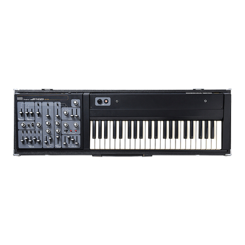
The aJUNO-2 is 61 key, 6voice polyphonic,
fully programmable synthesizer with Dynamics
and Aftertouch functions.
•The Liquid Crystal Display and the aDial serve
to make the editing operation quicker and more
accurate.
•The Tone Modify Function of the aJUNO
allows you to edit the tone color easily to your
taste.
Provided with MIDI Connectors, the aJUNO
can be set up with other MIDI devices.
The optional Memory Cartridge (M-64C) can
expand the aJUNO-2's memory capacity by 64
tone colors.
CONTENTS
Q] PANEL DESCRIPTION 3
[2] CONNECTION 5
[J] OPERATION 6
1. Power Up 6
2. Tone Color Selection 6
3. Performance Control Functions 8
a. Pitch Bender/Modulation 8
b. Portamento 8
c. Octave Transpose 9
d. Chord Memory 9
e. Key Transpose 11
f. Hold Pedal Jack 12
g. Pedal Switch Jack 12
h. Expression Pedal Jack 12
4. Tone Modify 13
5. Editing Performance Control
Function 14
a. How to edit the Performance
Control Functions 14
b. Writing the Performance Controll
Functions 16
6. Edit 17
7. Tone color parameters 18
a. Synthesizer Structure 18
b. Parameters 19
8. Writing aTone Color 29
9. Naming the Tone Colors 30
10. MIDI 31
a. Changing MIDI Function Data 32
b. Writing MIDI Function Data 33
c. aJUNO'S Sound Range receivable
and transmissible with MIDI 34
d. Pedal Switch 34
e. Program Change Messages 35
11. Data Transfer 36
a. Saving into the Cartridge 36
b. Loading from the Cartridge
to the Memory Group 37
c. Data Transfer with MIDI 38
BAPPENDIX 40
1. Parameter Table 40
2. Error Message Table 43
3. Memo 44
BSPECinCATIONS 47
2] Connection
r~ IRoland odoe6os o 6"6
Refer to page 31 "MIDI".
Memory Cartridge Usually, this should be
M-64C (Option) set to the ON position
i..
S^?? '^ ^
Expression Pedal Switch Stereo
Pedal EV-5 DP-2 Headphones
(Optional) (Optional) RH-10
(Optional)
ot T
Amplifier o
¥1 OPERATION
1. Power Up
®Make sure that the Memory Protect
Switch ®on the rear panel is set to the
ON position.
(2) Turn the Power Switch ©on.
The Display Window ®will respond with:
This is shown for afew seconds
\
Then the Display changes
u
Tone Name
2. Tone Color Selection
Any of the 128 different tone colors (192 tone col-
ors when the optional Memory Cartridge is used)
can be called by using the Group Selector Button
®, the Bank Selector Button Qand the Number
Selector Button ®.
®Bank Selector Buttons
t !
©Group Selector Buttons ©Number Selector Buttons
The Display ®shows the tone color currently
selected
:
J. J.
4i *
Group Bank Number Tone Name
Ml MHQK1 CllmOCI \^ Number
Bank\ 12 345678
1Mil
1 1
3
1 1 1 1 1 1 1
pppCPT 1
-* <!
1 1 11
1
5._
i
6
7
8_j
1
\^ Number
Bank\ 12 34 5678
1Mil
2Zl
3
MORY —4
HII
6
7
1 1
8
N^^ Number
Bank \I234 b t> ?8
I
1
2
3
11
41111 1
CARTRIDut HIM
611 1 H
7III 1
8II 11
<OPERATION>
©By pressing the appropriate Group Selec-
tor Button ®, select Preset, Memory or
Cartridge group.
PPreset Group
The tone colors in this group can be modified, but
the modified patch cannot be written into memory.
M.. Memory Group
The tone colors in this group can be modified and
even rewritten.
CCartridge Group
Select this group for using the optional Memory
Cartridge M-64C. The tone colors saved in the car-
tridge can be modified and rewritten. The car-
tridge can be removed from the aJUNO-2 and
used later at any time.
(2) Select the Bank (1 to 8) by pressing the
relevant Bank Selector Button ©
(3) Select the Number (1 to 8) by pressing the
relevant Number Selector Button ®.
Now, by using the Volume Knob ©,adjust the
volume of the sound.
*The above procedures (T) to (3) can be done in
any order you like.
:Preset: Bank 5, Numbers
P: Memory: Bank 2, Numbers
^:Cartridge: Bank 6, Number 8
3. Performance Control Functions
a. Pitch Bender/Modulation
By bending the Pitch Bender/IVIodulation Lever©,
guitar's bending like effect can be obtained. At its
center position, this has no effect on the sound,
while the left and right extremes of movement
achieve the same amount of the pitch bend effect.
Also, by pushing the same lever forward, vibrato
effect is obtained.
MODULATION
A
T—
r
PITCH BENDER
>The range of each tone color's Pitch Bender
effect can be changed, if the tone color is in the
Preset Group, see page 14 "Editing the Perfor-
mance Control Functions", and if it is the one in
the Memorv Group, see page 17 "6. Edit".
*The depth of the Modulation can be changed as
shown on page 14 "Editing the Performance
Control Functions".
b. Portamento
Portamento effect is aslide from one pitch to
another. This may be effectively used for the per-
formance with the Chord Memory function.
<OPERATION >
To turn Portamento on:
'/W*
To turn Portamento off:
PORTA-
M^Tro
Push the Portamento Button O
The indicator lights up.
Push the Portamento Button (
again.
The indicator goes out.
*The time needed for asound to move from a
pitch to another (Portamento time) can be
changed as shown on page 14 "Editing the Per-
formance Control Functions".
c. Octave Transpose
The entire keyboard can be transposed one octave
down.
<OPERATION>
To set Octave Down
Transposition
Push the Down Button of the
Octave Transpose Buttons 0.
The indicator lights up.
To return to Normal
NORMAL
Push the Normal Button of the
Octave Transpose Buttons Q.
The indicator lights up.
d. Chord Memory
Chord data can be recorded and later played with
one finger.
Example
^^ ^m <>
C4 E4 Gil
Octave Transpose; Normal
Key Transpose:
"i
^^
r^
•When C4 key is played, the actual chord you hear is exactly in the same pitch
as the recorded one.
<OPERATION>
To set to the Chord Memory mode
-Mm'.
CHORD
MEnOR^
Push the Chord Memory Button i
The indicator lights up.
To return to the Normal mode
C3
Push the Chord Memory Button (
again.
The indicator goes out.
•How to record Chord Data used for Chord Memory Function
When achord data is recorded into the aJUNO
with the Memory Protect Switch set to the ON
position, it is erased by power off. If you wish to
retain the recorded chord data even after power
off, you should record it with the Memory Protect
Switch ®set to the OFF position.
<OPERATION>
©Set the Memory Protect Switch as shown
below. @Play the chord you wish to record.
When all the keys are released, the chord data is
recorded, and the Display ®will respond with
:
Memory Protect Switch ®: ON —
»
Erased when the power is off.
When the Memory Protect
Switch is set to ON.
Memory Protect Switch ®:OFF -
f?etained even after the power is off.
When the Memory Protect
Switch is set to OFF.
(2) Press the Write Button ®while holding
the Chord Memory Button Odown. ®If necessary, return the Memory Protect
Switch to the ON position.
The Display ®will respond with
:
*While achord data is being recorded, the Octave
Transpose or Key Transpose function does not
work, therefore, the middle Ckey always works
as C4 key.
*When the recorded chord is being played, the
Octave Transpose and Key Transpose functions
work. When Octave Transpose is normal and
the Key Transpose is 0, playing the 04 key will
faithfully recall the recorded chord.
*By recording the C4 key, the aJUNO can be
played as amonophonic keyboard.
*If the keyboard is being played extremely fast
or too many NOTE ON messages are continu-
ously sent into the MIDI IN, the chords may not
properly sound.
10
e. Key Transpose
The keyboard can be transposed to any key you
like within ±an octave (-12 to +12 value). There-
fore, you can play music in various keys without
using different keys.
*This Key Transpose operation cannot be done
unless ttie Display ®is showing atone name
and no key is played on the keyboard.
How to Transpose
1. Using the uDial O
®Push the Key Transpose Button O
2. Using an appropriate key
®Push the Key Transpose Button .
czi
The value (j.i )shown in the Display repre-
sents how many semi-tones (keys) are currently
transposed.
The value (i.;;i )shown in the Display repre-
sents how many semi-tones (keys) are currently
transposed.
@While holding the Key Transpose Button
Qdown, rotate the aDial to set the
desired value. (Refer to the picture shown
below.)
The Display ©shows the corresponding value,
and if it is other than 0, the indicator lights up.
(D While holding the key Transpose Button
©down, push the key to which you wish
to transpose.
The Display ©shows the corresponding value,
and if it is other than 0, the indicator lights up.
11
E<T CONTROL
ON OFF ON
f. Hold Pedal Jack
The aJUNO features the Hold effect that can
retain the sound even after the key is released.
Using the optional Pedal Switch DP-2, the Hold
effect can be turned on or off.
g. Pedal Switch Jack
Using the optional Pedal Switch DP-2, the function
selected at "Editing Performance Control Func-
tions" on page 14 can be controlled.
*Program Shift function is set at the factory. Pro-
grams Shift is the function of calling tone colors 1
to 8sequencially.
When "M-13" is initially set, the Tone Number will
change as shown below.
\
ri-i3
H'
M-14
15;
n-15
i'3>
M-16
i*
M-l?
^5^
1CO
.6^
Irl™. '!
ic?)
M-12
1
'^'
PEOAt SW MOLD I«>«
O@O@Oo
noland
ev-B
m
Expression Pedal
EV-5
(Optional)
Pedal Switches
DP-2
(Optional)
^
ON 4- OFF-|^
h. Expression Pedal Jack
By using the optional Expression Pedal EV-5 to
this jack, the volunne can be controlled.
12
4. Tone Modify
TONE MODIFY
MOD RATE MOD DEPTH BRILLIANCE! ENV TIME
Several parameters of atone color can be simul-
taneously changed with a simple operation. There
are four modes for the Tone Modify.
Mode Tone Modifty
Mode Button® Function
Modulation Rate BB This mode changes the rate ofthe vibrato, growl or chorus effect.
Modulation Depth BBSS This mode changes the depth of the vibrato or growl effect.
Brilliance gsm This mode changes the brilliance ofthe sound.
Envelope Time mm This mode changes the time needed for atone color to change
from the momentthe key is played.
<OPERATION>
©Call the tone color you wish to edit.
(D Select one of the four modes by pushing
the corresponding Tone Modify Mode
Button ®.
The Display will respond as shown right:
Modulation Rate T
(D Using the aDial O, modify the tone color
to your taste.
Rotating the aDial will change the Display ®as
shown below.
Rotating it counterclockwise -a Dial I
r=iij|ji |:;;:i:jrE h-:
Modulation Depth
HOD ij^F'Ti-i '.;.
Srilliance T
c:r".L..L.r-n -p..;:::. ;.;.;
Envelope Time
:" ":. :: :"~ Ty.".:""
CI •••.' :-i. 1 n.... 'A\
Rotaf ng it clockwise
Original Tone Color
'The edited tone color will be erased by selecting
adifferent tone color. To retain the edited patch,
take an appropriated writing procedure. (See
page 29.)
*This Tone Modify operation may have no effect
on some tone colors. For Instance, the tone
color without vibrato or growl effect will not
change at all even by changing the depth or rate
of the Modulation effect.
13
5. Editing Performance Control Functions
Using the Tune/Function Button ©, you can
change the settings (data) of the Tuning and other
functions for performance control. The changed
data is erased when the unit is powered off. If you
wish to retain the data even after powered off, take
an appropriate writing operation.
Parameter
1. Tuning
2. Modulation Sensitivity
3. Portamento Time
4. Preset Tone Colors' DCO
Bender Range
5. Pedal Switch
a. How to edit the Performance Control Functions
<OPERATION>
©Press the Tune/Function Button ©until
the Display ®shows the function you
wish to edit.
As shown in the picture, each time you push the
Tune/Function Button©, the function shown in
the Display changes.
(D Using the aDial, change the value of the
function to your taste.
14
1. Tuning
Example
This function is used to tune with other instru-
ment. The pitch of A4 key can be set to 430 to
454Hz.
The Display ®shows the pitch currently set, and if
"" nnark is shown on the left of the Display, the
actual pitch of the aJUNO is slightly lower than
the set pitch shown in the Display. \i"<" mark is
shown on the right side of the Display, the pitch is
higher. When both "" and "<" marks are
shown at the both ends of the Display, tuning is
done.
2. Modulation Sensitivity
Example TWhen the Pitch Bender/Modulation Lever @con-
trols the Modulation effect, this function deter-
mines the depth of the Modulation effect from to
127.
3. Portamento Time
Example TWhen the Portamento effect is on, this function
sets the time needed for the slide of the pitch from
one note to another.
*At 0, no portamento effect is obtained, and 127 is
the longest time.
4. Preset Tone Colors' DCO Pitch Bender Range
Example When the Pitch Bender/Modulation lever controls
the Pitch Bender effect of the whole preset tone
colors (P-1 1to 88), this sets the depth of the effect
from to 12 (1 represents semi-tone).
5. Pedal Switch
Example TThis function selects which of the Program Shift,
Portamento, or Chord Memory function works by
the pedal switch connected to the Pedal Switch
Jack®.
Mode Display® Function
Program Shift Pressing the pedal switch sequenclally calls the tone colors 1to 8.
After 8,1 will return.
Portamento PORTH This turns on or off the Portamento effect.
Chord Memory CRD HThis turns on or oft the Chord Memory effect.
When the Portamento or Chord Memory function Is selected, the effect is on while the DP-2 is being depressed.
If you wish to turn the effect on and off alternately by depressing the pedal, use the optional Foot Switch
FS-1.
15
b. Writing the Performance Control
Functions
If you wish to retain the data of Tune/Function
even after the aJUNO is switched off, you should
write it in the back-up memory.
OPERATION
®Set the Memory Protect Switch ®to the
OFF position.
(2) Push the Tune/Function Button @
.
(D While holding the Write Button ®down,
press the Tune/Function Button ©.
The Display ®will respond with
:
While holding the Write Button ®down
\
When the Tune/Function Button ©is pushed.
®Return the Memory protect Switch ®to
the ON position.
16
6. Edit
Here, call each parameter of atone color and
change it. Regarding the details of the parameters,
see page 18 "7. Tone Color Parameters".
<OPERATION >
®Call the tone color you wish to edit.
(2) Push the Parameter Selector Button <
The Display will respond with:
Example
iV
®Push the Value Button ®.
As shown in the picture, on the right of the Display
®, the current value and the prospective value are
shown.
Example
Parameter Name value Previously set value New value
(D Using the aDial O,call the parameter you
wish to change. (D Using the aDial O, change to the value
you like.
(D Repeat the steps (5) to (5) as many times
as necessary.
17
7. Tone Color Parameters
Atone color consists of various parameters, there-
fore, to edit atone color, change the values of
those parameters.
a. Synthesizer Structure
The aJUNO's synthesizer section consists of
several blocks as shown in the picture. Each
block of the synthesizer section is controlled by
relevant tone-color parameters.
»Audio Signal
Control Signal
®
DCO Block HPF
Block
®
VCF Block ®
VGA Block
®
Chorus
Block
.I,1 . .1. L 1 .1,
®
LFO
Block
.®
ENV Block
L, Jw
'
]
Modu
Lever
lation P
B
tch
ender Ke Y
iyboard
Output
(D DCO (Digitally Controlled Oscillator)
DCO is the digitally controlled oscillator that con-
trols the pitch and generates the waveforms that
are the sound source of the synthesizer.
(D HPF (High Pass Filter)
The HPF (High-Pass Filter) is afilter that passes
high frequency harmonics and cuts off the lower
ones. This changes the waveform and controls the
tone color.
(3) VCF (Voltage Controlled Filter)
Each VCF lets lower frequency harmonics of the
input signal pass and cuts off the higher ones. In
other words, it is ausual low pass filter. By con-
trolling the cutoff point and resonance, the
waveform changes, thereby the tone color alters.
®VCA (Voltage Controlled Amplifier)
After filtered in the VCF, the signal is fed to the
VCA where the volume (amplitude) of the sound Is
controlled.
(5) CHORUS
®LFO (Low Frequency Oscillator)
This oscillator generates extremely low frequency,
so produces avibrato or growl effect by control-
ling the DCO or VCF.
®ENV (Envelope Generator)
This generates the control voltage (Envelope)
which controls the DCO, VCF and VCA, therefore,
alters the pitch, tone color and volume in each
note.
18
b. Parameters
DCO (Digitally Controlled Oscillator)
DDCO Range
Example T
This is to change the pitch range of the DCO in
exact one octave steps from 4' to 32' (4', 8', 16',
32'). 8' is standard.
^z
8va
^_!_i2._4'
^—^-8' (Standard)
I2gr=,ffl3-16'
--S'--32'
yy
1
fflHI!!111
oJUNO-2's Keyboard
1Octave Transpose: Normal \
Ikey Transpose: '
DDCO LFO Depth
Example T
aDCO ENV Depth
Example T
When the LFO is controlling the pitch of the DCO,
this adjusts the depth of the vibrato effect in the
range of to 127.
When the ENV is controlling the pitch of the DCO,
this parameter sets the depth of the modulation in
the range of the to 127.
DDCO ENV Mode
Example TThis selects the polarity of the Envelope curve that
controls the DCO. Usually /V may be used. In \y
mode, ADSR pattern will be inverted.
Mode Display® Function
Normal I"--". ENV serves to increase the DCO's pitch.
Invert i--- ENV serves to decrease the DCO's pitch.
Normal with
Dynamics [j!-.-. The ENV with Dynamics serves to increase the DCO's pitch.
Invert with
Dynamics Di-- The ENVwith Dynamics serves to decrease the DCO's pitch.
19
DDCO Aftertouch Sensitivity
Example TThis parameter determines the depth of the vibrato
effect when it is controlled by aftertouch. to 15
are valid for this parameter.
DDCO Bender Range
Example
This sets the maximum effect of the Pitch Bender
caused by moving the Pitch Bender/Modulaion
lever. to 12 are valid for this parameter, and 1is
semi-tone, therefore, 12 is an octave.
aDCO Pulse Waveform
Example
Pulse wave is selected.
Display Waveform Spectrum
:;.•:!.- OFF ^^^^
LJI :!,;: 'L
:":"=
1niMH.
Pi.': 1!"n
See page 21
-DCO PW/PWM
Depth"
*The pulse width of 03 can be set at DCO PW/PWM
Depth.
aDCO Sawtooth Waveform
Example T
Sawtooth waveform is selected.
Display Waveform Spectrum
wOFF ^^^---^^
l."'l 1/-I
:'": •"*:
=:..=.::.. _nil 1
..:ddl See page 21 "DCO
PW/PWM Depth"
:;!-"i .iiiilil L^^...-
:"'i!"'i ,ill
The pulse width of 03 can be set at DCO PW/PWM
Depth.
20

Other Roland Synthesizer manuals

Roland JV-50 User manual

Roland

Roland JV-50 User manual

Roland JUNO-Gi User manual

Roland

Roland JUNO-Gi User manual

Roland Fantom-S User manual

Roland

Roland Fantom-S User manual

Roland GK-1 User manual

Roland

Roland GK-1 User manual

Roland TB-303 User manual

Roland

Roland TB-303 User manual

Roland EP-20 User manual

Roland

Roland EP-20 User manual

Roland Jupiter-50 User manual

Roland

Roland Jupiter-50 User manual

Roland JUNO-106 Operating and maintenance manual

Roland

Roland JUNO-106 Operating and maintenance manual

Roland KIWI-3P User manual

Roland

Roland KIWI-3P User manual

Roland MKS-50 User manual

Roland

Roland MKS-50 User manual

Roland Lucina AX-09 User manual

Roland

Roland Lucina AX-09 User manual

Roland G-800 Operating and maintenance manual

Roland

Roland G-800 Operating and maintenance manual

Roland MKS-50 User manual

Roland

Roland MKS-50 User manual

Roland JUPITER-X User guide

Roland

Roland JUPITER-X User guide

Roland JUNO-Gi User manual

Roland

Roland JUNO-Gi User manual

Roland SH-32 Manual

Roland

Roland SH-32 Manual

Roland JX-08 User manual

Roland

Roland JX-08 User manual

Roland JP-8080 Operating and maintenance manual

Roland

Roland JP-8080 Operating and maintenance manual

Roland EXR-40 or User manual

Roland

Roland EXR-40 or User manual

Roland V-Synth User manual

Roland

Roland V-Synth User manual

Roland Fantom-Xa Manual

Roland

Roland Fantom-Xa Manual

Roland XV-88 User manual

Roland

Roland XV-88 User manual

Roland SPV-355 User manual

Roland

Roland SPV-355 User manual

Roland D-550 Operating and maintenance manual

Roland

Roland D-550 Operating and maintenance manual

Popular Synthesizer manuals by other brands

Kilpatrick Audio K4815 user manual

Kilpatrick Audio

Kilpatrick Audio K4815 user manual

Personal Circuits Midi-CV-8 user guide

Personal Circuits

Personal Circuits Midi-CV-8 user guide

Dave Smith Instruments Prophet Rev2 user guide

Dave Smith Instruments

Dave Smith Instruments Prophet Rev2 user guide

Polyend & Dreadbox Medusa user manual

Polyend & Dreadbox

Polyend & Dreadbox Medusa user manual

Keysight Technologies N5221BU-665 manual

Keysight Technologies

Keysight Technologies N5221BU-665 manual

Hammond XLK-3 owner's manual

Hammond

Hammond XLK-3 owner's manual

NTHSynth NTH Music Synthesizer user manual

NTHSynth

NTHSynth NTH Music Synthesizer user manual

Korg DS-8 owner's manual

Korg

Korg DS-8 owner's manual

Yamaha SY85 Job Table

Yamaha

Yamaha SY85 Job Table

Yamaha MX49 Data list

Yamaha

Yamaha MX49 Data list

DOEPFER A-190-2 manual

DOEPFER

DOEPFER A-190-2 manual

Korg DW-8000 owner's manual

Korg

Korg DW-8000 owner's manual

Oberheim OB-Mx user guide

Oberheim

Oberheim OB-Mx user guide

Wurlitzer 140 Service manual

Wurlitzer

Wurlitzer 140 Service manual

Modal CRAFTsynth 2.0 user manual

Modal

Modal CRAFTsynth 2.0 user manual

TINRS RectangularThing manual

TINRS

TINRS RectangularThing manual

Crumar MOJO CLASSI user manual

Crumar

Crumar MOJO CLASSI user manual

Synthesis Technology MOTM-485 GX-1 Diode VCF Assembly instructions & owner's manual

Synthesis Technology

Synthesis Technology MOTM-485 GX-1 Diode VCF Assembly instructions & owner's manual

manuals.online logo
manuals.online logoBrands
  • About & Mission
  • Contact us
  • Privacy Policy
  • Terms and Conditions

Copyright 2025 Manuals.Online. All Rights Reserved.