manuals.online logo
Brands
  1. Home
  2. •
  3. Brands
  4. •
  5. Roland
  6. •
  7. Synthesizer
  8. •
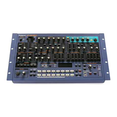
  9. Roland JV-880 User manual

Roland JV-880 User manual

Other manuals for JV-880

2

Other Roland Synthesizer manuals

Roland GR-20 User manual

Roland

Roland GR-20 User manual

Roland System-8 User manual

Roland

Roland System-8 User manual

Roland Fantom XR Operating and maintenance manual

Roland

Roland Fantom XR Operating and maintenance manual

Roland KIWI-3P User manual

Roland

Roland KIWI-3P User manual

Roland JX-10 User manual

Roland

Roland JX-10 User manual

Roland JUNO-60 User manual

Roland

Roland JUNO-60 User manual

Roland JD-990 User manual

Roland

Roland JD-990 User manual

Roland SH-101 Operating and maintenance manual

Roland

Roland SH-101 Operating and maintenance manual

Roland JX-BP User manual

Roland

Roland JX-BP User manual

Roland AX-Synth User manual

Roland

Roland AX-Synth User manual

Roland System-8 User manual

Roland

Roland System-8 User manual

Roland Gaia SH-01 User manual

Roland

Roland Gaia SH-01 User manual

Roland MKS-30 Operating and maintenance manual

Roland

Roland MKS-30 Operating and maintenance manual

Roland XP-10 Operating and maintenance manual

Roland

Roland XP-10 Operating and maintenance manual

Roland Groovebox MC-505 User manual

Roland

Roland Groovebox MC-505 User manual

Roland GR-33B User manual

Roland

Roland GR-33B User manual

Roland SonicCell SCWS02 Instruction manual

Roland

Roland SonicCell SCWS02 Instruction manual

Roland D-10 User manual

Roland

Roland D-10 User manual

Roland SonicCell Assembly instructions

Roland

Roland SonicCell Assembly instructions

Roland syb-5 Operating and maintenance manual

Roland

Roland syb-5 Operating and maintenance manual

Roland JV80 User manual

Roland

Roland JV80 User manual

Roland JUNO-60 Operating and maintenance manual

Roland

Roland JUNO-60 Operating and maintenance manual

Roland E-10 User manual

Roland

Roland E-10 User manual

Roland BK-9 Performance Editor User manual

Roland

Roland BK-9 Performance Editor User manual

Popular Synthesizer manuals by other brands

NEON CAPTAIN Radioator user manual

NEON CAPTAIN

NEON CAPTAIN Radioator user manual

Joranalogue Contour 1 user manual

Joranalogue

Joranalogue Contour 1 user manual

Full Bucket Music Mono/Fury manual

Full Bucket Music

Full Bucket Music Mono/Fury manual

IK Multimedia UNO Synth PRO X user manual

IK Multimedia

IK Multimedia UNO Synth PRO X user manual

Kawai MP7 Software update

Kawai

Kawai MP7 Software update

Behringer DEEPMIND 12 quick start guide

Behringer

Behringer DEEPMIND 12 quick start guide

Yamaha S90 ES owner's manual

Yamaha

Yamaha S90 ES owner's manual

Moog Minitmoog 300A Owner's service manual

Moog

Moog Minitmoog 300A Owner's service manual

Gotharman Gotharman's anAmoNo-box user manual

Gotharman

Gotharman Gotharman's anAmoNo-box user manual

QuStream HDFS-550 Technical manual

QuStream

QuStream HDFS-550 Technical manual

Yamaha V50 Authorized product manual

Yamaha

Yamaha V50 Authorized product manual

Akai AX80 Operator's manual

Akai

Akai AX80 Operator's manual

Octave Cat SRM Service manual

Octave

Octave Cat SRM Service manual

Dreadbox Murmux Initiate manual

Dreadbox

Dreadbox Murmux Initiate manual

neutral labs ELMYRA 2 Build guide

neutral labs

neutral labs ELMYRA 2 Build guide

Waldorf KYRA user manual

Waldorf

Waldorf KYRA user manual

EFM VCADSR - 3510 manual

EFM

EFM VCADSR - 3510 manual

Yamaha MOTIF XF Reference manual

Yamaha

Yamaha MOTIF XF Reference manual

manuals.online logo
manuals.online logoBrands
  • About & Mission
  • Contact us
  • Privacy Policy
  • Terms and Conditions

Copyright 2025 Manuals.Online. All Rights Reserved.

Roland
MULXI TIMBRAL
SYNTHESIZER MOnULE
JV-BBD
OWNER'S MANUAL
C~^ Roland JV-QBa^^^'rJ^ns'^
PHONES V01.UME
ooEDIT SVSTEM RHYTHM UTILITY If
^31 fc±±3:i[ci±jig^iig°°?!
-TONg SWITCH.
\T—nr"^ EZa t:^'mtr^-^rr-'--m-^-^
O
o
RISK OF ELECTRIC SHOCK ^m
IDO NOT OPEN I^HJ^k
ATTENTION :risque de choc electrique ne pas ouvrir
CAUTION: TO REDUCE THE RISK OF ELECTRIC SHOCK,
DO NOT REMOVE COVER (OR BACK).
NO USER-SERVICEABLE PARTS INSIDE.
REFER SERVICING TO QUALIFIED SERVICE PERSONNEL.
A
A
The lightning flash with arrowhead symbol, within an equilateral
triangle, is intended to alert the user to the presence of un-
insulated "dangerous voltage" within the product's enclosure
that may be of sufficient magnitude to constitute arisk of
electric shock to persons.
The exclamation point within an equilateral triangle is intended
to alert the user to the presence of important operating and
maintenance (sen/icing) instructions in the literature accom-
panying the product.
INSTRUCTIONS PERTAINING TO A RISK OF FIRE, ELECTRIC SHOCK, OR INJURY TO PERSONS.
IMPORTANT SAFETY INSTRUCTIONS
WARNING —When using electric products, basic precautions should always be followed, including the following:
1
.
Read all the instructions before using the product.
2. Do not use this product near water —for example, near a
bathtub, washbowl, kitchen sink, in awet basement, or near
aswimming pool, or the like.
3. This product should be used only with acart or stand that is
recommended by the manufacturer.
4. This product, either alone or in combination with an amplifier
and headphones or speakers, may be capable of producing
sound levels that could cause permanent hearing loss. Do
not operate for along period of time at ahigh volume level
or at alevel that is uncomfortable. If you experience any
hearing loss or ringing in the ears, you should consult an
audiologist.
5. The product should be located so that its location or position
does not interfere with its proper ventilation.
6. The product should be located away from heat sources such as
radiators, heat registers, or other products that produce heat.
7. Avoid using the product where it may be affected by
dust.
8. The product should be connected to apower supply only of
the type described in the operating instructions or as marked
on the product.
9. The power-supply cord of the product should be unplugged
from the outlet when left unused for along period of time.
10. Do not tread on the power-supply cord.
11
.
Do not pull the cord but hold the plug when unplugging.
12. When setting up with any other instruments, the procedure
should be followed in accordance with instnjction manual.
13. Care should be taken so that objects do not fall and liquids
are not spilled into the enclosure through openings.
14. The product should be serviced by qualified service per-
sonnel when:
A. The power-supply cord or the plug has been damaged;
or
B. Objects have fallen, or liquid has been spilled into the
product; or
C. The product has been exposed to rain; or
D. The product does not appear to operate normally or
exhibits amarked change in performance; or
E. The product has been dropped, or the enclosure dam-
aged.
15. Do not attempt to service the product beyond that described
in the user-maintenance instructions. All other servicing
should be referred to qualified service personnel.
For Canada-
For Polarized Attachment Plug
CAUTION: TO PREVENT ELECTRIC SHOCK, MATCH WIDE BLADE OF PLUG TO WIDE SLOT,
FULLY INSERT.
ATENTiON: POUR EVITER LES CHOCS ELECTRIQUES, INTRODUIRE LA LAME LA PLUS LARGE DE LA
FICHE DANS LA BORNE CORRESPONDANTE DE LA PRISE ET POUSSER JUSQU' AU fOND.
SAVE THESE INSTRUCTIONS
For the U.K.
WARNING: THIS APPARATUS MUST BE EARTHED
IMPORTANT: THE WIRES IN THIS MAINS LEAD ARE COLOURED IN ACCORDANCE WITH THE FOLLOWING CODE.
GREEN-AND-YELLOW: EARTH, BLUE: NEUTRAL, BROWN: LIVE
As the colours of the wires in the mains lead of this apparatus may not correspond with the coloured markings identifying
the terminals in your plug proceed as follows:
The wire which is coloured GREEN-AND-YELLOW must be connected to the terminal in the plug which is marked by
the letter Eor by the safety earth symbol @or coloured GREEN or GREEN-AND-YELLOW.
The wire which is coloured BLUE must be connected to the terminal which is marked with the letter Nor coloured BLACK.
The wire which is coloured BROWN must be connected to the terminal which is marked with the letter Lor coloured RED.
The product which is equipped with aTHREE WIRE GROUNDING TYPE AC PLUG must be grounded.
Thank you for purchasing the Roland JV-880 Multi Timbral Synthesizer Module. To take full advantage of this
nnodule, and to ensure years of trouble-free service, please read this manual carefully.
CONTENTS
IMPORTANT NOTES
FEATURES-
MANUAL ORGANIZATION
PANEL CONTROLS AND TERMINALS-
IV
VII
Vill
IX
IMIDI CONTROL
•Receiving MIDI Data
•Changing Patches
•Changing Performances
•Main MIDI Messages Handled by the JV-880
MODES
••2-9
•2-9
2-10
•2-10
•2-11
2-14
Section 3
PLAYING PATCHES
PATCH PLAY MODE
1.PREPARATI0MS
#Connection
#Turning On the Power
®Display Contrast
2. PLAYING THE DEMO SONGS
1-1
1-1
1-2
1-3
1-4
WHAT IS THE PATCH PLAY MODE? 3-1
3. PLAYING THE SOUNDS 1-7
Section 2
'^lilMII
THE JVS SOUND UNITS 2-1
9Patches 2-1
9Performance 2-2
9Voices and Maximum Polyphony 2-3
MEMORY- 2-4
CHORUS AND REVERB 2-6
OUTPUT 2-7
IOPERATION GUIDE
Changing patch
Changing Parameter Settings
Switching Tones On and Off ••
Preview Function
Storing Edited Patches
PATCH PLAY MODE PARAMETERS
3-2
3-2
3-3
3-4
3-5
3-5
3-6
Section 4
PLAYING PERFORMANCES
PERFORMANCE PLAY MODE
IWHAT IS THE
PERFORMANCE PLAY MODE? 4-1
OPERATION GUIDE 4-2
Changing Performances 4-2
Changing the Patch/Part Assignments 4-3
Muting the Sound of aPart 4-4
Part Monitor 4.5
Preview Function 4-5
m
Monitoring MIDI Data Reception of aPart
(Part Information)
Storing Edited Performances
4-6
4-7
Section 5
EDITING SYSTEM COMMON
PARAMETERS
SYSTEM EDIT MODE
WHAT IS THE SYSTEM EDIT MODE? 5-1
OPERATION GUIDE 5-2
PARAMETER FUNCTIONS 5-4
Section 6
EDITING PATCHES
PATCH EDIT MODE
IWHAT IS THE PATCH EDIT MODE? 6-1
IOPERATION GUIDE 6-3
Tone On/Off Switches 6-6
Preview Function 6-6
IPARAMETER FUNCTIONS 6-7
6-7
6-16
Patch Common Parametei-s
Tone parameters
Section 7
EDITING PERFORMANCES
PEaFORMANCE EDIT MODE
IWHAT IS THE PERFORMANCE EDIT MODE? "7-1
IOPERATION GUIDE 7-2
Preview Function 7-5
IPARAMETER FUNCTIONS 7-6
7-6
7-10
Performance Common Parameters
Part Parameters
Section 8
EDITING RHYTHM TONES
RHYRHM EDIT MODE
IWHAT IS THE RHYTHM EDIT MODE? 8-1
IOPERATION GUIDE 8-2
Preview Function 8-5
IPARAMETER FUNCTIONS 8-6
Section 9
WRITE OPERATION ADDITIONAL
FUNCTIONS
UTILITY MODE
ITHE UTILITY MODE 9-1
IWRITE 9-2
Patch Write 9-3
Performance Write (Pert Write) 9-4
Rhythm Write 9-5
ICOPYING DATA 9-6
Patch Copy 9-6
Performance Copy (Pert copy) 9-7
Rhythm Copy 9-9
UNITIALIZE 9-11
Patch Initialize 9-11
Performance Initialize (Pert Initialize) 9-11
Rhythm Initialize 9-12
IDATA CARD 9-13
IBULK DUMP 9-16
ITEMPORARY DUMP 9-18
ILOAD PATCH 9-19
Load Patch Single 9-19
Load Patch Group 9-20
IMEMORY PROTECT 9-22
IFACTORY PRESETS 9-23
IV
Section 10
REPeReNGE
IERROR MESSAGES
(miscellaneous messages) 10-1
TROUBLESHOOTING 10-4
PARAMETERS LIST 10-8
INITIALIZE DATA 10-14
WAVEFORMS LIST 10-18
FACTORY SETTINGS 10-19
BLANK CHART 10-25
Roland Exclusive Messages
MIDI Implementation
MIDI Implementation Chart ••
HSPECIFICATIONS
INDEX OF FUNCTIONS
AND OPERATIONS
INDEX
IINSTALLING THE EXPANSION BOARD
0-30
0-32
0-43
0-44
0-45
0-50
0-54
Copyright ©1992 by ROLAND CORPORATION
All rights reserved. No part of this publication may be
reproduced in any form the permission of ROLAND
CORPORATION.
iivir-v^n IA\i^ IiMV./ ICO
In addition to the items listed under Safety Precautions on page
please read and adhere to the following
Power supply
When making any connections with other devices, always
turn off the power to all equipment first; this will help
prevent damage or malfunction.
>Do not use this unit on the same power circuit with any
device that will generate line noise, such as amotor or
variable lighting system.
Placement
Additional precautions
©Protect the unit from strong impact.
#Never strike or apply strong pressure to the display.
#A small amount of heat will radiate from the unit, and thus
should be considered normal.
©Before using the unit in aforeign country, consult with
qualified service personnel.
lUsing the unit near power amplifiers (or other equipment
containing large transformers) may induce hum.
IThis unit may interfere with radio and television reception.
Do not use this unit in the vicinity of such receives.
Haintenance
IFor everyday cleaning wipe the unit with asoft, dry cloth
(or one that has been slightly dampened water). To
remove stubborn dirt, use amild, neutral detergent.
Afterwards, be sure to wipe the unit thoroughly with asoft,
dry cloth.
^Never use benzine, thinners, alcohol or solvents of any
kind, to avoid the risk of discoloration and/or deformation.
lemory backup
IThe unit contains abattery which maintains the contents
of memory while the main power is off. The expected life
of this battery is 5 years or more. However, to avoid the
unexpected loss of memory data, it is strongly
recommended that you change the battery every 5years.
Please be aware that the actual life of the battery will
depend on the physical environment (especially
temperature) in which the unit is used. When it is time to
change the battery, consult with qualified service
personnel.
IWhen the battery becomes weak the following message
will appear in the display: "Internal battery low". Please
change the battery as soon as possible to avoid the loss
of memory data.
#Please be aware that the contents of memory may at
times be lost; when the unit is sent for repairs or when by
some chance amalfunction has occurred. Important data
should be stored on aDATA (Memory) card, or written
down on paper. During repairs, due care is taken to avoid
the loss of data. However, in certain cases, (such as
when circuitry related to memory itself is out of order) we
regret that it may be impossible to restore the data.
VI
FEATURES
•Wide Range of Waveforms
Naturally, the JV-880 contains all the basic synthesizer waveforms; sawtooth, square, pulse,
etc. It also contains many special waveforms and digital samples.
As waveforms can be processed by FXM (Frequency Cross-Modulation), the JV-880 is
capable of functioning in the most demanding of programming applications, from recreating
acoustic instruments to generating unusual, otherworldly effects. Additional waveforms can
be added by using optional PCM Cards (SO-PCM1 series) or an expansion board (SR-JV80
series).
•On-board Digital Effects
Rich stereo effects that add spaciousness and depth to the sound can be obtained by using
the chorus and reverb sections.
•i\/l ulti-timbral Operation
The JV-880 features seven Independent synthesizer Parts and one rhythm Part. This allows
you to create ensemble performances with the JV's sound sources controlled via MIDI.
IVI uItipte Outputs
The JV-880 has two sets of stereo outputs: the MAIN OUTPUT and the SUB OUTPUT.
Using these outputs allows you to apply external effects to individual sounds.
Mernorf Gards
Internal settings can be stored for future use on optional Data Cards (Roland M-256E).
Sound data stored on aData Card can be selected at any time.
MANUAL UKUANI^A IlUN
This manual is organized according to the following outline. We do recommend that you read the entire manual; however, if you
have abasic knowledge of synthesizers, you may find it sufficient to refer only to specific sections.
Section 1Set up/ListerIng to the sounds
This section explains set up and
connection of the JV-880 for playing, use
of the ROM play feature, and how to
select and play the sound programs.
Section 2Overview
This section covers the basic structure of
the JV-880. You should read this no
matter what level of experience with
synthesizers you have.
Section 3
Section 4
Playing Patches
Playing Performances
Performance Play Mode
These sections explain the operations of
playing Patches or Performances.
Section 5
Section 6
Section 7
Section 8
Editing System Common Parameters
PH^ltlSl
Editing Patches
Editing Performances
Performance Edit Mode
These sections explain how the functions
of the various parameters and how to
change (or edit) them.
Editing Rythm Tones
Section 9
Write operation
Additional Functions
This section explains how to store (or
write) the data you've created to memory,
and covers other convenient functions
used before editing operations.
Section 10 Reference Includes Error Messages, Data list, MIDI
Implementation chart.
#Deslgnations and Conventions in tiiis Manual
The panel buttons and controls are indicated by the characters and symbols printed above (or below) them.
[Examples]
Edit button =o
System button =>
Cursor buttons ={>
EDIT
SYSTEIW
^CURSORS
Specific cursor button o\-4 CURSOR |or |CURSOR
m
PANEL CONTROLS AND
TERMINALS
[Front Panel]
Display
O
O©o
PREViewtPUSHi 1^—^^—
n
I1
[giarfejaK±?aiti^^
rr^ir^rgairg:?! t
O
o
iQj
PHONES jack
Connect stereo headphones to this jack. We recommend
the use of Roland RH-20/80/120 headphones (optional).
The audio signal is output through the MAIN OUTPUT jacks
even when headphones are connected.
VOLUME knob
This knob controls the unit's overall volume level: MAIN
OUTPUT jacks and PHONES jack.
Pressing this knob also triggers the currently selected sound
(PREVIEW function).
DATA dial
This dial is used primarily to select Patches or change
parameter values. Large changes occur if you press the dial
in while rotating it.
During editing, parameter changes can be cancelled by
quickly pressing the dial twice.
QTONE SELECT/PARAM SHIFT button
When in the Patch Edit mode, you can select the Tone you
wish to edit by holding down this button and pressing the
desired TONE SWITCH button.
During editing, parameters can be changed (regardless of
the cursor position) by holding down the |PARAM SHIFT
button and pressing [T] or |—[.
EDIT button
Pressing this button while in the Patch Play mode switches
the unit to the Patch Edit mode. Likewise, pressing it from
the Performance Play Mode switches the unit to the
Performance Edit mode.
SYSTEM button
Pressing this button selects the System Edit mode, making it
possible to change settings related to the overall operation
of the JV-880 (master tuning, for example).
QCURSOR (+/- )buttons
These buttons move the cursor the flashing underline in the
display which indicates where data can be entered or
edited.
During editing, parameters can be changed (regardless of
the cursor position) by holding down the |PARAM SHIFT
button and pressing [T] or |—|.
PATCH/PERFORM button
This button is used to switch between the Patch Play mode
and the Performance Play mode.
The indicator lights when the Patch Play mode is selected.
EI RHYTHM button
Pressing this button selects the Rhythm Edit mode. Rhythm
settings can be set and the Rhythm Tone edited.
[II UTILITY button
Pressing this button selects the Utility mode. In this mode,
edited data can be stored, copied, and transferred to (or
from) optional memory cards.
PANEL CONTROLS AND TERMINALS
TONE SWITCH buttons 1—4
These buttons turn the sound of aTone on and off.
From the Patch Edit mode, you can select the Tone you
wish to edit by holding down the JTONE SELECT |button
and pressing one of these buttons.
These buttons function differently depending on the selected
mode.
TONE SWITCH 1
From the Performance Play mode, this button functions as a
Mute (I MUTE |) switch, allowing you to mute any Part.
TONE SWITCH 2
From the Performance Play mode, this button functions as a
Monitor (|MONITOR"
Part.
switch, allowing you to hear any
TONE SWITCH 3
From the Performance Play mode, this button functions as
an Information (|INFQ| )button, displaying the status of
each Part.
From the Utility mode, it functions as aCompare
([COMPARE I)button, allowing you to check the destination
Patch before attempting to overwrite (replace) it with
another Patch.
TONE SWITCH 4
From the Utility mode, this button functions as an enter
(IENTER I)button, aFlowing you to execute Write and Copy
operations.
PCM CARD slot
Optional PCM Cards (S0-PCM1 series) can be inserted into
this slot.
DATA CARD slot
Optional Data Cards (Roland M-256E etc.) can be inserted
into this slot.
MIDI MESSAGE indicator
This indicator lights when MIDI messages are received.
POWER switch
This switch turns the unit on and off.
[Rear Panel]
MAIN OUTPUT jacks
The enhanced stereo signal (processed by chorus/reverb) is
output through these jacks.
Connect an audio cable to the left L(MONO) jack when you
need amono output.
y| MIDI Connectors (IN/OUTfTHRU)
These terminals allow the JV to be connected to other MID!
devices:
MIDI IN :For receiving data from other MIDI
devices.
SUB OUTPUT jacks
The dry (no chorus/reverb) stereo signal is output through
these jacks.
MID! OUT :For transmitting internal data to other
MIDI devices.
MIDI THRU :For re-transmitting data received via the
MIDI IN connector