low frequency signal and a low-cut filter is effective for reducing wind noise. For
several audio applications engaging the Low-Cut filter is beneficial since little us-
able audio information exists below 100 Hz - especially for speech recording.
The Pan control routes an input channel signal anywhere between the Left and
Right outputs. The MX422 uses constant loudness pan controls, meaning that
the signal is 3 dB louder at the full right or full left position relative to the center
position. Usually, the channel is either panned full left, full right, or center.
The pan potentiometer has a detent in the center position for easy location, and
it is calibrated for a maximum difference of +/- 0.1 dB between the left and right
The MX422 Limiter acts as a
limiter. During normal operation, with a
properly set gain structure, the threshold of the limiter will not be reached. If
extremely high input signal levels exist, such as in high SPL environments or with
misadjusted settings, the limiter will activate to prevent the channel from clipping.
Without a limiter, high signal conditions would overload the channel and cause
Adjust the LIMITER THRESH control to a point above your normal operating
levels, but safely below levels causing distortion or “pegging” of the VU meters.
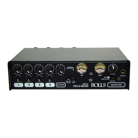
The MX422 features two calibrated, backlit VU meters. VU (Volume Units) meter
ballistics correspond closely to how the human ear perceives loudness and pro-
vides a good visual indication of how loud a signal will be. The attack and decay
of the meter signal is 300 mS. The indicated level on the meters is referenced to
SLATE TONE AND MICROPHONE
The Slate Tone and Microphone circuit is used to notate scenes at the mixer lo-
cation. The Slate circuit uses the front panel momentary button. When this button
is pressed, a 20Hz tone is sent to the Main Outputs, and the Slate Microphone
becomes active. When notating a scene - press and hold the Slate button, speak
into the four-holed Slate microphone, and release.
This oscillator is provided to set the gain structure between the MX422 and the
next device in your signal chain. The Tone oscillator is set to output a 1 kHz sine
wave to the Main Right and Left outputs (with the Output Level switch set in the
out or LINE position). Note this tone is also sent to the Headphone outputs when
the Headphone SOURCE button is in the MAIN position. It would be a good idea
For those familiar with ENG or field mixers, this guide highlights basic functionality to
begin operating your MX422.
To power the MX422 and get it ready for operation:
1. Insert four 9-Volt alkaline batteries into the battery compartments. Insert with the cor-
rect polarity. NOTE: Only one pair of batteries is being used at a time. The other pair is a
backup. More on that later.
2. Or, connect external DC power (the Rolls PS27) 12 VDC to the MX422 DC Input con-
3. Press in the POWER button.
4. Check battery life by pressing the BATT button.
To set up a gain level for an input channel:
1. Connect a signal source (microphone or line level signal) to a channel input connector.
2. Set the rear panel trim control at the 12 O’clock position (this is just a starting point).
3. If you’re using a condenser microphone, activate the Phantom Power by pressing in
4. Set the LEVEL Control at the 12 O’clock position (again - just a starting point).
5. Set the channel PAN control for the desired signal position in the stereo field.
6. Press in the rear panel “low cut” switch if needed.
7. Verify there is signal present on the output meter(s).
To connect to the MX422 main Outputs
1. Connect an XLR cable to the LEFT and RIGHT Outputs of the MX422.
2. Set the output level switch to either LINE (switch out), or -30 dB (switch in).
3. Verify that the next device in the signal chain is receiving signal from the MX422.
1. Connect stereo headphones or earphones to the HEADPHONE outputs on the front
panel. NOTE: THESE MUST BE STEREO HEADPHONES OR EARPHONES - USING
MONO PHONES WILL DAMAGE THE MX422.
2. Select the Phones signal SOURCE (monitor either the Main signal; switch out, or Moni-
3. Set the PHONES level to 0.
4. Verify signal in the phones by slowly bringing up the PHONES level control.
5. Set the PHONES level control for a comfortable level.
1. View the Main RIGHT and LEFT output signal levels on the ref. +4 dB VU meters.
2. To check the available battery voltage - press the BATT TEST button.
1. For no limiting at all, turn the LIMITER THRESH control completely clockwise.
2. To set a limiting point, send signal through the MX422 and slowly turn the LIMITER
THRESH control counter-clockwise until the desired amount of limiting is acheived.

