RollSeal RS-600M User manual

4801-9003U 1
RS-600M Intrinsically Safe Barrier Door
Installation and Operation Manual

RS-600M Intrinsically Safe Barrier Door Installation and Operation Manual
2
Section 1: Introduction.....................................................................................................................................
Section 1.1: Safety............................................................................................................................................................................
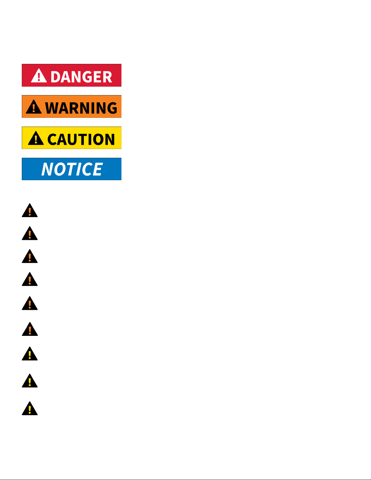
Section 1.1.1: Definitions of Signal Words and Symbols....................................................................................................................
Section 1.1.2: Statements....................................................................................................................................................................
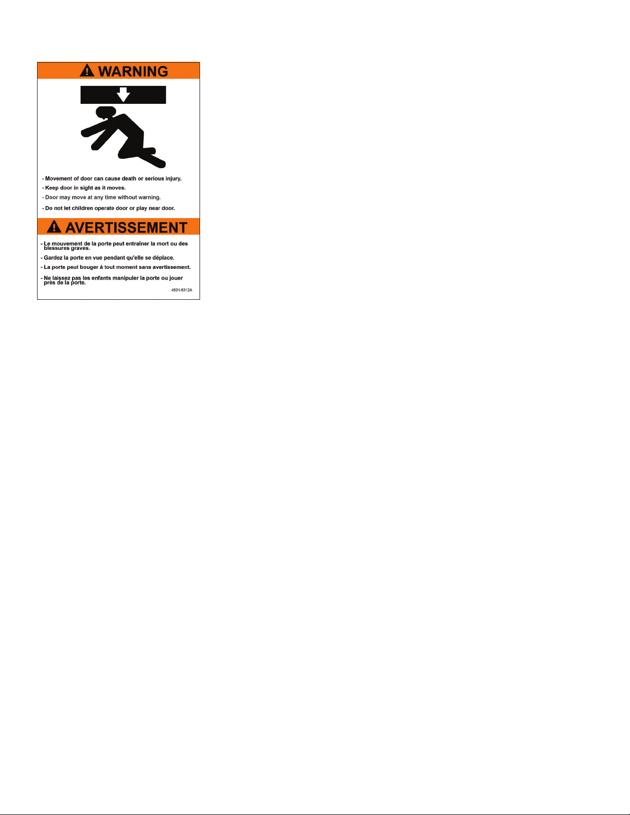
Section 1.1.3: Product Labels..............................................................................................................................................................
Section 1.2: Limited Warranty..........................................................................................................................................................
Section 1.3: Overview.......................................................................................................................................................................
Section 1.4: Dimensions...................................................................................................................................................................
Section 1.4.1: RS-600M ISB Door..........................................................................................................................................................
Section 1.4.2: SC-650M ISB Smart Controller......................................................................................................................................
Section 2: Installation.......................................................................................................................................
Section 2.1: Scope of Work...............................................................................................................................................................
Section 2.2: Adjust Framing and/or Clear Opening.........................................................................................................................
Section 2.3: Splice Tracks (if Taller Than 13')..................................................................................................................................
Section 2.4: Connect Tracks to Head Unit.......................................................................................................................................
Section 2.5: Mount Door to Clear Opening......................................................................................................................................
Section 2.6: Mount and Wire Smart Controller................................................................................................................................
Section 2.7: Mount and Wire Switches............................................................................................................................................
Section 2.7.1: One Wall (Standard).....................................................................................................................................................
Section 2.7.2: Two Parallel Walls Separated by Void.........................................................................................................................
Section 2.7.3: Two Perpendicular Walls with Bridge Plenum............................................................................................................
Section 2.8: Connect Infrared Safety Beam System........................................................................................................................
Section 2.8.1: Connect Extension Harness (if Door is Taller and/or Wider than 15')........................................................................
Section 2.9: Power............................................................................................................................................................................
Section 2.10: Install Motor Crank Handle........................................................................................................................................
Section 2.11: Prepare for Operation................................................................................................................................................
Section 3: Operation.........................................................................................................................................
Section 3.1: Switches and Smart Controller....................................................................................................................................
Section 3.2: Home Sensor and Leading Edge Switch......................................................................................................................
Section 3.3: Infrared Safety Beam....................................................................................................................................................
Section 3.4: Electrical Disconnect....................................................................................................................................................
Section 3.5: Communication Between Smart Controller and Door...............................................................................................
Section 3.6: Smart Controller User Interface..................................................................................................................................
Section 3.6.1: Overview........................................................................................................................................................................
Section 3.6.2: Display Indicator Readings..........................................................................................................................................
Section 3.7: Configuration................................................................................................................................................................
Section 3.7.1: Program Mode..............................................................................................................................................................
Section 3.7.2: Open and Close Speeds................................................................................................................................................
Section 3.7.3: Deceleration Range......................................................................................................................................................
Section 3.7.4: Open and Closed Limits................................................................................................................................................
Section 3.8: Jog Mode......................................................................................................................................................................
Section 3.9: Door Activation Inputs.................................................................................................................................................
Section 3.9.1: Directional Switch.........................................................................................................................................................
Section 3.9.2: Manual Switch..............................................................................................................................................................
Section 3.9.3: Timed Switch................................................................................................................................................................
Section 3.10: Relay Outputs.............................................................................................................................................................
Section 4: Maintenance.....................................................................................................................................
Section 4.1: Cleaning and Adjusting Components..........................................................................................................................
Section 4.1.1: Cleaning Panels and (if Present) Window...................................................................................................................
Section 4.1.2: Adjusting Panels and Tension Pipes............................................................................................................................
Section 4.1.3: Adjusting Brake.............................................................................................................................................................
Section 4.2: Replacing Components................................................................................................................................................
Section 4.2.1: Panels............................................................................................................................................................................
Section 4.2.2: Hook-and-Loop Seal.....................................................................................................................................................
Section 5: Troubleshooting................................................................................................................................
Section 5.1: Manual Operation by Crank Handle............................................................................................................................
Section 5.2: P12 Input Status Indicators..........................................................................................................................................
Section 5.3: Error Codes and Recommended Actions....................................................................................................................
Section 5.4: Drive Board Diagnostic LEDs.......................................................................................................................................
Section 5.4.1: Door Idle........................................................................................................................................................................
Section 5.4.2: Door Moving..................................................................................................................................................................
Section 5.5: Testing Brake Relay......................................................................................................................................................
Table of Contents
4
4
4
4
5
5
6
8
8
9
10
10
11
12
13
14
15
16
16
18
20
21
22
23
24
24
25
25
26
27
27
27
28
28
29
31
31
35
36
36
36
37
37
37
37
38
39
39
39
39
41
42
42
45
46
46
47
48
49
49
49
50

4801-9003U 3
Section 6: Accessories.......................................................................................................................................
Section 6.1: Passive Infrared Motion Sensor...................................................................................................................................
Section 6.2: Wave Close Proximity Sensor.......................................................................................................................................
Section 6.3: Large Door Motion Sensor............................................................................................................................................
Section 6.4: One-button Control Station.........................................................................................................................................
Section 6.5: Two-button Control Station with Key Lock.................................................................................................................
Section 6.6: Pull-cord Switch...........................................................................................................................................................
Section 6.7: Remote Receiver and Transmitter...............................................................................................................................
Section 6.8: Auxiliary Power Supply................................................................................................................................................
Section 7: Replacement Parts............................................................................................................................
Section 7.1: General..........................................................................................................................................................................
Section 7.2: Smart Controller...........................................................................................................................................................
Section 8: Diagrams..........................................................................................................................................
Section 8.1: Door Internal Wiring.....................................................................................................................................................
Section 8.2: Smart Controller...........................................................................................................................................................
Section 8.2.1: Layout............................................................................................................................................................................
Section 8.2.2: Internal Wiring..............................................................................................................................................................
Section 8.3: Interlocking Two Doors................................................................................................................................................
Section 8.4: Connecting Two-button Switches...............................................................................................................................
Section 8.5: Connecting Other Switches.........................................................................................................................................
Section 8.6: Connecting Remote Receiver.......................................................................................................................................
Section 8.7: Connecting Large Door Motion Sensor.......................................................................................................................
Table of Contents
51
51
51
51
51
51
51
51
51
52
52
54
55
55
56
56
57
58
59
60
61
62

RS-600M Intrinsically Safe Barrier Door Installation and Operation Manual
4
Section 1.1: Safety
Section 1: Introduction
All wiring must be in accordance with national electrical codes as well as any applicable local codes.
The drive is intended for incorporation into electrical control systems or machines. The installer must ensure the drive
is installed safely and in accordance with any regulations which apply to the end product at the place of use (e.g., safety
or electromagnetic compatibility). To ensure mechanical safety, additional safety devices such as electromechanical
interlocks may be required.
Disconnect all power sources before installing or performing maintenance on this equipment.
Impact with the moving door may result in death or serious injury.
The door assembly contains dangerous rotating machinery. Keep hands, clothing, etc., clear during operation. Do not
operate the door unless all guards and covers are in place.
The installer is responsible for complying with all relevant regulations (e.g., wiring and accident prevention). Particular
attention must be paid to the cross-sectional areas of conductors, the selection of fuses and other electrical protection,
and the use of protective ground/earth connections.
California Proposition 65 Warning: This product can expose you to chemicals, including lead, which is known to the State
of California to cause cancer or birth defects or other reproductive harm. For more information, go to
www.p65warnings.ca.gov/furniture.
Only qualified personnel familiar with the construction and operation of this equipment and the hazards involved are to
install, adjust, and/or service this equipment.
Section 1.1.2: Statements
The voltages in the power cables and certain parts of the drive may result in death or serious injury. If the drive has been
used, it must be isolated for five minutes before any work commences.
Section 1.1.1: Definitions of Signal Words and Symbols
This indicates a hazard that, if not avoided, could result in minor or moderate injury.
This indicates a hazard that, if not avoided, will result in death or serious injury.
This indicates important information that is not related to hazards.
This indicates a hazard that, if not avoided, could result in death or serious injury.

4801-9003U 5
Section 1.1.3: Product Labels
Label 4501-6312 indicates the moving door can cause death or serious injury. Two copies
are applied to the door. One is located inside the door opening; the other is located
outside the door opening.
Section 1.2: Limited Warranty
RollSeal, a division of HH Technologies, Inc., warrants the RollSeal Door ("the Product") to be free from defects in material and/or
workmanship for a period of either (a) one year from the date of invoice or (b) 100,000 cycles, whichever comes first, provided the
Product is installed and used in strict accordance with oicial documentation. Liability is limited to the sale price of the Product
or, at RollSeal's discretion, to the replacement of the Product upon its return.
This Limited Warranty excludes any labor, equipment, transportation, and/or service expenses that may be required to remedy the
warranted defect(s); all such charges must be funded by the purchaser. Neither the Product nor any of its component parts are to
be returned for repair or replacement until they have been inspected and/or a Return Goods Authorization (RGA) number has been
issued.
Complaints are to be directed first to the authorized distributor who sold the Product. If satisfaction is not obtained and/or the
distributor cannot be contacted, contact the Warrantor listed below, directed to the attention of "Customer Service Manager".
This Limited Warranty is void if (a) the Product and/or any of its component parts are found to have been misused, abused, or
otherwise tampered with by unqualified personnel; (b) any of the Product's component parts have been replaced by anything
other than authorized RollSeal replacement parts; (c) the Product has been modified in any way other than oicially sanctioned
upgrades made by qualified personnel using authorized RollSeal accessories; (d) the Product has not been appropriately
registered by its original purchaser; and/or (e) the customer cannot provide proof of purchase indicating them to be the Product's
original owner.
This Limited Warranty is made solely to the original purchaser of the Product. It cannot be transferred.
This Limited Warranty is in lieu of any and all other representations and/or warranties, expressed or implied, including any implied
warranty of merchantability and/or fitness for a particular purpose. The remedy set forth by this Limited Warranty shall be the
exclusive remedy available to any entity. No entity has the authority to bind RollSeal to any representation or warranty other
than this Limited Warranty. RollSeal shall not be liable for any damages or losses resulting from any application of the Product or
caused by any defect, failure, or malfunction of the Product.
This Limited Warranty gives you specific legal rights. You may have additional rights, as some areas do not allow the exclusion or
limitation of incidental or consequential damages. The above limitation or exclusion may therefore not apply to you.
Warrantor: HH Technologies (d.b.a. RollSeal)
Address: 1733 County Road 68; Bremen, AL 35033
Phone: 256-287-7000
Email: customerservic[email protected]

RS-600M Intrinsically Safe Barrier Door Installation and Operation Manual
6
Section 1.3: Overview
The SC-650M ISB Smart Controller is manufactured specifically for the RollSeal automated door. It uses internal safety devices,
in conjunction with components of the door assembly, to open and close the door automatically. The Smart Controller can also
manage the opening and closing speeds of the door, count the number of cycles the door has performed, and provide status
information for remotely monitoring the door's position. Furthermore, the Smart Controller can incorporate several auxiliary
devices to improve the operation of the door; the bottom of the enclosure has dimples to help drill holes for additional inputs.
1. Integrated sensors can detect the presence of personnel and/or machinery requiring passage through the door.
2. Integrated auxiliary lights and/or audible alarms can be used to indicate the opening or closing of the door.
3. Auxiliary inputs (sold separately) can operate the door remotely. See Section 6 for details.
Technical Specifications
Door Type D6 (RS-600M ISB)
Application Hazardous/Classified Locations
Operational Temperature Range 33°F to 200°F (0.6°C to 93.3°C)
Operational Dierential Pressure ± 0.15 inH2O
Maximum Dierential Pressure ± 0.25 inH2O
Seal Type Industrial Hook-and-Loop
Drive Type Right-angle Gear Head
Drive Mounting Side* Le of Head Unit
Speed
Up to 12’ Wide: 48” per Second
12’ to 17’ Wide: 36” per Second
17’ to 24’ Wide: 24” per Second
Input Voltage 230V
Input Current 8A
Motor Frequency 50 Hz or 60 Hz
Motor Phase 1 PH
Manual Override Crank Handle
Horsepower 1/2 HP
Brake Mechanical
Frame Material G90 Galvanized
Tension Pipe Material G90 Galvanized
Panel Material Anti-static
Standard Switch (Not Included)†2-position (Open/Close)
Certifications UL 121201
UL 325 (Class I, Division 2 — Groups A, B, C, and D)
T-Code T4
*Contact RollSeal for additional drive mounting options.
†Contact RollSeal for additional activation options.

4801-9003U 7
Substances Substance
Class
Area Classification Classification
Covered by
UL Listing
Hazardous Location Characteristics
NEC 500 NEC 505
Gases/Vapors Class I
(NEC 501)
Division 1 Zone 0 No
Explosion hazard is present continuously
or occasionally under normal operating
conditions.
Zone 1
Division 2 Zone 2 Yes (Section 1.4.1)
Ignitable concentrations of flammable
gases or vapors are not normally present,
but could be present in the event of a fault.
Dusts Class II
(NEC 502)
Division 1 Zone 20 No
Combustible dust is present in quantities
suicient to produce explosive or ignitable
mixtures.
Zone 21
Division 2 Zone 22 Yes (Section 1.4.1)
Combustible dust due to abnormal
operations may be present in quantities
suicient to produce explosive or ignitable
mixtures.
Fibers Class II
(NEC 502)
Division 1 No
Equivalent
Yes (Section 1.4.1) Easily ignitable fibers/flyings are handled
or manufactured.
Division 2 Yes (Section 1.4.1) Easily ignitable fibers/flyings are stored or
handled.
Installation Requirements
Door Size Personnel Equipment Tools Time
Up to 6’ W x 9’ H 2 Ladder Basic Hand Tools and 1” Hole Saw ~ 2 Hours
Up to 12’ W x 12’ H 3 Ladder, Forkli, and Scissor Li Basic Hand Tools, Reciprocating
Saw, and 1” Hole Saw
~ 4 Hours
Up to 24’ W x 24’ H 4 Ladder, Forkli, and 2 Scissor Lis ~ 6 Hours

RS-600M Intrinsically Safe Barrier Door Installation and Operation Manual
8
Section 1.4: Dimensions
Section 1.4.1: RS-600M ISB Door
Components within the dashed box are located inside a Class I, Division 2 hazardous
area. Mechanical switches in the hazardous area are considered a simple apparatus and
are investigated as part of the overhead door system.

4801-9003U 9
Section 1.4.2: SC-650M ISB Smart Controller

RS-600M Intrinsically Safe Barrier Door Installation and Operation Manual
10
Section 2: Installation
Section 2.1: Scope of Work
The installer is responsible for the following:
• Adjust the framing and/or clear opening (Section 2.2).
• Assemble the door frame (Section 2.4).
• Mount the door to the clear opening (Section 2.5).
• Install the Smart Controller (Section 2.6).
• Install the interior and exterior switches (Section 2.7).
• Install the externally mounted infrared safety beam system (Section 2.8).
• Set up and program the door (Section 2.11).
The electrician is responsible for the following:
• Supply permanent power to the Smart Controller (Section 2.9).
• Install and wire any additional activation devices such as remote controls, Wave Switches, and motion sensors (Section 8).
Before beginning the procedure, read this document in its entirety and inspect the
contents of the shipping crate. If any components are damaged, loose, or missing,
contact your RollSeal distributor immediately.
This document is subject to change without notice. The latest version is maintained at
rollseal.net/rollseal-technicals/.
If you require assistance during any part of the procedure, contact RollSeal Technical
Support at 1-800-668-2815.

4801-9003U 11
Section 2.2: Adjust Framing and/or Clear Opening
1. Using the diagram in Section 1.4.1, determine the required width and height of the clear opening. If necessary, adjust the
dimensions of the mounting posts and/or framing members to suit the dimensions of the door.
2. The framing material must provide adequate support for screws. Ensure the mounting posts and/or framing members are
positioned so the screw holes in the outer flanges of the vertical tracks will align with them.
3. Ensure there is adequate space for the motor and Smart Controller.
4. Allow at least 12" (ideally 18") of clearance above the head unit.
5. Allow at least 6" of clearance on the outside of each vertical track.
6. Ensure the top screw holes in the head unit will overlap and fit flush with the framing.
7. Ensure the screw holes in the vertical tracks align with the framing. The predrilled screw holes in the inner and outer flanges
will serve as attachment points when the assembly is mounted.

RS-600M Intrinsically Safe Barrier Door Installation and Operation Manual
12
Section 2.3: Splice Tracks (if Taller Than 13')
Tracks taller than 13' must be spliced as follows:
1. Slide the bottom track into the top track.
2. Align the bolt holes in the splice brackets with the bolt holes in the tracks.
3. Fasten the tracks and the splice brackets together using the included blind-head bolts and 1/4"-20 finish nuts.
Front
Back
Before Aer

4801-9003U 13
Section 2.4: Connect Tracks to Head Unit
Each end of the head unit has a U-shaped plate that fits the corresponding track. The plate has four bolt holes (two on the outside
and two on the inside) that match the bolt holes in the tracks.
1. Arrange the head unit and both tracks on the floor, face-down in front of the clear opening.
2. Align each track with the plate at the corresponding end of the head unit.
3. Slide each track onto the outside of the plate.
4. Insert the bolts through the bolt holes, then install the nuts.

RS-600M Intrinsically Safe Barrier Door Installation and Operation Manual
14
Section 2.5: Mount Door to Clear Opening
1. Center the door assembly in front of the clear opening. Align the bottom of each track with the corresponding framing
member or post.
2. Ensure the assembly is square and level.
3. Position all workers, forklis, etc., on each side of the assembly.
4. Lean the assembly upright against the clear opening.
5. Carefully press the flanges flush against the framing members or posts.
6. Secure the door assembly by installing the provided hex-drive rivets through the prepunched holes at the corners. For
all other prepunched holes, if mounting the assembly to metal, use the provided self-tapping screws or stitch screws. If
mounting the assembly to wood, use wood screws (not provided).
7. If installing the door for an insulated panel application without wood or metal backing, install the provided anchors on the
corners of the head unit and the top and bottom of the track flanges.
8. Drill a 1/4" hole in each of the two floor mounting holes at the bottom of the le track, then install the provided concrete
anchors. Repeat this step on the right track.

4801-9003U 15
Section 2.6: Mount and Wire Smart Controller
1. Using four screws, mount the Smart Controller outside the 3' classified area.
Each CPC has a key to prevent the pins from being pushed out or damaged if the CPC is
inserted incorrectly. Ensure the key is aligned before applying pressure. Once the pins
are engaged, twist the threaded rings to lock the CPC in place.
2. Ensure the Smart Controller is not connected to power.
3. Plug the circular plastic connectors (CPCs) from the AC and DC harnesses (located at the bottom of the enclosure on the right
side of the head unit) into the receptacles on the bottom of the controller.
The provided cable is long enough for the Smart Controller to be mounted up to 15'
from the head unit.

RS-600M Intrinsically Safe Barrier Door Installation and Operation Manual
16
Section 2.7: Mount and Wire Switches
The following process varies based on whether the switches are installed through a single wall (Section 2.7.1); through two parallel
walls with an intervening void (Section 2.7.2); or through two perpendicular walls with a bridge plenum (Section 2.7.3).
Section 2.7.1: One Wall (Standard)
1. Mount the outside switch in the desired location 42" above the floor.
2. Route the outside switch harness along the wall and connect the CPC to the Smart Controller.
3. Drill a 1.5" hole through the wall 13.5" below the outside switch.
4. Mount the inside switch on the opposite side of the wall from the outside switch.
5. Route the inside switch harness through the hole, then connect the CPC to the bottom of the outside switch.
6. Install escutcheon plates on both sides of the hole you drilled in Step 3.
7. Install P-clamps on the conduit as required. Mount one near the CPC to prevent tampering.
RollSeal recommends using a prewired activation switch kit. Open and close signals are
wired through intrinsically safe barriers. Other activation devices should not be used
unless they are classified for use in the operating environment. See Section 6 for switch
wiring diagrams.
The following measurements assume the wall is 2.5" thick.

4801-9003U 17
Outside Switch Inside Switch

RS-600M Intrinsically Safe Barrier Door Installation and Operation Manual
18
Section 2.7.2: Two Parallel Walls Separated by Void
1. Mount the outside switch in the desired location 42" above the floor.
2. Drill a 2" hole through the wall 4" above the outside switch.
3. Route the outside switch harness through the hole in the wall and connect the CPC to the Smart Controller.
4. Drill a 1.5" hole 7" below the outside switch.
5. Mount the inside switch opposite the outside switch 42" above the floor.
6. Drill a 1.5" hole 7" below the inside switch.
7. Route the inside switch harness through the hole, then connect the CPC to the bottom of the outside switch.
8. Install escutcheon plates over the holes you drilled in Step 4 and Step 6.
9. Install P-clamps on the conduit as required. Mount one near the CPC to prevent tampering.
The following measurements assume the walls are 2.5" thick and separated by a 9" void.
You may need to drill another 2" hole through the booth ceiling to connect the CPC to
the Smart Controller.

4801-9003U 19
Outside Switch Inside Switch

RS-600M Intrinsically Safe Barrier Door Installation and Operation Manual
20
Section 2.7.3: Two Perpendicular Walls with Bridge Plenum
1. Mount the outside switch in the desired location 42" above the floor.
2. Route the outside switch harness to the Smart Controller and connect the CPC.
3. Mount the outside switch in the desired location 42" above the floor.
4. Route the outside switch harness to the Smart Controller and connect the CPC.
5. Drill a 1.5" hole below the outside switch.
6. Mount the inside switch 42" above the floor.
7. Drill a 1.5" hole below the inside switch.
8. Route the inside switch harness through the hole, then connect the CPC to the bottom of the outside switch.
9. Install escutcheon plates over the holes you drilled in Step 3 and Step 5.
10. Install P-clamps on the conduit as required. Mount one near the CPC to prevent tampering.
Outside Switch
Inside Switch
The holes must be at least 4" below the corresponding switches. If the switches are less
than 2' apart, the holes can be drilled lower to avoid slack in the plenum.
Table of contents
Popular Indoor Furnishing manuals by other brands

John Lewis
John Lewis Ashton High Sleeper Bed Assembly instructions

Ameriwood HOME
Ameriwood HOME 1199207PCOM Instruction booklet

Allen + Roth
Allen + Roth 1652VA-30-200 manual

Furniture of America
Furniture of America CM2906-VN Assembly instructions

Gladiator
Gladiator GATL36LLMG Assembly instructions

LV Furniture
LV Furniture BOOM 131 Assembly instruction

Wholesale Beds
Wholesale Beds Panama Assembly instructions

DIVERSIFIED WOODCRAFTS
DIVERSIFIED WOODCRAFTS ADD-A-CABINET H7 Series Assembly instructions

Cambridge Casual
Cambridge Casual IT-130277T Assembly instructions

Ubique
Ubique ZG-075-GY-GG Assembly instructions

Baumax
Baumax BALTICA 0901 Assembling Instruction

Saxby
Saxby 60895 Instruction leaflet