manuals.online logo
Brands
  1. Home
  2. •
  3. Brands
  4. •
  5. ROMANO
  6. •
  7. Automobile Accessories
  8. •
  9. ROMANO MP48 User manual

ROMANO MP48 User manual

616000008-0 Rev. 210311-0 2-10
Il presente documento non può essere riprodotto né portato a conoscenza di terzi senza autorizzazione della ditta Romano S.r.l.
This document may not be reproduced or made known to any third party without permission of the company Romano Srl
MP48
4 CYL. INJECTION CONTROL UNIT
INSTALLATION MANUAL
AVVERTENZE GENERALI/GENERAL INFORMATION

Where to install the control unit:
- LONTANO da possibili.
- FAR from any WATER LEAKAGE
- LONTANO da(esempio collettori di scarico).
- FAR from(such as exhaust manifolds).
- LONTANO dai .
- FAR from
Fare delle buone connessioni elettriche evitando l’uso dei “RUBACORRENTE”.
Si tenga presente che la migliore connessione elettrica è la saldatura
debitamente isolata.
Create efcient electrical connections without using any “POWER TAPS”.
Properly insulated soldering is the most effective type of electrical connection.
Avvisare il cliente che in caso di rottura del fusibile dell’impianto a GAS, il Sistema ripri-
stina i collegamenti dei dispostivi a cui è collegato. Si sconsiglia
vivamente di sostituire il fusibile con un’altro di amperaggio maggiore, cio’ puo’ provo-
care danni irreparabili.
Advise the customer that if the GAS system fuse burns, the connections of the devices
to which it is connected will be restored. It is strongly recommended not to replace the
fuse with another one with a higher amperage rating since it may cause irreparable
damage.
Non aprire per nessun motivo la scatola della Centralina soprattutto con il motore in
moto o il quadro inserito, onde evitare danni irreparabili.
ROMANO declina ogni responsabilità per danni a cose e persone derivati dalla manomis-
sione del proprio dispositivo da parte di personale non autorizzato con la conseguente
perdita di GARANZIA.
Do not open the Control Unit box for any reason, especially when the engine is running or the key
is in the ignition, to avoid irreparable damage.
ROMANO will not be held responsible for damage to property or injuries to persons if
unauthorised personnel tamper with its devices; such tampering will also invalidate the
WARRANTY.
INSTALLAZIONE


INSTALLATION
INSTALLAZIONE
ERRATA

INSTALLATION
INSTALLAZIONE
ERRATA

INSTALLATION

ROMANO s.r.l.
Via Passariello n° 195
80038 Pomigliano d’Arco (NA) ITALY
Tel. (+39) 081 - 8847218 r.a. Fax (+39) 081 -
8847218
616000008-0 Rev. 210311-0
3-10
Il presente documento non può essere riprodotto né portato a conoscenza di terzi senza autorizzazione della ditta Romano S.r.l.
This document may not be reproduced or made known to any third party without permission of the company Romano Srl
616000008-0 Rev. 210311-0
4-10
Il presente documento non può essere riprodotto né portato a conoscenza di terzi senza autorizzazione della ditta Romano S.r.l.
This document may not be reproduced or made known to any third party without permission of the company Romano Srl
SCHEMA DI POSIZIONAMENTO MAP MAP POSITIONING DIAGRAM
NO



IL SENSORE

da riduttore
Sensore di pressioe
(MAP)

Pressione
PressureV
PressureV
OK

da riduttore
SENSORE IN ALTO
Pressione

olle
tt
o
ri
di
a
spi
ra
zi
on
e

olle
tt
o
ri
di
a
spi
ra
zi
on
e
NO


WATER


Regulator
compensation
Pressure sensor
(MAP)

MANIFOLD
Pressure
PressureV
PressureV
OK
Pressure sensor
(MAP)
Regulator
compensation

MANIFOLD
Pressure
I
n
ta
k
e
ma
nif
o
ld
I
n
ta
k
e
ma
nif
o
ld
1234
0
1/2
4/4
BIANCO
VERDE
BIANCO
VERDE
MASSA
MASSA
BIANCO
VERDE
BIANCO
MASSA
SENSORI STANDARD A.E.B.
TIPO 1050
SENSORI STANDARD 0÷90
OHM
VERDE NON COLLEGARE
ABCD
1 2 1 2 1 2 1 2
-
-
-
-
VERDE/NERO
VERDE
GIALLO/NERO
GIALLO
GRIGIO
VIOLA
ELETTROVALVOLA
RIDUTTORE
SENSORE DI PRESSIONE
MAP AEB 025
BLU
BLU/NERO
ROSSO/NERO
ROSSO
BLU
NERO
ROSSO/NERO
NERO
MASSA
12 12 12 12
NERO
ARANCIO
ATTENZIONE
IL CONNETTORE DELL’INIETTORE GAS
MARCATO ADEVE CORRISPONDERE AL
FILO BLU DEL CAVO STACCA INIETTORI
PRESA DIAGNOSTICA
AL SENSORE
TEMPERATURA ACQUA
12
SONDA LAMBDA
MARRONE RPM
OPZIONALE
+
ROSSO/BIANCO
+12VOLT SOTTO CHIAVE
G
R
COMMUTATORE
BIANCO/BLU
ELETTROVALVOLA
SERBATOIO
NERO
+
-
NERO
ARANCIO/NERO AL SENSORE
TEMPERATURA GAS
PressureV
1234
1234
0
1/2
4/4
WHITE
GREEN
WHITE
GREEN
GROUND
GROUND
WHITE
GREEN
WHITE
GROUND
A.E.B. STANDARD SENSORS
TYPE 1050
0÷90 OHM STANDARD
SENSORS
GREEN DO NOT CONNECT
ABCD
1 2 1 2 1 2 1 2
-
-
-
-
GREEN/BLACK
GREEN
YELLOW/BLACK
YELLOW
GREY
VIOLET
PRESSURE REGULATOR
SOLENOID VALVE
AEB 025
PRESSURE GAUGE
BLUE
BLUE/BLACK
RED/BLACK
RED
BLUE
BLACK
RED/BLACK
BLACK
GROUND
12 12 12 12
BLACK
ORANGE
ATTENTION
THE CONNECTOR OF THE GAS INJECTOR A MUST
CORRESPOND TO THE BLUE WIRE OF THE
CUT-INJECTOR CABLE
DIAGNOSTIC SOCKET
TO THE WATER
TEMPERATURE SENSOR
12
OXYGEN
SENSOR
BROWN RPM
OPTIONAL
+
RED/WHITE
+12VOLT WITH IGNITION KEY
G
R
CHANGE OVER
SWITCH
WHITE/BLUE
FUEL TANK
SOLENOID VALVE
BLACK
+
-
BLACK
ORANGE/BLACK TO THE GAS
TEMPERATURE SENSOR
PressureV
1234
616000008-0 Rev. 210311-0 9-10 616000008-0 Rev. 210311-0
10-10
Il presente documento non può essere riprodotto né portato a conoscenza di terzi senza autorizzazione della ditta Romano S.r.l.
This document may not be reproduced or made known to any third party without permission of the company Romano Srl
Il presente documento non può essere riprodotto né portato a conoscenza di terzi senza autorizzazione della ditta Romano S.r.l.
This document may not be reproduced or made known to any third party without permission of the company Romano Srl
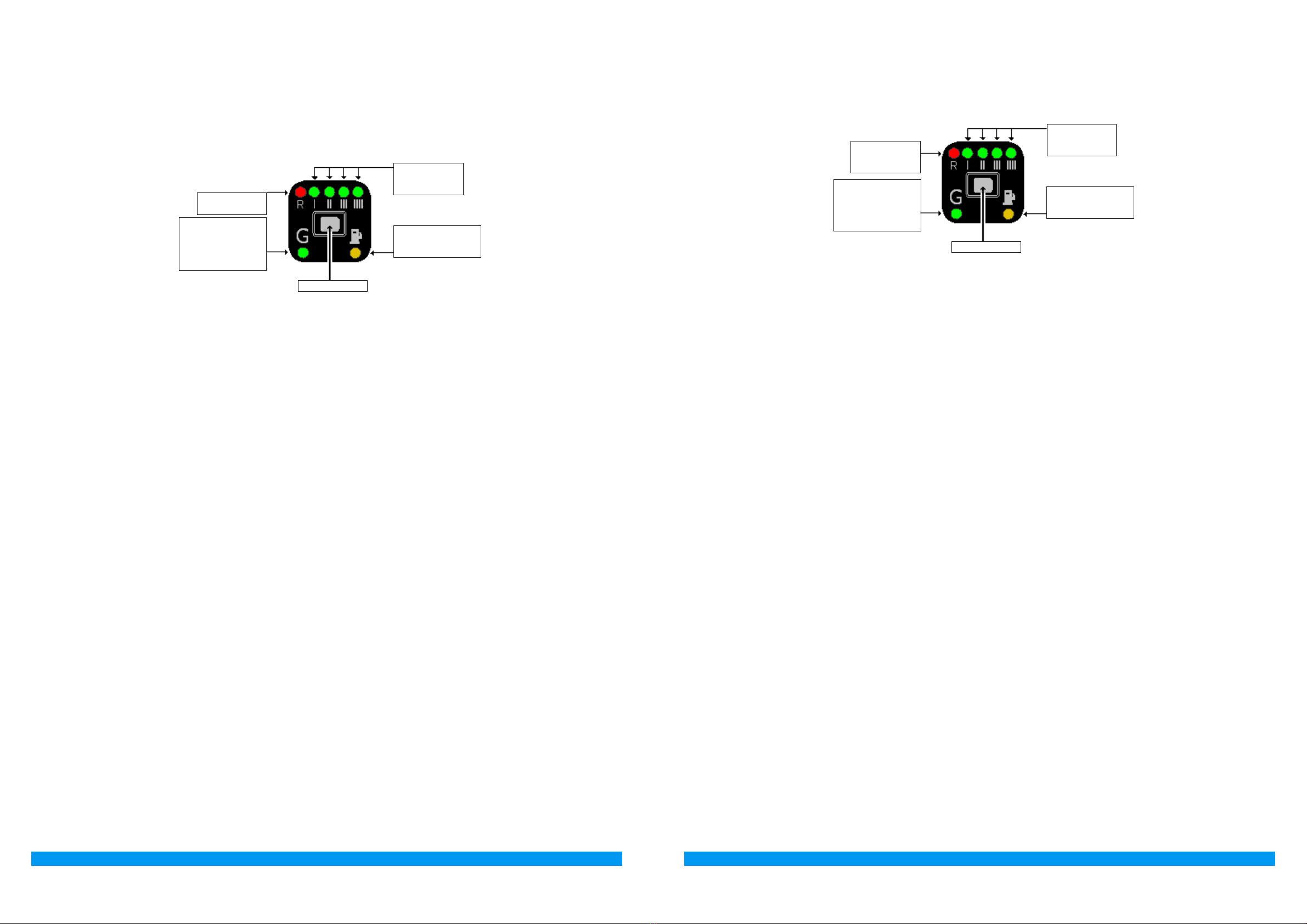
FUNZIONAMENTO DEL COMMUTATORE
Descrizione del funzionamento
Il commutatore che viene fornito nel kit dispone di un pulsante, 7 led luminosi e un cicalino in-
terno.

Serve per selezionare il tipo di alimentazione, Benzina o Gas; premendolo si passerà da un tipo di
carburante all’altro.

la centralina è predisposta per l’avviamento a Benzina
ed il passaggio automatico a GAS.
funzionamento a GAS.

Indicatore di livello carburante; led ROSSO riserva, mentre i 4 led VERDI forniscono l’indica-
zione del livello carburante (1/4, 2/4, 3/4, 4/4). L’indicatore è acceso solo quando è selezionata la
modalità gas.

funzionamento a BENZINA.
la centralina è predisposta per l’avviamento a Benzina
ed il passaggio automatico a GAS.

Quando il commutatore è in riserva e la pressione del gas scende al di sotto di un valore prestabilito,
la centralina commuta automaticamente a benzina. Questo viene fatto per evitare che il motore possa
girare con una carburazione troppo magra danneggiando così il catalizzatore. Prima di ripassare la
vettura a Gas effettuare il rifornimento.  viene
segnalato dal commutatore con l’accensione del led GIALLO funzionamento a Benzina, l’accensione
alternata del LED ROSSO indicatore e dei 4 LED VERDI e con l’avviso acustico del cicalino interno. Per
riportare il commutatore al funzionamento normale è necessario premere una volta il PULSANTE,
rimarrà acceso il LED GIALLO per indicare che la vettura sta funzionando a Benzina ed il cicalino
smette di suonare.
4 LED VERDI
LIVELLO
CARBURANTE
LED GIALLO
FUNZIONAMENTO
A BENZINA
LED ROSSO
RISERVA
PULSANTE
LED VERDE
FUNZIONAMENTO
A GAS
SEGNALAZIONE
DIAGNOSI
CHANGEOVER SWITCH OPERATION
Operating description
The changeover switch supplied with the kit has one button, 7 LEDs and an internal buzzer.

This is used to select either the petrol or the gas fuel supply. Press the button one time to switch to
gas and press it again to return to petrol.

 the control unit is prepared to start with petrol and switch automatically to GAS.
 Gas operation.

Fuel level indicator; reserve RED LED, while the 4 GREEN LEDS indicate the fuel level (1/4, 2/4,
3/4, 4/4). The indicator is illuminated only when the gas mode is selected.

PETROL operation.
the control unit is prepared to start with petrol and
switch automatically to Gas.

When the changeover switch indicates the fuel tank is in reserve and the gas pressure drops below a
set value, the control unit automatically switches over to gas. This prevents the engine from running
with an excessively lean carburetion, thus damaging the catalyser. Before returning to gas opera-
tion, ll up. The changeover switch signals the changeover to petrol due to low gas pressure by
activating the internal buzzer, illuminating the YELLOW petrol operation LED and by illuminating the
RED LED in an alternating pattern with the 4 GREEN LEDS. To make the changeover switch return to
normal operation press the BUTTON one time; the YELLOW LED will remain on to indicate that the
car is operating with petrol and the buzzer turns off.
4 GREEN
LEDS - FUEL
LEVEL
YELLOW LED -
PETROL
OPERATION
RED LED –
EMPTY TANK
RESERVE
BUTTON
GREEN LED -
GAS OPERATION
WITH
DIAGNOSTIC
SIGNAL

Popular Automobile Accessories manuals by other brands

GReddy Intercooler Kit installation manual

GReddy

GReddy Intercooler Kit installation manual

Metra Electronics 99-7860 installation instructions

Metra Electronics

Metra Electronics 99-7860 installation instructions

Thule SPIRIT 780 manual

Thule

Thule SPIRIT 780 manual

Metra Electronics 99-7423 installation instructions

Metra Electronics

Metra Electronics 99-7423 installation instructions

Dynojet POWER COMMANDER III USB EX installation instructions

Dynojet

Dynojet POWER COMMANDER III USB EX installation instructions

Rand McNally OverDryve Pro user guide

Rand McNally

Rand McNally OverDryve Pro user guide

HAUL MASTER 34313 Assembly and operating instructions

HAUL MASTER

HAUL MASTER 34313 Assembly and operating instructions

SWEEX IP003 manual

SWEEX

SWEEX IP003 manual

Thule WanderWay instructions

Thule

Thule WanderWay instructions

Whelen Engineering Company SA314 installation guide

Whelen Engineering Company

Whelen Engineering Company SA314 installation guide

PAC SWI-RC installation instructions

PAC

PAC SWI-RC installation instructions

AMiO RBR-02 user manual

AMiO

AMiO RBR-02 user manual

Michelin 009559 user guide

Michelin

Michelin 009559 user guide

Panasonic CQ-RX200U Service manual

Panasonic

Panasonic CQ-RX200U Service manual

HUSKY LINERS 2107 Care and use instructions

HUSKY LINERS

HUSKY LINERS 2107 Care and use instructions

HealTech Electronics SPEEDOHEALER v4 user manual

HealTech Electronics

HealTech Electronics SPEEDOHEALER v4 user manual

Metra Electronics AW-333GM installation instructions

Metra Electronics

Metra Electronics AW-333GM installation instructions

Whispbar K398W Fitting instructions

Whispbar

Whispbar K398W Fitting instructions

manuals.online logo
manuals.online logoBrands
  • About & Mission
  • Contact us
  • Privacy Policy
  • Terms and Conditions

Copyright 2025 Manuals.Online. All Rights Reserved.