RoomAndLoft Murphy User manual

8.1.22 ls
Thank you so much for your purchase!!!
If you need anything –please call us at:
714-455-7446
For Fast Service!
Watch our helpful assembly video@
WallbedGallery.com/video
Set-up Instructions for:
•Murphy Bed
•Murphy DeskBed

First –a few words of advice and caution:
1. Please do this job with two people. Attempting to do it alone, though heroic, could lead to product damage or injury
because some things might be too heavy for just one person to safely handle. With two people, the job will be much
smoother and safer –and a lot more fun!
2. Please read and follow the instructions carefully, as it will save time and avoid possible incorrect set-up of the product.
3. Please do not over-tighten screws and bolts, as it may lead to “stripping” the threads and make the connection weak. The
best rule is “firm and snug is what we need”.
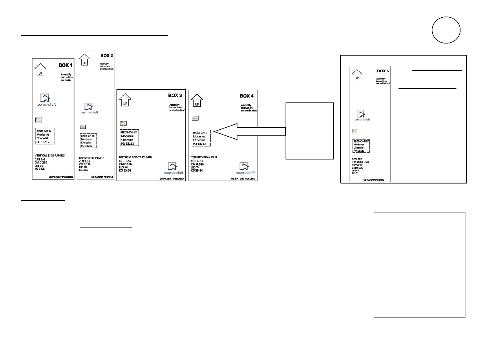
4. If you will be installing your Murphy Bed on a hard surface such as stone, hardwood floor, tile, (anything other than carpet),
please lay down enough padding to lay the parts on while assembling. This will protect the Murphy bed parts from the floor,
and vice-versa. We recommend enough blankets, comforters, etc., to cover at full10foot x 10 foot area.
5. Before you begin your installation, PLEASE take a few minutes to WATCH our helpful assembly VIDEO which is available for
viewing online at www.wallbedgallery.com/video
Note: Your ceiling height needs to be at least 91 1/2” for the Murphy Bed to be installed
Murphy Bed Set-up Guide
Congratulations and a Big Thank You for your purchase of a RoomAndLoft Murphy Bed!
We sincerely appreciate your business!
1
United States Patent Pending

PREPARATION FOR ASSEMBLY:
Please locate and confirm that you have the following 4 boxes to complete your Queen Size Murphy Bed.
PLEASE NOTE: The boxes are numbered “BOX 1” through “BOX 4”, please open the boxes as they are called for in this Set-Up Guide,
beginning with BOX 1.
TOOLS & THINGS YOU NEED TO SUPPLY:
•A power drill gun with a #2 Phillips-head drive with a short extension.
•An Electronic Stud Finder.
•A step ladder that can safely hold your feet 30” off the floor.
•A pencil.
•A Queen-size mattress that is maximum 10” thick, and weighs maximum 70 lbs.
OTHER NOTES:
Please be aware that hardware parts will appear in each box as the Assembly Project progresses.
If and when parts are left over after completing a step, please lay them aside for use in a later step!
Please sift carefully through packing materials to make sure hardware packs don’t go out in the trash.
HAVE FUN! –and call us if you need assistance at 714-455-7446.
2
Please ignore
the example
part numbers
on these boxes
as yours could
be different.
HELPFUL HINT:
Throughout the assembly of
your Murphy Bed, you will find it
helpful to refer frequently to
pages 25-28, where the contents
of each bubble pack and
hardware box are illustrated for
easy reference.
The bubble pack and hardware
box contents for the desk bed
can be found on page 31.
If you have the
Murphy DeskBed…
you will also
Have a “Box #5”.
Just follow the
Set-up Guide and
you’ll get there.

Wall
Setting up the Bed Case – part A
Step 1: Open Box #1, and lay out the top and bottom panels of the left and right side panels as shown, noting the distances marked between the panels
and from the bottom edge of the side panels to the wall.
3
K157B3/8” spacer blocks
K157A1/4” spacer blocks
K161B12mm wrench
K161A1/2” wrench
BUBBLE-PACK #1
CONTENTS
SHOWN ON
PAGE19
Guide Dowel
Top
right side
Bottom
right side
Top
left side
Bottom
left side
FROM BUBBLE PACK1 - HOLD THESE
PARTS ASIDE FOR LATER USE

K117A
Safety chain from
Box2, bubble-pack 2
K113C
Bolts
K160
Allen wrench
K123
screw s
Wall
Step 2: Align the top and bottom side panels with the guide dowels, then connect by using K113C bolts through the metal plate into imbedded sleeves.
Step 3: Open Box #2 and find bubble pack 2. Install the safety chains on both size panels using K123 screws.
4
Step 2
Step 3

K111
nut
K110
bolt
K160
Allen wrench
Top panel
Setting up the Bed Case – part B
Step 1: Open Box #2. Place the top panel on edge with the face molding toward the floor as shown. Gently roll the side panels up and slide the molding underneath, using guide
dowels to position the panels together. Use a K110 bolt and K111 barrel nut at each corner to connect the top panel to the sides as shown.
5
Roll up
Roll up
BUBBLE-PACK #2 CONTENTS
SHOWN ON PAGE 26
dowel

K160
Allen wrench
K110
bolt
K111
nut
TOP PANEL
TOP BACK PANEL
Step 2: Position the top-back panel and connect with K110 bolts and K111 barrel nuts as shown.
6
TOP PANEL
TOP BACK
PANEL

Setting up the Bed Case – part C
Step 1: From Box 2, find the Headboard panel and position the headboard to the side panels using guide dowels.
Step 2: Use K110 bolts and K111 barrel nuts from bubble pack 2 to connect the headboard to the side panels.
7
Headboard
Zip line face down
away from the wall
Headboard
BACK
K160
Allen
wrench
K110
bolt
K111
nut
Step 1
Step 2
Headboard
FRONT
dowel

Quarter-round molding
must be removed
Base molding up to 5” tall and
5/8” thick can stay
Chair-rail molding
must be removed
FLOOR
WALL
To setup the Murphybed
The chair rail.and the
Quarter-round molding
must be removed
To set up your Murphy Bed,
any quarter-round molding,
and any chair rail must be
removed before installing the
bed case. The base molding
can usually be left in place.
Step 1
Step 2
Quarter-round
molding
Chair-rail
molding
base
molding
WALL
Preparing the wall for the Murphy-bed Case
Step 1: Identify the exact position you would like to set up your Murphy bed, and check the position of the nearby electrical outlets, if any.
DANGER: Any electrical outlet must be at least 5” away in either direction from both of the Bed Case side panels.
Step 2: Once you have Identified the correct position to stand up the Bed Case, remove any chair rail and/or quarter round molding if any for a width of 65” to
accommodate the 64.3/4” wide Bed Case.
8
YOU CAN LEAVE THE BASE MOLDING ALONE
IF IT IS 5/8” X 5” OR LESS

WALL
FLOOR
PLEASE LIFT!
(DO NOT DRAG)
GRAB CORNERS
1 CORNER PER PERSON
Standing up the Bed Case
Step 1: With two people, take hold of the
top corners of the bed case and safely lift to
stand up the Bed Case.
Step 2: Position the bed case against the wall by lifting and carrying
– PLEASE do not drag the bed case on the floor.
Step 3: Check the exterior measurement of the Bed Case side panels at the floor, and make
sure it measures 64.3/4 inches, no more, no less.
9

PREPARING TO ATTACH THE BEDCASE TO THE WALL
5
8" Thick
base molding
1
2" Thick
base molding NO
base molding Removing plastic
industrial cope
WALL
WALL
WALLWALL
WALL
WALL
base molding
FOOTER STUD
INSIDE THE
WALL DRIVE SCREWS
A 10 DEGREE
DOWN-ANGLE
No
Spacer block
1/4”
Spacer block
Use one of
each size
spacer blocks
Follow #3
AFTER
removing
the plastic
industrial
cope.
①
②
③
④
HOW TO USE SPACER BLOCKS – IF NEEDED
IF YOUR BASE MOLDING IS SOLID WOOD …..
PLEASE USE A 1/8” DRILL BIT TO PRE-DRILL
THROUGH THE BASE MOLDING ONLY (NOT BASE
PLATE) TO REDUCE THE CHANCE OF SPLITTING
YOUR BEAUTIFUL WOOD MOLDING
Top plate
Wall stud
“Bottom plate”, “Base plate”, “sole
plate”, are all names for this 2x4
that runs across the floor at the
bottom of a wall.
Electric plug socket
(see page 6
for electrical
Outlet avoidance)
A QUICK PRIMER ON WOOD-FRAMED HOMES.
OUR TARGET IS THE BASE PLATE
BASEPLATE
10
HELPFUL HINT
If your wall is brick or
concrete block (not built
with a wooden frame and
drywall) please refer to
page 33 for more
information about
installation into non-
wooden structures.

STEP 2:
MEASURE THE OUTSIDE
DIMENSION AT THE FLOOR
AND MAKE SURE IT IS 64 3/4”
STEP 3:
USING SPACER BLOCKS IF
REQUIRED AS SHOWN ON PAGE 10, USE
YOUR DRILL-GUN WITH A #2 PHILLIPS
HEAD TO DRIVE K119 SCREWS AT A 10
DEGREE DOWN-ANGLE TO ATTACH
METAL FRAME TO THE WALL (DIAGRAM
ON PAGE 10).
STEP 1:
USE A PENCIL AND STUD-FINDER
TO MARK THE CENTER OF A
STUD ON EACH SIDE. THE STUD
PLACEMENT DOES NOT NEED TO
BE LATERALLY SYMMETRICAL.
(WE WILL USE THESE MARKS IN A
LATER STEP.)
STEP 1
USE A STEP LADDERTHAT WILL
SAFELY ALLOW YOU TO
MEASURESTUD POSITIONS
Marking Studs, measuring width one last time,
and driving long screws into the base plate.
11
Measure again.
Drive K119 screws
STEP 2
STEP3

Setting up the Bed Tray
BT
BOTTOM TRAY
TT
TOP TRAY
K152
Side connector bar
K153
2 Bayonet connect bar
K152
Side connector bar
K152
Side connector bar
K152
Side connector bar
Make sure the
Bearing Post is
positioned
toward the Bed
Case
Place open area of BT tray
toward the Bed Case.
FROM BOX #3
FROM BOX #4
Open boxes #3 and #4 and lay out the contents as shown below with the wood face of the bed tray face-down on the carpet/blankets/etc., that will protect it.
Pay find and lay out the K153 Bayonet Connectors and the K152 Side Connector Bars that you will find distributed in the two boxes.
12
HARDWARE BOX #3 & BUBBLE-PACK #3
CONTENTS SHOWN ON PAGE 27
HARDWARE BOX #4 & BUBBLE-PACK #4
CONTENTS SHOWN ON PAGE 28

TT
TOP TRAY
K153 bayonet
connector
bars
Insert K105B bolts with K106
fender washers, but leave them
loose so there is some “play”
K161B Wrench
K105B Bolt
K106 Fender washer
TT
TOP TRAY
K153 bayonet connector bar
from boxes #3& #4
K161B Wrench
K106 Fender washer
K105B Bolt
WOOD TRAY FACE
Insert bayonets with the short “leg”
oriented up as shown
K153 bayonet
connector
bars
(FROM BUBBLE PACK #3)
Welded Nut
Connecting the Top Tray (TT) to the Bottom Tray (BT).
Step 1: Insert the K153 Bayonet ABOUT HALFWAY into the TT tray as shown below – with the short leg of the “L” shape “up” as in the
drawing at the bottom left of this page - then hand start the bolts and leave them loose for now.
13
SEE FROME TOP SIDE

K106 Fender washer
INSERT BOLTS AND
WASHERS. START BY
HAND AND LEAVE
THEM LOOSE SO
THERE IS SOME
“PLAY”
K105B Bolt
TT
TOP TRAY
BT
BOTTOM TRAY
Step 2: Now insert the bayonets into the BT tray and slide the two trays together. Again, hand start the bolts but leave them loose.
14

STEP 1
Install 4 K105B bolt
+4 K106 washer
and tighten fully
STEP2
Fully tighten all 6
bayonet bolts
K105B bolt
K106 washer
K161B
Connecting all the Supports to build a strong frame
Step 1: Use 4 K015B Bolts with 4 K106 Washers, and the K161B wrench to tightly connect the lateral-center frames of TT to BT.
Step 2: Now go back and fully tighten the 6 bolts that we left loosely connected through the bayonets on the previous page.
15

Connect 4 K152
connector bar
as shown
K105B bolt
K106 washer
K152 connector bar
Wood
face
K161B
wrench
Upper capture
Lower
capture
Make sure bar is fully
between all 4 upper and
lower captures
Step 3: One-at-a-time, position the 4 K152 support bars – making sure they are nestled between all 4 upper and lower captures - and install
with 4 bolts and 4 washers each, and tight fully.
16
K105B bolt
K106 washer
K152 connector bar
K152 connector bar
K152 connector bar
K152 connector bar

K154
mattress hoop
STEP 1: INSTALL MATTRESS HOOPS INTO THE PROVIDED HOLES
This edge toward
the mattress
STEP 2: ATTACH A GAS SPRING AS SHOWN TO EACH SIDE USING K143 LOCK NUT.
HAND TIGHTEN ONLY - YOU WILL TIGHTEN FULLY LATER.
Installing Mattress Hoops and Gas Springs
17
HELPFUL HINT: The mattress hoops are found in the Hardware package inside Box #3
K143
Lock Nut
Gas spring
Gas Spring
STEP 2:
Install the handles and screws from Hardware box 4 through the
pre-drilled holes on the wooden tray faces.
K118B
Handle
screw
K118B
MDH

Lifting the Bed Tray Bearing Posts into the Saddles, and installing the Pivot top Capture
BED TRAY
BED CASE
Saddle
Bearing
post
Equal gap both sides
Saddle
Bearing capture K158
Saddle
K138
Sheet metal screw
18
Step 1: With one person on each side of the bed about in the middle, carefully lift the bed tray and set the Bearing posts into the saddle on each side of the bed.
Make sure the bearing post gap is equal on each side. The key thing here is to take your time and get lined up right so you can limit the possibility of damaging
the wood Bed Tray Face or the interior finish of the Bed Case.
Step 2: Once both bearing posts are in the saddles, install the K158 bearing capture using the K138 screws.
Step 3: Prop up the foot end of the bed with some pillows or something and install the handles.
Step 1:Two people carefully lift
the bed tray so that the bearing posts
rest in the saddles on both sides.
Result of Step 1
Step 2
Bearing post
STEP 3: Install the handles and screws from
Hardware box 4 through the pre-drilled holes on the
wooden tray faces.

Complete the connection of the Gas Springs
USE 2 PEOPLE AS SHOWN!
K143
Lock Nut
Gas spring
K143
Lock Nut
Gas
spring
19
STEP 1:
A) Attach one of the safety chains
B) Slightly over-rotate the bed tray into the bed case about 3” to 4” to allow the bottom
gas spring head to align with the spring attachment post on the metal bed frame.
STEP 2:
Reach under the bed tray and through the open space at the bottom of the bed tray to fit the bottom
gas spring head to the gas spring attachment post. Install the K143 lock nut to each post and snug it
up with the K161A wrench.
C)
D)
SAFETY WARNING!
The purpose of the Gas Spring is to “counter-balance” the weight of the mattress by applying upward force, and thereby
making the bed tray “feel lighter” when you lift it to close the bed. It is IMPERATIVE that you follow the instructions PAGE 22
OF STEP 4 carefully, and that you NEVER remove or change the mattress without two people – one of whom will hold the bed
tray down whenever the mattress is removed. FAILURE TO HEED THIS WARNING CAN RESULT IN PRODUCT DAMAGE
AND/OR INJURY!
PERSON A
PERSON B
PERSON B VIEW
FRONT VIEW
Table of contents
Other RoomAndLoft Indoor Furnishing manuals
Popular Indoor Furnishing manuals by other brands

Regency
Regency LWMS3015 Assembly instructions

Furniture of America
Furniture of America CM7751C Assembly instructions

Safavieh Furniture
Safavieh Furniture Estella CNS5731 manual

PLACES OF STYLE
PLACES OF STYLE Ovalfuss Assembly instruction

Trasman
Trasman 1138 Bo1 Assembly manual

Costway
Costway JV10856 manual