TABLE OF CONTENTS
Introduction........................................................................................................................... 3
Warnings ................................................................................................................................ 4
Modules .................................................................................................................................. 6
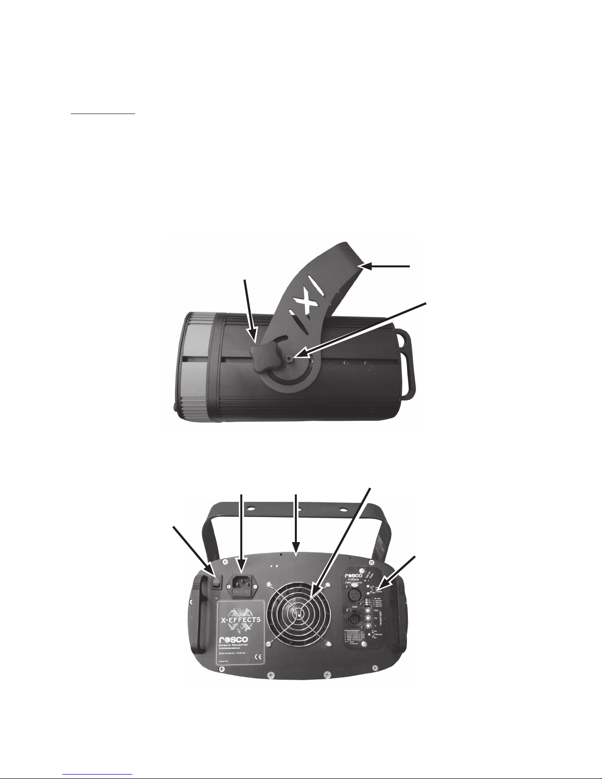
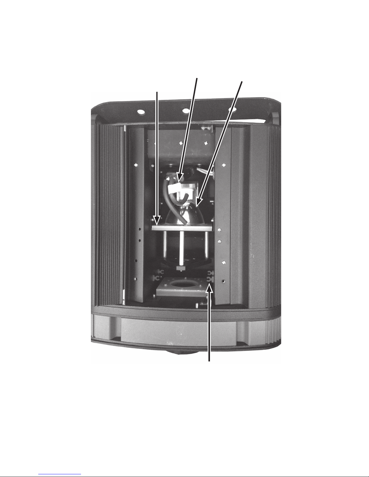
Base Unit .........................................................................................................................................................6
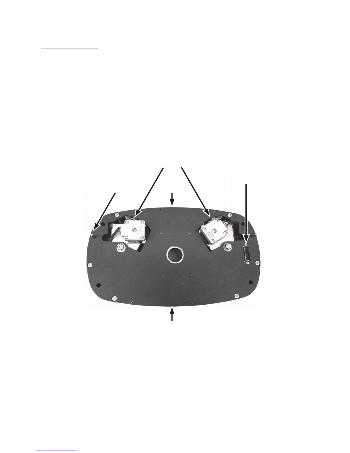
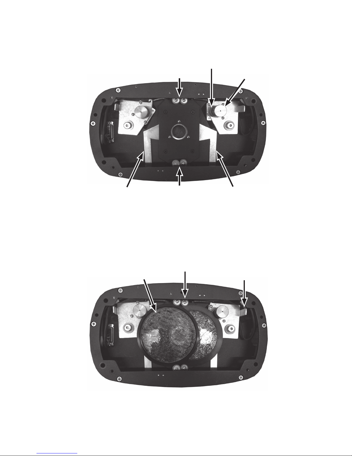
Wheel Module...............................................................................................................................................8
Lens Module ................................................................................................................................................10
Analog Control Panel................................................................................................................................11
Preparing for Use................................................................................................................. 12
Installing the Lamp (Base Unit).............................................................................................................12
Installing a Glass Pattern (Wheel Module) .......................................................................................13
Installing a Lens Barrel (Lens Accessory) ...........................................................................................14
Unit Operation (Analog,Wheel, Lens) ................................................................................ 15
Mounting .....................................................................................................................................................15
Powering Up................................................................................................................................................15
Adjusting Brightness ...............................................................................................................................16
Adjusting Focus..........................................................................................................................................16
Adjusting Wheel Speed and Direction ..............................................................................................16
Adjusting Shutters on the Wheel Module.........................................................................................16
DMX Control Module........................................................................................................... 17
Dowser...........................................................................................................................................................18
Manual Mode ..............................................................................................................................................19
DMX Mode ...................................................................................................................................................20
Troubleshooting .................................................................................................................. 22
Specifications....................................................................................................................... 24
Mechanical Specifications ......................................................................................................................24
Electrical Specifications ...........................................................................................................................24
Wheel Module Specifications................................................................................................................24
Lamp Specifications..................................................................................................................................24
Lens Module Specification .....................................................................................................................24
Warranty............................................................................................................................... 25
Certificate of Conformity .................................................................................................... 26
2X24 PROJECTOR ORIGINAL INSTRUCTIONS