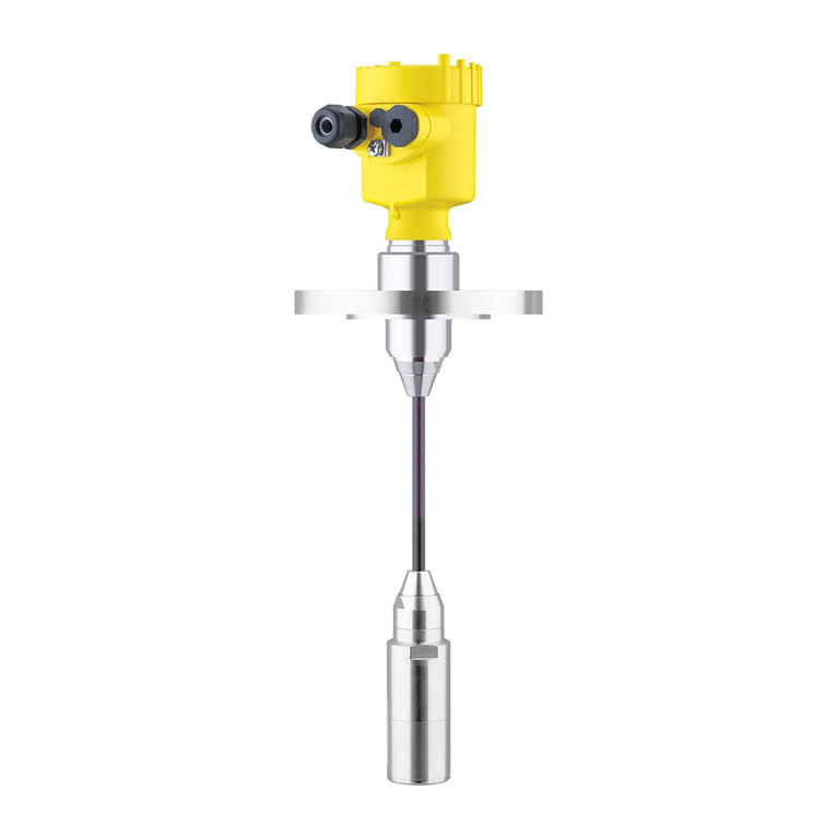
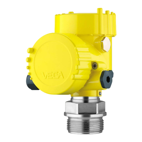
Vega VEGABAR 87 User manual

Quick setup guide
Submersible pressure transmitter with
metal measuring cell
VEGABAR 87
Modbus and Levelmaster protocol
Document ID: 46330

2
Contents
VEGABAR 87 • Modbus and Levelmaster protocol
46330-EN-190404
Contents
1 For your safety ......................................................................................................................... 3
1.1 Authorised personnel ....................................................................................................... 3
1.2 Appropriate use................................................................................................................ 3
1.3 Warning about incorrect use............................................................................................. 3
1.4 General safety instructions............................................................................................... 3
1.5 EU conformity................................................................................................................... 4
1.6 Permissible process conditions........................................................................................ 4
1.7 NAMUR recommendations .............................................................................................. 4
1.8 Environmental instructions ............................................................................................... 4
2 Product description ................................................................................................................. 5
2.1 Conguration.................................................................................................................... 5
3 Mounting................................................................................................................................... 6
3.1 General instructions for use of the instrument .................................................................. 6
3.2 Ventilation and pressure compensation............................................................................ 6
4 Connecting to power supply and bus system ...................................................................... 7
4.1 Connecting....................................................................................................................... 7
4.2 Wiring plan ....................................................................................................................... 8
5 Set up the sensor with the display and adjustment module............................................. 10
5.1 Insert display and adjustment module............................................................................ 10
5.2 Parameter adjustment - Quick setup .............................................................................. 10
5.3 Parameter adjustment - Extended adjustment................................................................ 12
5.4 Menu overview ............................................................................................................... 13
6 Supplement ............................................................................................................................ 16
6.1 Technical data ................................................................................................................ 16
Information:
This quick setup guide enables quick setup and commissioning of
your instrument.
Youcanndsupplementaryinformationinthecorresponding,more
detailed Operating Instructions Manual as well as the Safety Manual
thatcomeswithinstrumentswithSILqualication.Thesemanualsare
available in the download area of "www.vega.com".
Operating instructions VEGABAR 87 - Modbus and Levelmaster
protocol: Document-ID 46297
Editing status of the quick setup guide: 2019-04-02

3
1 For your safety
VEGABAR 87 • Modbus and Levelmaster protocol
46330-EN-190404
1 For your safety
1.1 Authorised personnel
All operations described in this documentation must be carried out
onlybytrained,qualiedpersonnelauthorisedbytheplantoperator.
Duringworkonandwiththedevice,therequiredpersonalprotective
equipment must always be worn.
1.2 Appropriate use
Model VEGABAR 87 is a pressure transmitter for level and gauge
measurement.
Youcannddetailedinformationabouttheareaofapplicationin
chapter "Product description".
Operational reliability is ensured only if the instrument is properly
usedaccordingtothespecicationsintheoperatinginstructions
manual as well as possible supplementary instructions.
1.3 Warning about incorrect use
Inappropriate or incorrect use of this product can give rise to applica-
tion-specichazards,e.g.vesseloverllthroughincorrectmounting
or adjustment. Damage to property and persons or environmental
contaminationcanresult.Also,theprotectivecharacteristicsofthe
instrument can be impaired.
1.4 General safety instructions
This is a state-of-the-art instrument complying with all prevailing
regulations and directives.The instrument must only be operated in a
technicallyawlessandreliablecondition.Theoperatorisresponsi-
ble for the trouble-free operation of the instrument.When measuring
aggressive or corrosive media that can cause a dangerous situation
iftheinstrumentmalfunctions,theoperatorhastoimplementsuitable
measures to make sure the instrument is functioning properly.
Duringtheentiredurationofuse,theuserisobligedtodeterminethe
compliance of the necessary occupational safety measures with the
current valid rules and regulations and also take note of new regula-
tions.
Thesafetyinstructionsinthisoperatinginstructionsmanual,thena-
tional installation standards as well as the valid safety regulations and
accident prevention rules must be observed by the user.
Forsafetyandwarrantyreasons,anyinvasiveworkonthedevice
beyond that described in the operating instructions manual may be
carried out only by personnel authorised by the manufacturer. Arbi-
traryconversionsormodicationsareexplicitlyforbidden.Forsafety
reasons,onlytheaccessoryspeciedbythemanufacturermustbe
used.
Toavoidanydanger,thesafetyapprovalmarkingsandsafetytipson
the device must also be observed and their meaning read in this oper-
ating instructions manual.
4
1 For your safety
VEGABAR 87 • Modbus and Levelmaster protocol
46330-EN-190404
1.5 EU conformity
ThedevicefullsthelegalrequirementsoftheapplicableEUdirec-
tives.ByaxingtheCEmarking,weconrmtheconformityofthe
instrument with these directives.
YoucanndtheEUconformitydeclarationonourwebsiteunder
www.vega.com/downloads.
1.6 Permissible process conditions
Forsafetyreasons,theinstrumentmustonlybeoperatedwithinthe
permissibleprocessconditions.Youcannddetailedinformationon
the process conditions in chapter "Technical data" as well as on the
type label.
Thepermissibleprocesspressurerangeisspeciedonthetypelabel
with"MWP"(MaximumWorkingPressure),seechapter"Congura-
tion".This applies even if a measuring cell with a measuring range
(order-related) higher than the permissible pressure range of the
processttingisinstalled.
Atemperaturederating,e.g.withanges,canlimitthepermissible
process pressure range.
1.7 NAMUR recommendations
NAMUR is the automation technology user association in the process
industry in Germany. The published NAMUR recommendations are
acceptedasthestandardineldinstrumentation.
ThedevicefullstherequirementsofthefollowingNAMURrecom-
mendations:
• NE 21 – Electromagnetic compatibility of equipment
• NE53–Compatibilityofelddevicesanddisplay/adjustment
components
• NE107–Self-monitoringanddiagnosisofelddevices
For further information see www.namur.de.
1.8 Environmental instructions
Protection of the environment is one of our most important duties.
That is why we have introduced an environment management system
with the goal of continuously improving company environmental pro-
tection.Theenvironmentmanagementsystemiscertiedaccording
to DIN EN ISO 14001.
Pleasehelpusfullthisobligationbyobservingtheenvironmental
instructions in this manual:
• Chapter "Packaging, transport and storage"
• Chapter "Disposal"

5
2 Product description
VEGABAR 87 • Modbus and Levelmaster protocol
46330-EN-190404
2 Product description
2.1 Conguration
Thetypelabelcontainsthemostimportantdataforidenticationand
use of the instrument:
9
10
8
6
7
2
4
3
1
5
Fig. 1: Layout of the type label (example)
1 Instrument type and product code
2 Field for approvals
3 Power supply and signal output, electronics
4 Technical data
5 Order number
6 Serial number of the instrument
7 QR code
8 Symbol of the device protection class
9 ID numbers, instrument documentation
10 Reminder to observe the instrument documentation
The type label contains the serial number of the instrument. With it
youcanndthefollowinginstrumentdataonourhomepage:
• Product code (HTML)
• Delivery date (HTML)
• Order-specicinstrumentfeatures(HTML)
• Operating instructions and quick setup guide at the time of ship-
ment (PDF)
• Order-specicsensordataforanelectronicsexchange(XML)
• Testcerticate(PDF)-optional
Move to "www.vega.com"andenterinthesearcheldtheserial
number of your instrument.
Alternatively,youcanaccessthedataviayoursmartphone:
• Download the VEGA Tools app from the "Apple App Store" or the
"Google Play Store"
• Scan the Data Matrix code on the type label of the instrument or
• Enter the serial number manually in the app
Type label
Serial number - Instru-
ment search

6
3 Mounting
VEGABAR 87 • Modbus and Levelmaster protocol
46330-EN-190404
3 Mounting
3.1 General instructions for use of the instrument
Protect your instrument against moisture ingress through the following
measures:
• Use a suitable connection cable (see chapter "Connecting to
power supply")
• Tighten the cable gland or plug connector
• Whenmountinghorizontally,turnthehousingsothatthecable
gland or plug connector point downward
• Lead the connection cable downward in front of the cable entry or
plug connector
Thisappliesmainlytooutdoorinstallations,inareaswherehigh
humidity is expected (e.g. through cleaning processes) and on cooled
or heated vessels.
Tomaintainthehousingprotection,makesurethatthehousinglid
is closed during operation and depending on the housing version
locked,ifnecessary.
Makesurethatthedegreeofcontaminationspeciedinchapter
"Technical data" meets the existing ambient conditions.
3.2 Ventilation and pressure compensation
3
3
2
1
Fig. 2: Position of the lter element
1 Plastic double chamber housing
2 Aluminium, stainless steel (precision casting) double chamber
3 Filter element
Protection against mois-
ture
Filter element - Position

7
4 Connecting to power supply and bus system
VEGABAR 87 • Modbus and Levelmaster protocol
46330-EN-190404
4 Connecting to power supply and bus
system
4.1 Connecting
The voltage supply and signal output are connected via the spring-
loaded terminals in the housing.
Connection to the display and adjustment module or to the interface
adapter is carried out via contact pins in the housing.
Information:
The terminal block is pluggable and can be removed from the
electronics.Todothis,lifttheterminalblockwithasmallscrewdriver
andpullitout.Whenreinsertingtheterminalblock,youshouldhearit
snap in.
Proceed as follows:
1. Unscrew the housing lid
2. Loosen compression nut of the cable gland and remove blind
plug
3. Removeapprox.10cm(4in)ofthecablemantle(signaloutput),
strip approx. 1 cm (0.4 in) insulation from the ends of the indi-
vidual wires
4. Insert the cable into the sensor through the cable entry
Fig. 3: Connection steps 5 and 6
5. Insert the wire ends into the terminals according to the wiring plan
Information:
Solidcoresaswellasexiblecoreswithwireendsleevesareinsert-
eddirectlyintotheterminalopenings.Incaseofexiblecoreswithout
endsleeves,presstheterminalfromabovewithasmallscrewdriver,
theterminalopeningisthenfree.Whenthescrewdriverisreleased,
the terminal closes again.
Connection technology
Connection procedure

8
4 Connecting to power supply and bus system
VEGABAR 87 • Modbus and Levelmaster protocol
46330-EN-190404
6. Check the hold of the wires in the terminals by lightly pulling on
them
7. Connectthecablescreeningtotheinternalgroundterminal,con-
nect the outer ground terminal to potential equalisation in case of
power supply via low voltage
8. Connect the lead cable for voltage supply in the same way ac-
cordingtothewiringplan,inadditionconnectthegroundconduc-
tor to the inner ground terminal when powered with mains voltage.
9. Tighten the compression nut of the cable entry gland. The seal
ring must completely encircle the cable
10. Screw the housing lid back on
Theelectricalconnectionisnished.
Information:
The terminal blocks are pluggable and can be removed from the
housinginsert.Todothis,lifttheterminalblockwithasmallscrewdriv-
erandpullitout.Wheninsertingtheterminalblockagain,youshould
hear it snap in.
4.2 Wiring plan
2
1
Fig. 4: Position of connection compartment (Modbus electronics) and electron-
ics compartment (sensor electronics)
1 Connection compartment
2 Electronics compartment
+
+
power supply
MODBUS
D0
D1
IS GND
USB
1
2
4 3
1345
2off on
( )
(
)
(-)
(-)
Fig. 5: Connection compartment
1 USB interface
2 Slide switch for integrated termination resistor (120 Ω)
3 Modbus signal
4 Voltage supply
Overview
Connection compartment

9
4 Connecting to power supply and bus system
VEGABAR 87 • Modbus and Levelmaster protocol
46330-EN-190404
Terminal Function Polarity
1 Voltage supply +
2 Voltage supply -
3 Modbus signal D0 +
4 Modbus signal D1 -
5 Function ground when installing ac-
cording to CSA (Canadian Standards
Association)

10
5 Set up the sensor with the display and adjustment module
VEGABAR 87 • Modbus and Levelmaster protocol
46330-EN-190404
5 Set up the sensor with the display and
adjustment module
5.1 Insert display and adjustment module
The display and adjustment module can be inserted into the sensor
andremovedagainatanytime.Youcanchooseanyoneoffourdier-
ent positions - each displaced by 90°. It is not necessary to interrupt
the power supply.
Proceed as follows:
1. Unscrew the housing lid
2. Place the display and adjustment module on the electronics in the
desired position and turn it to the right until it snaps in.
3. Screw housing lid with inspection window tightly back on
Disassembly is carried out in reverse order.
Thedisplayandadjustmentmoduleispoweredbythesensor,anad-
ditional connection is not necessary.
Fig. 6: Insertion of the display and adjustment module
Note:
Ifyouintendtoretrottheinstrumentwithadisplayandadjustment
moduleforcontinuousmeasuredvalueindication,ahigherlidwithan
inspection glass is required.
5.2 Parameter adjustment - Quick setup
Toquicklyandeasilyadaptthesensortotheapplication,select
the menu item "Quick setup" in the start graphic on the display and
adjustment module.
Carry out the following steps in the below sequence.

11
5 Set up the sensor with the display and adjustment module
VEGABAR 87 • Modbus and Levelmaster protocol
46330-EN-190404
Youcannd"Extended adjustment" in the next sub-chapter.
1. Measurement loop name
Intherstmenuitemyouassignasuitablemeasurementloopname.
Permitted are names with max. 19 characters.
2. Application
Inthismenuitem,youselecttheapplication.Theselectioncomprises
process pressure and level measurement.
Information:
WithVEGABAR87Modbus,theconnectionofaslavesensorisnot
possible.The item "Slave sensor" must therefore be set to "Deacti-
vate".
3. Units
In this menu item you determine the adjustment and temperature
units of the instrument. Depending on the selected application in the
menu item "Application",dierentadjustmentunitsareavailable.
4. Position correction
Inthismenuitemyoucompensatetheinuenceoftheinstallation
positionoftheinstrument(oset)onthemeasuredvalue.
5. Zero adjustment
Inthismenuitemyoucarryoutthezeroadjustmentfortheprocess
pressure.
Enter the corresponding pressure value for 0 %.
6. Span adjustment
In this menu item you carry out the span adjustment for the process
pressure
Enter the corresponding pressure value for 100 %.
4. Position correction
Inthismenuitemyoucompensatetheinuenceoftheinstallation
positionoftheinstrument(oset)onthemeasuredvalue.
5. Max. adjustment
In this menu item you carry out the max. adjustment for level
Enter the percentage value and the corresponding value for the max.
level.
6. Min. adjustment
In this menu item you carry out the min. adjustment for level
Presettings
Quick setup - Process
pressure measurement
Quick setup - Level meas-
urement

12
5 Set up the sensor with the display and adjustment module
VEGABAR 87 • Modbus and Levelmaster protocol
46330-EN-190404
Enter the percentage value and the corresponding value for the min.
level.
Thequicksetupisnished.
VEGABAR 87 always measures pressure independently of the pro-
cess variable selected in the menu item "Application".To output the
selectedprocessvariablecorrectly,anallocationoftheoutputsignal
to 0 % and 100 % must be carried out (adjustment).
Duringadjustment,thepressureisenterede.g.forthelevelwithfull
andemptyvessel,seefollowingexample:
2
1
100%
0%
2 m
(78.74
")
Fig. 7: Parameter adjustment example "Min./max. adjustment, level measure-
ment"
1 Min. level = 0 % corresponds to 0.0 mbar
2 Max. level = 100 % corresponds to 196.2 mbar
Ifthesevaluesarenotknown,anadjustmentwithllinglevelsofe.g.
10%and90%isalsopossible.Bymeansofthesesettings,thereal
llingheightisthencalculated.
Therealproductlevelduringtheadjustmentisnotimportant,because
the min./max. adjustment is always carried out without changing the
product level.These settings can be made ahead of time without the
instrument having to be installed.
5.3 Parameter adjustment - Extended adjustment
Fortechnicallydemandingmeasuringpoints,youcancarryout
extended settings in "Extended adjustment".
Parameterization example

13
5 Set up the sensor with the display and adjustment module
VEGABAR 87 • Modbus and Levelmaster protocol
46330-EN-190404
Themainmenuisdividedintovesectionswiththefollowingfunc-
tions:
Setup:Settings,e.g.,formeasurementloopname,application,units,
positioncorrection,adjustment,signaloutput
Display:Settings,e.g.,forlanguage,measuredvaluedisplay,lighting
Diagnosis:Information,e.g.oninstrumentstatus,pointer,measure-
mentreliability,simulation
Additional adjustments:PIN,date/time,reset,copyfunction
Info:Instrumentname,hardwareandsoftwareversion,dateofmanu-
facture,sensorfeatures
Note:
Foroptimumadjustmentofthemeasuringpoint,theindividualsub-
menu items in the main menu item "Setup" should be selected one
aftertheotherandprovidedwiththecorrectparameters.Ifpossible,
go through the items in the given sequence.
The submenu points are described below.
5.4 Menu overview
Menu item Parameter Default setting
Measurement
loop name
Sensor
Application Application level
Slave for elec-
tronicdierential
pressure
Deactivated
Units Unit of measure-
ment
mbar (with nominal measuring range
≤400mbar)
bar (with nominal measuring ranges
≥1bar)
Temperature unit °C
Position correc-
tion
0.00 bar
Main menu
Setup

14
5 Set up the sensor with the display and adjustment module
VEGABAR 87 • Modbus and Levelmaster protocol
46330-EN-190404
Menu item Parameter Default setting
Adjustment Zero/Min. adjust-
ment
0.00 bar
0.00 %
Span/Max. adjust-
ment
Nominal measuring range in bar
100.00 %
Damping Integration time 1.0 s
Linearization Characteristics Linear
Lock adjustment Released
Menu item Default setting
Menu language Order-specic
Displayed value 1 Current output in %
Displayed value 2 Ceramic measuring cell: Measuring cell tempera-
ture in °C
Metallic measuring cell: Electronics temperature
in °C
Display format 1 and 2 Numberofpositionsafterthedecimalpoint,auto-
matically
Backlight Switched on
Menu item Parameter Default setting
Sensor status -
Peak value Pressure Actual measured value
Temperature Actual temperature values from meas-
uringcell,electronics
Simulation Pressure
Menu item Parameter Default setting
PIN 0000
Date/Time Actual date/Actual time
Reset -
Copy in-
strument
settings
-
Special pa-
rameters
-
Scaling Scalingsize Volume in l
Scaling format 0 % corresponds to 0 l
100 % corresponds to 0 l
Display
Diagnostics
Additional adjustments

15
5 Set up the sensor with the display and adjustment module
VEGABAR 87 • Modbus and Levelmaster protocol
46330-EN-190404
Menu item Parameter
Device name Device name
Instrument version Hardware and software version
Factory calibration
date
Date
Sensor characteristics Order-speciccharacteristics
Info

16
6 Supplement
VEGABAR 87 • Modbus and Levelmaster protocol
46330-EN-190404
6 Supplement
6.1 Technical data
Note for approved instruments
The technical data in the respective safety instructions are valid for approved instruments (e.g. with
Exapproval).Thesedatacandierfromthedatalistedherein,forexampleregardingtheprocess
conditions or the voltage supply.
Electromechanical data - version IP 66/IP 67 and IP 66/IP 68 (0.2 bar)1)
Options of the cable entry
ƲCable entry M20 x 1.5; ½ NPT
ƲCable gland M20x1.5,½NPT(cableøseebelowtable)
ƲBlind plug M20 x 1.5; ½ NPT
ƲClosing cap ½ NPT
Material cable gland/Seal insert Cable diameter
5 … 9 mm 6 … 12 mm 7 … 12 mm 10 … 14 mm
PA/NBR ● ● –●
Brass,nickel-plated/NBR ● ● – –
Stainless steel/NBR – – ●–
Wire cross-section (spring-loaded terminals)
Ʋ Massivewire,strandedwire 0.2 … 2.5 mm² (AWG 24 … 14)
ƲStranded wire with end sleeve 0.2 … 1.5 mm² (AWG 24 … 16)
Voltage supply
Operating voltage 8 … 30 V DC
Power consumption < 500 mW
Reverse voltage protection Integrated
1) IP66/IP68(0.2bar),onlywithabsolutepressure.

17
Notes
VEGABAR 87 • Modbus and Levelmaster protocol
46330-EN-190404

18
Notes
VEGABAR 87 • Modbus and Levelmaster protocol
46330-EN-190404

19
Notes
VEGABAR 87 • Modbus and Levelmaster protocol
46330-EN-190404

Printing date:
VEGA Grieshaber KG
Am Hohenstein 113
77761 Schiltach
Germany
46330-EN-190404
All statements concerning scope of delivery, application, practical use and operat-
ing conditions of the sensors and processing systems correspond to the information
available at the time of printing.
Subject to change without prior notice
© VEGA Grieshaber KG, Schiltach/Germany 2019
Phone +49 7836 50-0
Fax +49 7836 50-201
E-mail: [email protected]
www.vega.com
Other manuals for VEGABAR 87
7
Table of contents
Other Vega Transmitter manuals

Vega
Vega VEGABAR 86 User manual

Vega
Vega VEGADIF 65 User manual

Vega
Vega VEGABAR 82 User manual

Vega
Vega VEGABAR 66 User manual

Vega
Vega VEGABAR 86 User manual

Vega
Vega VEGABAR 52 User manual

Vega
Vega VEGABAR 80 Series Wiring diagram

Vega
Vega VEGABAR 83 User manual

Vega
Vega VEGABAR 81 User manual

Vega
Vega VEGABAR 86 User manual

Vega
Vega VEGADIF 85 User manual

Vega
Vega VEGABAR 83 User manual

Vega
Vega VEGABAR 86 User manual

Vega
Vega T-677 Series User manual

Vega
Vega VEGABAR 55 User manual

Vega
Vega VEGABAR 87 User manual

Vega
Vega VEGABAR 83 User manual

Vega
Vega VEGABAR 82 User manual

Vega
Vega VEGABAR 81 User manual

Vega
Vega VEGADIF 65 User manual