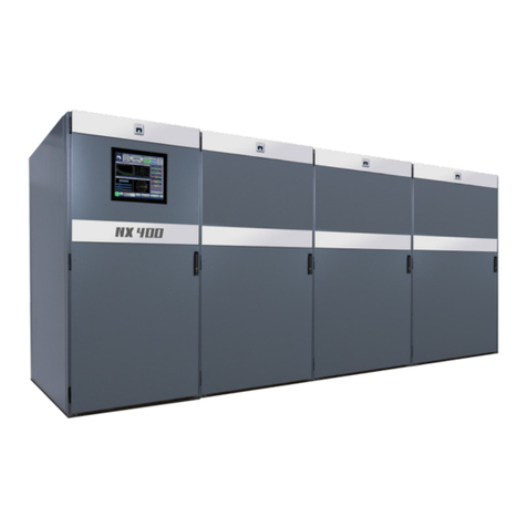
Nautel NX100 User manual

NX100 Transmitter
Installation Manual
Document:NHB-NX100-INS
Issue: 3.2 2017-03-31
Status: Standard


Nautel Limited
10089 Peggy’s Cove Road
Hackett’s Cove, NS Canada B3Z 3J4
Phone: +1.902.823.3900 or
Toll Free: +1.877.6NAUTEL (6628835) (Canada & USA only)
Fax: +1.902.823.3183
Nautel Inc.
201 Target Industrial Circle
Bangor, Maine USA 04401
Phone: +1.207.947.8200
Fax: +1.207.947.3693
Customer Service (24 hour support)
+1.877.628.8353 (Canada & USA only)
+1.902.823.5100 (International)
Email: [email protected]
Web: www.nautel.com
The comparisons and other information provided in this document
have been prepared in good faith based on publicly available
information. The reader is encouraged to consult the respective
manufacturer's most recent published data for verification.
© Copyright 2017 NAUTEL. All rights reserved.


NX100 Installation Manual Table of contents
Page v
Contents
Release control record vii
Preparing for installation 1-1
Unpacking and positioning 2-1
Connecting transformer taps/load wiring 3-1
Connecting the station reference ground 4-1
Connecting ac power 5-1
Adjusting the spark gap 6-1
Installing audio inputs 7-1
Planning complete? 7-1
Routing cables 7-1
Setting Exgine audio parameters 7-4
Installing control/monitor wiring 8-1
Planning complete? 8-1
Routing cables 8-1
Commissioning tasks 9-1
Pre-commissioning tasks 9-1
Commissioning 9-3
Going on-air 9-6

NX100 Installation Manual Table of contents
Page vi Issue 3.2 2017-03-31
Parts and tools 10-1
Contacting Nautel 10-1
Parts supplied by Nautel 10-1
Parts not supplied by Nautel 10-2
Parts ordering 10-2
Module replacement program 10-2
Tools for installation 10-3
Pre-installation / Installation assistance 11-1
Pre-installation consulting 11-1
Installation and commissioning service 11-1
Online documentation 11-3
On-site support 11-3
Training 11-3
Standard warranty 11-4
Extended warranties 11-8
List of terms 12-1

NX100 Installation Manual
Issue 3.2 2017-03-31 Page vii
Release control record
Issue Date Reason
3.0 2012-11-01 Release 3 of product (NARA52B)
3.1 2016-02-08 Section 9, sub-paragraphTurning on theTransmitter:
improved and added various steps.
Section 9, sub-paragraph Modulation Checks: added
NOTE after step 4 to maintain positive and negative
modulation peaks within specification.
3.2 2017-03-31 Section 2: improved and added various steps.
Section 3: added clarification about phase
connections and taps on transformer windings.
Section 6: updated Table 6.1.

NX100 Installation Manual
Page viii Issue 3.2 2017-03-31

NX100 Installation Manual Preparing for installation
Issue 3.2 2017-03-31 Page 1-1
Section 1: Preparing for installation
Before installing your NX100 transmitter, perform the following steps:
1. Ensure that you have performed the pre-installation tasks described in the
NX100 Pre-installation Manual.
2. Make sure that you received all the components. (Check your packing list.)
3. Inspect all crates and packages for damage.
4. Report any damage immediately to your Nautel sales representative and the carrier.
5. Move the crates as close as possible to the transmitter’s planned location.
6. Unpack the crates in accordance with the instructions provided on the outside of the crates.
• For each crate, remove the panel labelled open this side. The panel is attached using
Philips head screws.
• Remove any visible packing material, including braces, from the crate's interior.
7. Review any assembly notes or instructions contained inside the transmitter crates. (For sites
requiring custom configurations, the instructions provided with the transmitter replace the
instructions provided here.)
8. Gather the parts and tools you will need for installation. For a list of required tools, see
“Parts and tools” on page 10-1.
9. When you are ready to install the NX100 transmitter, follow the steps shown in Figure 1.1
on page 1-2.
TIP When you have completed a task or step, put a check mark beside the step
number.
CAUTION:
FAILURE TO COMPLY WITH RECOMMENDATIONS MAY VOID YOUR MANUFACTURER’S
WARRANTY. FOR MORE INFORMATION, REVIEW YOUR WARRANTY DOCUMENTS.

NX100 Installation Manual Preparing for installation
Page 1-2 Issue 3.2 2017-03-31
Figure 1.1: Flowchart - Installing the transmitter
Unpacking and positioning - see page 2-1
Connecting the station reference ground - see page 4-1
Connecting transformer taps/load wiring - see page 3-1
Installing control/monitor wiring - see page 8-1
Commissioning tasks - see page 9-1
Perform operational tasks:
“Commissioning”, “Modulation checks” and “Going on-air”, beginning on page 9-3
Connecting ac power - see page 5-1
Installing audio inputs - see page 7-1
Adjusting the spark gap - see page 6-1

NX100 Installation Manual Unpacking and positioning
Issue 3.2 2017-03-31 Page 2-1
Section 2: Unpacking and positioning
To install an NX100 transmitter, perform the following tasks:
1. Lift and slide the transmitter cabinets off the base of their crates. The NX100 contains two
main crates - a control cabinet and a transformer cabinet. Crated and uncrated cabinet
weights are shown in Table 2.1. An additional crate, which contains the ac safety interlock
switch, may be provided.
Table 2.1: NX100 Cabinet Weights
2. Using necessary mechanical assistance (forklift, etc), position the two cabinets in their final
location.See Figure 2.1 on page 2-2 for cabinet layout.
WARNING:
Do not move the transformer cabinet unless sufficient manpower or
mechanical assistance is available to move it into position without
damaging the cabinet or causing injury to personnel.
Note:
The position of the transformer cabinet can be determined by the user. The cabinet’s location
should accommodate input wiring from the ac power source (or ac power disconnect switch), output
wiring to each of the transmitter cabinets, as well as a cable carrying system to support the output
wiring.
Cabinet Crated Weight
kg (lbs) Uncrated Weight
kg (lbs)
687 (1515)
567 (1250)
845 (1863)
753 (1659)
Control Cabinet
Transformer Cabinet
Ac Power Disconnect Switch TBA (TBA) TBA (TBA)

NX100 Installation Manual Unpacking and positioning
Page 2-2 Issue 3.2 2017-03-31
Figure 2.1: NX100 Cabinet Layout
3. Verify that the ac power cable from the ac power disconnect switch reaches the entry point
in the power transformer cabinet.
4. Cover the top of the transmitter, using a plastic sheet or suitable equivalent, to prevent debris
and hardware from falling into the transmitter. Keep the sheet on the transmitter until
Section 9, “Commissioning tasks”.
5. The transmitter is factory configured for open loop cooling however, if you are using the
optional closed air cooling configuration (see the NX100 Pre-Installation Manual for details),
follow the installation steps below:
• Obtain the cover plate (Nautel Part # 207-8211) packed with the NX100 ancillaries.
• Remove the nine (9) M4 screws that secure the filter brackets to the rear door and
remove the air filter and brackets (see Figure 2.2 on page 2-5).
• Install the cover plate using the screws from the previous step in place of the removed
brackets.
• Remove the top cover plate (see Figure 2.2 on page 2-5) to uncover the intake grill
necessary for the ducted incoming air.
100 kW
Control
Cabinet
RACK 1
Transformer
Cabinet
T1
(position is
user-defined)
Cable Tray System (shown
with overhead supports)

NX100 Installation Manual Unpacking and positioning
Issue 3.2 2017-03-31 Page 2-3
6. Install the antenna ground switch on top of the transmitter cabinet as follows:
•Locate the antenna ground switch (Nautel Part # 207-8320-04) that was packed with the
ancillary crate for shipping.
• Open the front door of the transmitter and unlock and open the filter door to gain
access to the inside of the transmitter cabinet.
• Remove any protective wrapping from the antenna ground switch and position it on top
of the transmitter cabinet, noting proper orientation and that the aluminum rod
protruding from the bottom of the antenna ground switch must pass through a clearance
hole in the transmitter cabinet (see Figure 2.3 on page 2-6).
• See Figure 2.3 on page 2-6. Temporarily remove the right-hand side cover (as viewed
from the front) from the antenna ground switch, to allow access to the securing
hardware. Using the hardware provided with the transmitter, secure the antenna ground
switch to the top of the cabinet using 12 sets of M10 hardware (dome head bolt, split
washer, flat washer, nut and acorn nut). Secure the aluminum rod to the output plate
using an M10 button-head cap-screw, split washer and flat washer. Ensure hardware is
tight.
7. Install the RF output connector, which was partially disassembled for shipment, on top of
the antenna ground switch installed in Step 6. Re-install the antenna ground switch’s right-
hand side cover.
8. Close and lock the filter panel. Close the front door of the transmitter. Continue with
transmitter installation.
9. Verify that the RF feed cable reaches the RF output connector on top of the control cabinet.
10. Open the rear door. Locate the arc detector assembly (A71) on the right-hand interior wall,
near the low voltage power supplies (see Figure 2.4 on page 2-7). Remove the packing
material that has been used to protect it from vibration damage during shipping. Close the
rear door.
WARNING:
Take special care when handling the UV sensor while removing the
packing material so it does not receive impact shock. Do not allow skin
contact with the glass face. Wear clean gloves to ensure no oils from
your skin contact the surface of the glass.

NX100 Installation Manual Unpacking and positioning
Page 2-4 Issue 3.2 2017-03-31
12. Locate the cable tray parts kit that was provided to support the cables that will connect ac
power between the ac power disconnect switch and the primary for the power transformer,
and also between the secondary of the power transformer and the transmitter cabinets.
These parts may have been provided by Nautel (Cable Tray Parts List # 207-8385-**) or
purchased from an alternate vendor. Install the cable tray system according to your
transmitter system dimensions. If the cable tray kit was purchased from Nautel, refer to
Section 5 - Electrical Requirements of the NX100 Pre-installation Manual for standard
drawings and parts lists or to the provided system manual for custom drawings and parts lists
- to aid in the installation.
11. Obtain four stiffener brackets [Nautel Part # 207-8296 (qty 1), 207-8296-01 (qty 1) and
207-8296-02 (qty 2)] for each transmitter cabinet from the ancillary kit. Install them on the
top of each cabinet as shown in Figure 2.5 on page 2-8. Use the existing hardware that
secures the exhaust duct's grill to secure the stiffener brackets. These brackets provide
additional mechanical strength to the top of the cabinet(s).

NX100 Installation Manual Unpacking and positioning
Issue 3.2 2017-03-31 Page 2-5
Figure 2.2: Installing Rear Plate and Removing Top Cover Plate - Closed Air Cooling
Remove the 9 M4 screws that
secure the filter bracket.
Use same holes and hardware
to install cover plate.
Partial Rear View
Remove top cover plate.
Partial Top View

NX100 Installation Manual Unpacking and positioning
Page 2-6 Issue 3.2 2017-03-31
Figure 2.3: Installing Antenna Ground Switch
Aluminum Rod
(secure to probe bracket with
Four sets of M4 hardware
(packed with antenna
ground switch)
antenna ground switch)
M8 hardware, packed with
Antenna Ground Switch
(Nautel Part # 213-8320-04)

NX100 Installation Manual Unpacking and positioning
Issue 3.2 2017-03-31 Page 2-7
Figure 2.4: Location of Arc Detector Assembly
Partial Rear View; Rear Door
Removed for Clarity
Arc Detector Assembly (A71)

NX100 Installation Manual Unpacking and positioning
Page 2-8 Issue 3.2 2017-03-31
Figure 2.5: Installing Stiffener Brackets
Install stiffener brackets to
create a frame as shown.
Remove and re-use the
hardware securing the
exhaust duct grill to secure
the brackets.
Single-cabinet transmitter shown. For multi-cabinet
transmitters, repeat installation for each cabinet.

NX100 Installation Manual Connecting transformer taps/load wiring
Issue 3.2 2017-03-31 Page 3-1
Section 3: Connecting transformer taps/
load wiring
1. Before connecting ac wiring to the transformer, set the line voltage tap selections. Based on
your line to line voltage under full load, select the appropriate tap position identified on the
labels mounted on the terminal board end of the transformer. One label identifies the tap
number and the line-to-line voltage. Another label identifies the tap. All phase connections
must be set to the same tap (see Figure 3.1 on page 3-2 and Table 3.1). If necessary, use the
hardware already on each of the three phase connections to connect them to the new tap
positions, noting that the end of each phase connection consists of four copper straps (see
Figure 3.2 on page 3-2). Ensure the four copper straps for each phase are evenly split (i.e.,
two on top of loop, two on bottom), and secured to both sides of the tap. Be sure to scrape
any excess epoxy off the electrical joint area.
Table 3.1: Three-phase primary winding tap nominal voltages (rms, phase-to-phase)
2. Remove the back cover from the transformer cabinet.
Note:
It is important to choose the correct tap based on the loaded line-to-line voltage (i.e., the line voltage
present when the NX100 is operating at full power and full modulation) for maximum peak
modulation capability and maximum efficiency. If the loaded line-to-line voltage falls between two
tap settings, choose the higher voltage tap (this will maximize the NX100‘s power factor).
Voltage (V ac) Tap
340 6
360 5
380 4
400 3
420 2
440 1

NX100 Installation Manual Connecting transformer taps/load wiring
Page 3-2 Issue 3.2 2017-03-31
Figure 3.1: NX100 power transformer line voltage tap layout
Figure 3.2: Phase connection to transformer tap
2
3
4
5
6
X 3
H 3
X 2
H 2
X 1
H 1
1
X 0
PHASE CONNECTION
(FOUR COPPER STRAPS)
TAP
Other manuals for NX100
3
Table of contents
Other Nautel Transmitter manuals

Nautel
Nautel NX300 User manual

Nautel
Nautel NV30 User manual

Nautel
Nautel ND500II Manual

Nautel
Nautel XR3 User manual

Nautel
Nautel ND500II User manual

Nautel
Nautel NX Series Installation guide

Nautel
Nautel GV30N Programming manual

Nautel
Nautel NX100 Programming manual

Nautel
Nautel GV10 User manual

Nautel
Nautel NX50 User manual

Nautel
Nautel XR12 User manual

Nautel
Nautel NX15 Programming manual

Nautel
Nautel J1000 User manual

Nautel
Nautel VS300 User manual

Nautel
Nautel NX200 User manual

Nautel
Nautel VX150 Manual

Nautel
Nautel NV40 Programming manual

Nautel
Nautel V10 Operating instructions

Nautel
Nautel XR6 User manual

Nautel
Nautel VS1 User manual