Vega VEGABAR 86 User manual

Quick setup guide
Submersible pressure transmitter with
ceramic measuring cell
VEGABAR 86
Probus PA
Document ID: 46322

2
Contents
VEGABAR 86 • Probus PA
46322-EN-230914
Contents
1 For your safety ......................................................................................................................... 3
1.1 Authorised personnel ....................................................................................................... 3
1.2 Appropriate use................................................................................................................ 3
1.3 Warning about incorrect use............................................................................................. 3
1.4 General safety instructions............................................................................................... 3
1.5 Conformity........................................................................................................................ 3
1.6 NAMUR recommendations .............................................................................................. 4
1.7 Environmental instructions ............................................................................................... 4
2 Product description ................................................................................................................. 5
2.1 Conguration.................................................................................................................... 5
3 Mounting................................................................................................................................... 6
3.1 General instructions for use of the instrument .................................................................. 6
3.2 Ventilation and pressure compensation............................................................................ 6
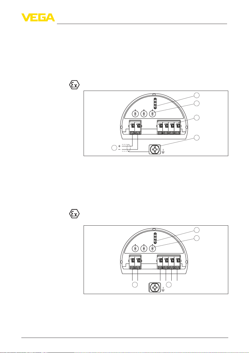
4 Connecting to the bus system................................................................................................ 8
4.1 Connecting....................................................................................................................... 8
4.2 Single chamber housing................................................................................................... 9
4.3 Double chamber housing ................................................................................................. 9
5 Set up with the display and adjustment module ................................................................ 11
5.1 Insert display and adjustment module............................................................................ 11
5.2 Parameter adjustment - Quick setup .............................................................................. 12
5.3 Parameter adjustment - Extended adjustment................................................................ 14
5.4 Menu overview ............................................................................................................... 15
6 Set up with smartphone/tablet, PC/notebook via Bluetooth ............................................. 18
6.1 Preparations................................................................................................................... 18
6.2 Connecting..................................................................................................................... 19
6.3 Sensor parameter adjustment ........................................................................................ 19
7 Supplement ............................................................................................................................ 21
7.1 Technical data ................................................................................................................ 21
Information:
This quick setup guide enables quick setup and commissioning of
your instrument.
You can nd supplementary information in the corresponding, more
detailed Operating Instructions Manual as well as the Safety Manual
that comes with instruments with SIL qualication. These manuals are
available on our homepage.
Operating instructions VEGABAR 86 - Probus PA: Document-
ID 45042
Editing status of the quick setup guide: 2023-09-06

3
1 For your safety
VEGABAR 86 • Probus PA
46322-EN-230914
1 For your safety
1.1 Authorised personnel
All operations described in this documentation must be carried out
only by trained and authorized personnel.
During work on and with the device, the required personal protective
equipment must always be worn.
1.2 Appropriate use
Model VEGABAR 86 is a pressure transmitter for level and gauge
measurement.
You can nd detailed information about the area of application in
chapter " Product description".
Operational reliability is ensured only if the instrument is properly
used according to the specications in the operating instructions
manual as well as possible supplementary instructions.
1.3 Warning about incorrect use
Inappropriate or incorrect use of this product can give rise to applica-
tion-specic hazards, e.g. vessel overll through incorrect mounting
or adjustment. Damage to property and persons or environmental
contamination can result. Also, the protective characteristics of the
instrument can be impaired.
1.4 General safety instructions
This is a state-of-the-art instrument complying with all prevailing
regulations and directives. The instrument must only be operated in
a technically awless and reliable condition. The operating company
is responsible for the trouble-free operation of the instrument. When
measuring aggressive or corrosive media that can cause a danger-
ous situation if the instrument malfunctions, the operating company
has to implement suitable measures to make sure the instrument is
functioning properly.
The safety instructions in this operating instructions manual, the
national installation standards as well as the valid safety regulations
and accident prevention rules must be observed.
For safety and warranty reasons, any invasive work on the device
beyond that described in the operating instructions manual may be
carried out only by personnel authorised by us. Arbitrary conversions
or modications are explicitly forbidden. For safety reasons, only the
accessory specied by us must be used.
To avoid any danger, the safety approval markings and safety tips on
the device must also be observed.
1.5 Conformity
The device complies with the legal requirements of the applicable
country-specic directives or technical regulations. We conrm con-
formity with the corresponding labelling.

4
1 For your safety
VEGABAR 86 • Probus PA
46322-EN-230914
The corresponding conformity declarations can be found on our
homepage.
1.6 NAMUR recommendations
NAMUR is the automation technology user association in the process
industry in Germany. The published NAMUR recommendations are
accepted as the standard in eld instrumentation.
The device fulls the requirements of the following NAMUR recom-
mendations:
• NE 21 – Electromagnetic compatibility of equipment
• NE 53 – Compatibility of eld devices and display/adjustment
components
• NE 107 – Self-monitoring and diagnosis of eld devices
For further information see www.namur.de.
1.7 Environmental instructions
Protection of the environment is one of our most important duties.
That is why we have introduced an environment management system
with the goal of continuously improving company environmental pro-
tection. The environment management system is certied according
to DIN EN ISO 14001.
Please help us full this obligation by observing the environmental
instructions in this manual:
• Chapter " Packaging, transport and storage"
• Chapter " Disposal"

5
2 Product description
VEGABAR 86 • Probus PA
46322-EN-230914
2 Product description
2.1 Conguration
The type label contains the most important data for identication and
use of the instrument:
• Instrument type
• Information about approvals
• Conguration information
• Technical data
• Serial number of the instrument
• QR code for device identication
• Numerical code for Bluetooth access (optional)
• Manufacturer information
To nd order data, documents or software related to your device, you
have the following options:
• Move to " www.vega.com" and enter in the search eld the serial
number of your instrument.
• Scan the QR code on the type label.
• Open the VEGA Tools app and enter the serial number under "
Documentation".
Type label
Documents and software

6
3 Mounting
VEGABAR 86 • Probus PA
46322-EN-230914
3 Mounting
3.1 General instructions for use of the instrument
Protect your instrument against moisture ingress through the following
measures:
• Use a suitable connection cable (see chapter " Connecting to
power supply")
• Tighten the cable gland or plug connector
• Lead the connection cable downward in front of the cable entry or
plug connector
This applies mainly to outdoor installations, in areas where high
humidity is expected (e.g. through cleaning processes) and on cooled
or heated vessels.
Note:
Make sure that during installation or maintenance no moisture or dirt
can get inside the instrument.
To maintain the housing protection, make sure that the housing lid is
closed during operation and locked, if necessary.
3.2 Ventilation and pressure compensation
1 2 3
6
6
6 6
6
5
4
Fig. 1: Position of the lter element
1 Plastic, stainless steel single chamber (precision casting)
2 Aluminium - single chamber
3 Stainless steel single chamber (electropolished)
4 Plastic double chamber
5 Aluminium, stainless steel double chamber housing (precision casting)
6 Filter element
With the following instruments a blind plug is installed instead of the
lter element:
Protection against mois-
ture
Filter element - Position

7
3 Mounting
VEGABAR 86 • Probus PA
46322-EN-230914
• Instruments in protection IP66/IP68 (1 bar) - ventilation via capillar-
ies in non-detachable cable
• Instruments with absolute pressure

8
4 Connecting to the bus system
VEGABAR 86 • Probus PA
46322-EN-230914
4 Connecting to the bus system
4.1 Connecting
The voltage supply and signal output are connected via the spring-
loaded terminals in the housing.
Connection to the display and adjustment module or to the interface
adapter is carried out via contact pins in the housing.
Information:
The terminal block is pluggable and can be removed from the
electronics. To do this, lift the terminal block with a small screwdriver
and pull it out. When reinserting the terminal block, you should hear it
snap in.
Proceed as follows:
1. Unscrew the housing lid
2. If a display and adjustment module is installed, remove it by turn-
ing it slightly to the left
3. Loosen compression nut of the cable gland and remove blind
plug
4. Remove approx. 10 cm (4 in) of the cable mantle, strip approx.
1 cm (0.4 in) of insulation from the ends of the individual wires
5. Insert the cable into the sensor through the cable entry
1 2
Fig. 2: Connection steps 5 and 6
1 Single chamber housing
2 Double chamber housing
6. Insert the wire ends into the terminals according to the wiring plan
Note:
Solid cores as well as exible cores with wire end sleeves are insert-
ed directly into the terminal openings. In case of exible cores without
end sleeves, press the terminal from above with a small screwdriver,
the terminal opening is then free. When the screwdriver is released,
the terminal closes again.
7. Check the hold of the wires in the terminals by lightly pulling on
them
8. Connect the shielding to the internal ground terminal, connect the
external ground terminal to potential equalisation
Connection technology
Connection procedure

9
4 Connecting to the bus system
VEGABAR 86 • Probus PA
46322-EN-230914
9. Tighten the compression nut of the cable entry gland. The seal
ring must completely encircle the cable
10. Reinsert the display and adjustment module, if one was installed
11. Screw the housing lid back on
The electrical connection is nished.
4.2 Single chamber housing
The following illustration applies to the non-Ex, Ex ia and Ex d version.
5
00
5
1
6
2
7
3
8
4
9
0
5
1
6
2
7
3
8
4
9
1
0
1
678
Bus
2
3
4
5
12
+
( ) (-)
1
Fig. 3: Electronics and connection compartment - single chamber housing
1 Voltage supply, signal output
2 For display and adjustment module or interface adapter
3 Selection switch for instrument address
4 For external display and adjustment unit
5 Ground terminal for connection of the cable screening
4.3 Double chamber housing
The following illustrations apply to the non-Ex as well as to the Ex-ia
version.
11
5
00
5
1
6
2
7
3
8
4
9
0
5
1
6
2
7
3
8
4
9
1
0
1
678
Bus
2
3
12
+
( ) (-)
Fig. 4: Electronics compartment - double chamber housing
1 Internal connection to the connection compartment
2 Contact pins for the display and adjustment module or interface adapter
3 Selection switch for bus address
Electronics and connec-
tion compartment
Electronics compartment

10
4 Connecting to the bus system
VEGABAR 86 • Probus PA
46322-EN-230914
Bus
5
12
+
( ) (-)
678
2
3
4
1
Fig. 5: Connection compartment - double chamber housing
1 Voltage supply, signal output
2 For display and adjustment module or interface adapter
3 For external display and adjustment unit
4 Ground terminal for connection of the cable screening
Connection compartment

11
5 Set up with the display and adjustment module
VEGABAR 86 • Probus PA
46322-EN-230914
5 Set up with the display and adjustment
module
5.1 Insert display and adjustment module
The display and adjustment module can be inserted into the sensor
and removed again at any time. You can choose any one of four dier-
ent positions - each displaced by 90°. It is not necessary to interrupt
the power supply.
Proceed as follows:
1. Unscrew the housing lid
2. Place the display and adjustment module on the electronics in the
desired position and turn it to the right until it snaps in.
3. Screw housing lid with inspection window tightly back on
Disassembly is carried out in reverse order.
The display and adjustment module is powered by the sensor, an ad-
ditional connection is not necessary.
Fig. 6: Installing the display and adjustment module in the electronics compart-
ment of the single chamber housing

12
5 Set up with the display and adjustment module
VEGABAR 86 • Probus PA
46322-EN-230914
1 2
Fig. 7: Installing the display and adjustment module in the double chamber
housing
1 In the electronics compartment
2 In the connection compartment
Note:
If you intend to retrot the instrument with a display and adjustment
module for continuous measured value indication, a higher lid with an
inspection glass is required.
5.2 Parameter adjustment - Quick setup
To quickly and easily adapt the sensor to the application, select the
menu item " Quick setup" in the start graphic on the display and
adjustment module.
Carry out the following steps in the below sequence.
You can nd " Extended adjustment" in the next sub-chapter.
Sensor address
In the rst menu item you have to enter a sensor address. The selec-
tion switches on the electronics module are preset to sensor address
126. This means that the sensor address can be changed via the
display and adjustment module.
Measurement loop name
In this menu item you assign a suitable measurement loop name.
Permitted are names with a maximum of 19 characters.
Quick setup - Presettings

13
5 Set up with the display and adjustment module
VEGABAR 86 • Probus PA
46322-EN-230914
Application
In this menu item, you activate/deactivate the Secondary sensor for
the electronic dierential pressure and select the application. The ap-
plication comprises process pressure and level measurement.
Units
In this menu item you determine the adjustment and temperature
units of the instrument. Depending on the selected application in the
menu item " Application", dierent adjustment units are available.
Position correction
In this menu item you compensate the inuence of the installation
position of the instrument (oset) on the measured value.
Zero adjustment
In this menu item you carry out the zero adjustment for the process
pressure.
Enter the corresponding pressure value for 0 %.
Span adjustment
In this menu item you carry out the span adjustment for the process
pressure
Enter the corresponding pressure value for 100 %.
Position correction
In this menu item you compensate the inuence of the installation
position of the instrument (oset) on the measured value.
Max. adjustment
In this menu item you carry out the max. adjustment for level
Enter the percentage value and the corresponding value for the max.
level.
Min. adjustment
In this menu item you carry out the min. adjustment for level
Enter the percentage value and the corresponding value for the min.
level.
The quick setup is nished.
Quick setup - Process
pressure measurement
Quick setup - Level meas-
urement

14
5 Set up with the display and adjustment module
VEGABAR 86 • Probus PA
46322-EN-230914
VEGABAR 86 always measures pressure independently of the pro-
cess variable selected in the menu item " Application".To output the
selected process variable correctly, an allocation of the output signal
to 0 % and 100 % must be carried out (adjustment).
During adjustment, the pressure is entered e.g. for the level with full
and empty vessel, see following example:
2
1
100%
0%
2 m
(78.74
")
Fig. 8: Parameter adjustment example Min./max. adjustment, level measure-
ment
1 Min. level = 0 % corresponds to 0.0 mbar
2 Max. level = 100 % corresponds to 196.2 mbar
If these values are not known, an adjustment with lling levels of e.g.
10 % and 90 % is also possible. By means of these settings, the real
lling height is then calculated.
The actual product level during this adjustment is not important,
because the min./max. adjustment is always carried out without
changing the product level. These settings can be made ahead of
time without the instrument having to be installed.
5.3 Parameter adjustment - Extended adjustment
For technically demanding measuring points, you can carry out
extended settings in " Extended adjustment".
The main menu is divided into ve sections with the following func-
tions:
Parameterization example
Main menu

15
5 Set up with the display and adjustment module
VEGABAR 86 • Probus PA
46322-EN-230914
Setup: Settings, for example, to measurement loop name, applica-
tion, units, position correction, adjustment, AI FB 1 Channel - scaling
- damping
Display: Settings, e.g., for language, measured value display, lighting
Diagnosis: Information, e.g. on instrument status, peak indicator,
measurement reliability, AI FB 1 simulation
Additional adjustments: PIN, date/time, reset, copy function
Info: Instrument name, hardware and software version, date of manu-
facture, sensor features
To ensure optimum adjustment of the measurement, the individual
submenu items in the main menu " Setup" should be selected one
after the other and provided with the correct parameters. The menu
items are described in the following.
5.4 Menu overview
The following tables show the adjustment menu of the instrument.
Depending on the instrument version or application, all menu items
may not be available or some may be dierently assigned.
Setup
Menu item Parameter Default value
Sensor address 126
Measurement loop name 19 alphanumeric characters/special
characters
Sensor
Application Level, process pressure Level
Secondary Device for electronic dieren-
tial pressure 1)
Deactivated
Units Adjustment unit (m, bar, Pa, psi … user-
dened)
mbar (with nominal measuring range
≤ 400 mbar)
bar (with nominal measuring ranges
≥ 1 bar)
Temperature unit (°C, °F) °C
Position correction 0.00 bar
Adjustment Zero/Min. adjustment 0.00 bar
0.00 %
Span/Max. adjustment Nominal measuring range in bar
100.00 %
Linearisation Linear, cylindrical tank, … user-dened Linear
1) Parameter only active if the instrument is connected to the Secondary sensor

16
5 Set up with the display and adjustment module
VEGABAR 86 • Probus PA
46322-EN-230914
Menu item Parameter Default value
AI FB 1 Channel Primary Value
Scaling format Pressure
Scaling 0 % corresponds to 0 bar
100 % corresponds to measuring range
nal value
Damping PV FTime 1 s
Lock adjustment Blocked, released Released
Display
Menu item Default value
Menu language Selected language
Displayed value 1 Signal output in %
Displayed value 2 Ceramic measuring cell: Measuring cell temperature in °C
Metallic measuring cell: Electronics temperature in °C
Display format Number of positions after the decimal point, automatically
Backlight Switched on
Diagnostics
Menu item Parameter Default value
Device status -
Peak indicator Pressure Current pressure measured value
Peak indicator temp. Temperature Actual measuring cell and electronic tem-
perature
Simulation Pressure, percent, signal output,
linearized percent, measuring cell tem-
perature, electronics temperature
Process pressure
Additional adjustments
Menu item Parameter Default value
Date/Time Actual date/Actual time
Reset Delivery status, basic settings
Copy instrument settings Read from sensor, write into sensor
Scaling Scaling size Volume in l
Scaling format 0 % corresponds to 0 l
100 % corresponds to 100 l
Special parameters Service-Login No reset

17
5 Set up with the display and adjustment module
VEGABAR 86 • Probus PA
46322-EN-230914
Info
Menu item Parameter
Device name VEGABAR 86
Instrument version Hardware and software version
Factory calibration date Date
Probus Ident Number Identication number of the instrument on a Probus system
Sensor characteristics Order-specic characteristics

18
6 Set up with smartphone/tablet, PC/notebook via Bluetooth
VEGABAR 86 • Probus PA
46322-EN-230914
6 Set up with smartphone/tablet, PC/
notebook via Bluetooth
6.1 Preparations
Make sure that the Bluetooth function of the display and adjustment
module is activated. For this, the switch on the bottom side must be
set to " On".
1
On
O
Fig. 9: Activate Bluetooth
1 Switch
On = Bluetooth active
O = Bluetooth not active
The security concept of Bluetooth operation absolutely requires that
the default setting of the sensor PIN be changed. This prevents unau-
thorized access to the sensor.
The default setting of the sensor PIN is " 0000". First of all you have
to change the sensor PIN in the adjustment menu of the sensor, e.g.
to " 1111":
1. Go to setup via the extended operation
2. Lock operation by changing sensor PIN
3. Enable operation by entering the sensor PIN once more
Activate Bluetooth
Change sensor PIN

19
6 Set up with smartphone/tablet, PC/notebook via Bluetooth
VEGABAR 86 • Probus PA
46322-EN-230914
Sensor adjustment via the display/adjustment module or PACTware/
DTM by means of VEGACONNECT is thus released again. For ac-
cess (authentication) with Bluetooth, the changed PIN is still eective.
Note:
Bluetooth access can only be established if the current sensor PIN
diers from the default setting " 0000". It is possible both when the
adjustment is unlocked and when it is locked.
6.2 Connecting
Smartphone/Tablet
Start the adjustment app and select the function "Setup". The smart-
phone/tablet searches automatically for Bluetooth-capable instru-
ments in the area.
PC/Notebook
Start PACTware and the VEGA project assistant. Select the device
search via Bluetooth and start the search function. The device auto-
matically searches for Bluetooth-capable devices in the vicinity.
The message " Instrument search running" is displayed. All devices
found are listed in the operating window. The search is automatically
continued continuously.
Select in the device list the requested device.The message " Con-
necting" is displayed.
For the rst connection, the operating device and the sensor must
authenticate each other. After successful authentication, the next con-
nection functions without authentication.
For authentication, enter in the next menu window the 4-digit sensor
PIN.
6.3 Sensor parameter adjustment
The sensor parameterization is carried out via the adjustment app on
the smartphone/tablet or the DTM on the PC/notebook.
Preparations
Connecting
Authenticate

20
6 Set up with smartphone/tablet, PC/notebook via Bluetooth
VEGABAR 86 • Probus PA
46322-EN-230914
Fig. 10: Example of an app view - Setup sensor adjustment
App view
Other manuals for VEGABAR 86
14
Table of contents
Other Vega Transmitter manuals

Vega
Vega VEGABAR 66 User manual

Vega
Vega VEGABAR 82 User manual

Vega
Vega VEGABAR 86 User manual

Vega
Vega VEGADIF 65 User manual

Vega
Vega VEGABAR 87 User manual

Vega
Vega VEGABAR 82 User manual

Vega
Vega VEGABAR 83 User manual

Vega
Vega VEGADIF 65 User manual

Vega
Vega VEGABAR 83 User manual

Vega
Vega VEGABAR 14 User manual

Vega
Vega VEGABAR 83 User manual

Vega
Vega VEGAPULS 62 User manual

Vega
Vega VEGABAR 54 User manual

Vega
Vega VEGABAR 82 User manual

Vega
Vega VEGABAR 29 User manual

Vega
Vega VEGABAR 86 User manual

Vega
Vega VEGABAR 82 User manual

Vega
Vega VEGABAR 86 User manual

Vega
Vega VEGABAR 81 User manual

Vega
Vega VEGABAR 82 User manual