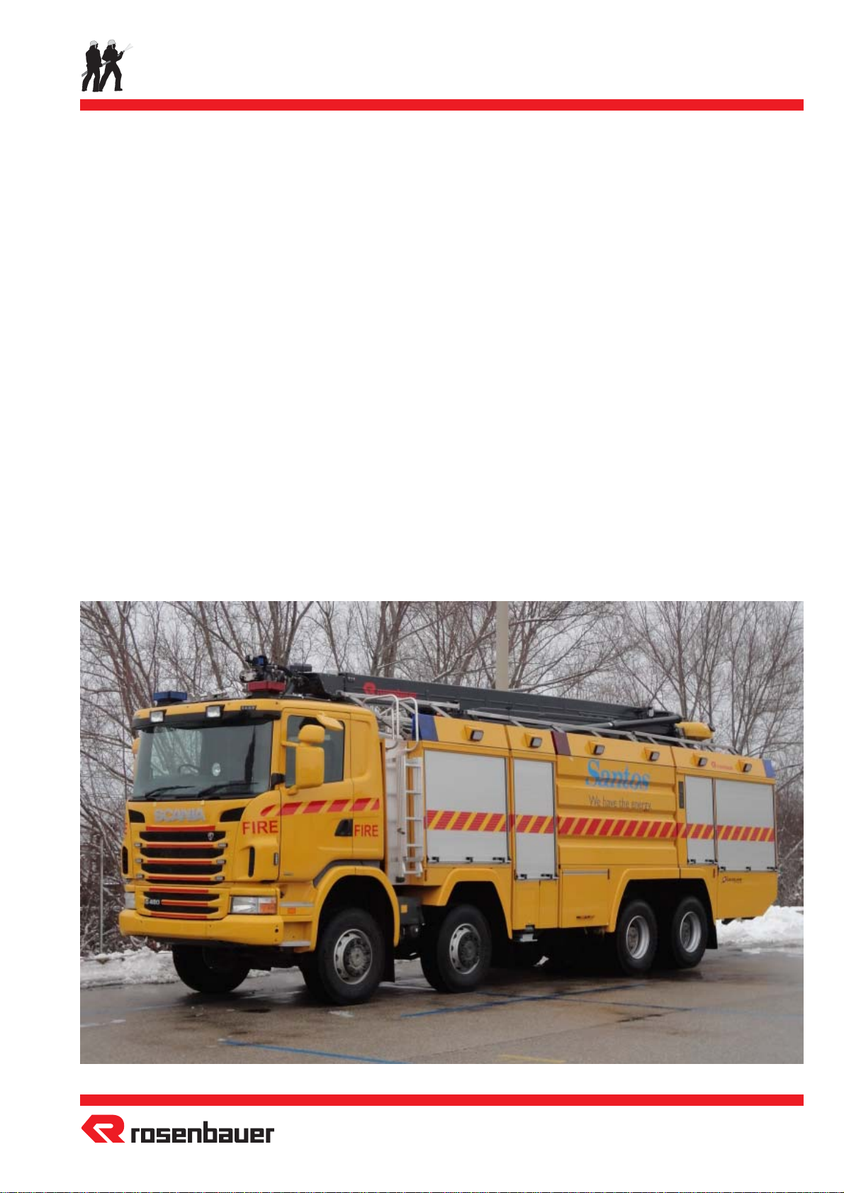
Rosenbauer SLF 2250 User manual

SLF 2250/4000
Hydromatic Stinger
Page - 1 -
© 2014
OPERATION MANUAL
25.11.2014 / Rev. 00 / CSD-CSpa
FIRE FIGHTING TRUCK
FIRE FIGHTING TRUCK
SLF 2250/4000
SLF 2250/4000
Hydromatic Stinger
Hydromatic Stinger

Page - 2 -
© 2014
SLF 2250/4000
Hydromatic Stinger Table of Contents
Table of Contents
Table of Contents...................................................................... 2
Introduction .............................................................................. 3
Manufacturer and After-Sales-Service Address ....................... 3
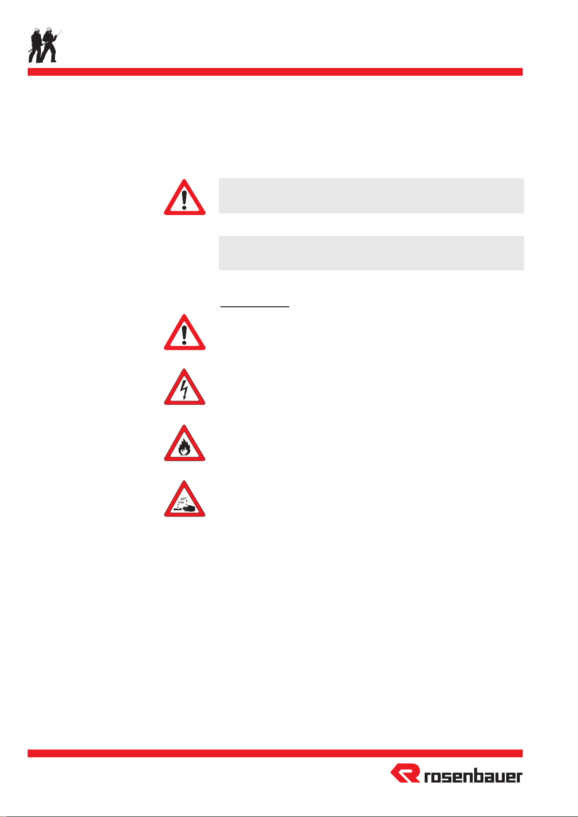
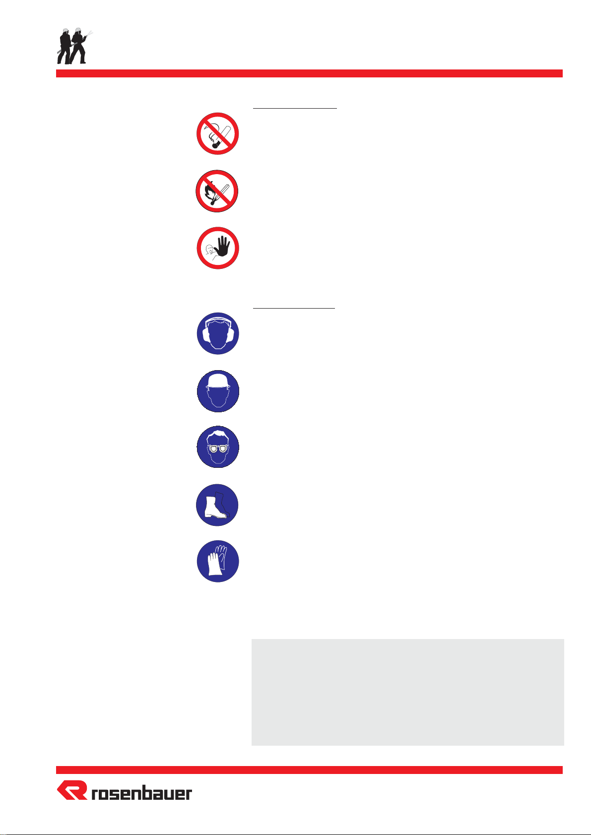
List of Conventional Signs........................................................ 4
Technical Data ......................................................................... 6
Technical Description ............................................................ 18
Preparation for Use................................................................ 49
Engaging the Water Pump...................................................... 50
Engaging the Hydraulic Oil Pumps ....................................... 52
Tank Suction Operation.......................................................... 53
Drafting Operation from Open Water Source........................ 54
Hydrant / Supply Operation ................................................... 56
Pump Pressure Governor ....................................................... 58
Foam Operation ..................................................................... 59
Watch out during Pump Operation ........................................ 62
Disengaging the Pump System ............................................... 63
Stinger and Stinger Turret Operation .................................... 64
Roof Turret RM 60 C .............................................................. 71
Rapid Intervention System ...................................................... 76
Filling the Water Tank via the Pump...................................... 77
Filling the Water Tank via Tank Supply Lines ....................... 78
Filling the Foam Compound Tank ......................................... 79
Compressed Air Supply .......................................................... 81
Emergency control of Electro Pneumatic Solenoids .............. 81
Emergency Control of Pneumatic Actuators .......................... 83
Flushing after Foam Operation.............................................. 84
Drainage of the Pump System /
Operation in Cold Climates.................................................... 89
Checking Procedures.............................................................. 92
Maintenance Procedures........................................................ 95
Service Procedures ................................................................. 97
Problems and their Solutions ............................................... 106
Safety Instructions for Hydraulic Installations .................... 107
Handling and Storing Electronic Components..................... 109
Tilting of Cabin..................................................................... 111
Repetitive Test Cycle for Electrical Components ................. 112
Hints for Disposal................................................................. 113
Annex
Safety Precautions
Piping Diagram
Stinger operation manual

SLF 2250/4000
Hydromatic Stinger
Page - 3 -
© 2014
Introduction
Introduction
This operation manual is designed to provide clear answers to
essential questions concerning the operation and maintenance of
this product.
To ensure continuous operational reliability, we strongly recom-
mend that all service, inspection and maintenance work listed in
this manual be carried out on time.
Forthispurpose,Rosenbauerservicestationsareatyourdisposal.
ATTENTION !
Please read this manual carefully before starting operation.
Obey all instructions and hints.
Only personnel familiar with this manual, the vehicle, inclusive
equipment, according operation, local safety regulations and
accident prevention may operate this unit.
Rosenbauer is not liable for any injury or damage caused by
personnelunfamiliarwiththeoperationalproceduresdescribedin
this manual, failing to comply with the operation manual and/or
failing to comply with regulations, subsequent procedures, safety
and accident prevention.
ROSENBAUER and its affiliates thank you for your
confidence in our products and is sure that delivered
products will provide quick, reliable, quality service in
the years to come.
Several models whose principal components are identi-
cal are dealt with in this operation manual. Besides, this
includesoptionalfeatures. Your unitmaytherefore differ
from some of the descriptions and illustrations.
For more information kindly contact the Rosenbauer After Sales
Service Department or your nearest Rosenbauer representative.
Manufacturer and After-Sales-Service Address
Rosenbauer International Aktiengesellschaft
P.O.Box 176
A-4021 Linz
AUSTRIA
Telephone No.: 0043 / 732 - 6794 - 0
Telefax No.: 0043 / 732 - 6794 - 312
e-mail: [email protected]
Internet: www.rosenbauer.com
Works Order Number
Identifying the works order number is important.
Itisstampedatthetypeplateonthe"Superstructure" platelocated
near the co-driver entrance.
Works order number of your vehicle
FAHRZEUGTYPE
VEHICLE TYPE
BAUJAHR
YEAR OF CONSTR.
FAHRGESTELL
CHASSIS
AUFBAU
SUPERSTRUCTURE
Feuerwehrtechnik
Fire Fighting Technology
Rosenbauer International
Aktiengesellschaft
Hersteller
Manufacturer
Nr./No.
Hersteller
Manufacturer
Nr./No.
MOTOR
ENGINE
Hersteller
Manufacturer
Nr./No.
A-4060 Leonding, Paschinger Str.90
Austria 085165-001
X 2 S 0 3 4 1

Page - 4 -
© 2014
SLF 2250/4000
Hydromatic Stinger Signs and Symbols
Warning Signs
-This warning sign indicates possible danger to the life and
health of persons involved.
-This warning sign indicates electrical hazards.
-This warning sign indicates fire hazards.
-This warning sign indicates danger of cauterization.
List of Conventional Signs
This sign indicates optional equipment that means:
The described position may not be installed on your unit, but it is
a customer specific installation.
CAUTION !
This warning indicates possible danger to life and health of persons.
ATTENTION !
This warning indicates other dangers.
*
Note: For all valve descriptions DN stands for Internal DiameterDN

SLF 2250/4000
Hydromatic Stinger
Page - 5 -
© 2014
Signs and Symbols
Prohibition Signs
- No smoking
-Handling of open flames is prohibited.
-Keep your distance! Be extremely careful!
Mandatory Signs
-Use ear protection.
-Wear helmet.
-Wear protective eye glasses.
-Wear protective work boots.
-Wear protective work gloves.
ATTENTION !
All superstructural components (e.g. hinged steps, doors, ladder,
etc.), are to be used for their intended purpose only.
For example:
Jumping out of the crew cabin onto the last step, transportation of
heavyequipmentonahingedsteporfixingropesto theladder,are
all contrary to their intended purpose.

Page - 6 -
© 2014
SLF 2250/4000
Hydromatic Stinger
Technical Data
Chassis
Manufacturer and type: Scania G480 LB RHD
Engine: Scania DC 13 07 Euro 5
Performance: 352 kW at 1800 rpm
Voltage of consumers: 24 Volt
Batteries: 2 x 12 Volt / 180 Ah
Generator: 28 Volt / 150 Ampere
Transmission: Allison HD4500
Power Take Off (P.T.O.) I: Chelsea870Cforthehydr.oilpumps
Ratio: nengine x 1.33
Rotating direction: counterclockwise
Performance: 175 kW at 1800 rpm(engine speed)
Torque: 698 Nm
Power Take Off (P.T.O.) II: N 100 for water pump
Ratio: nengine x 1.28
Rotating direction: counterclockwise
Torque: 1700 Nm
Wheel base: 5700 + 1350 mm
Tyres: 315/80 R 22.5
Powered axle: 8 x 4
Cabin: 1 + 1 men
Dimensions: Length......................... 11600 mm
Width ............................ 2510 mm
Height ........................... 3800 mm
Permissible weight: Front axle I .........................7100 kg
Front axle II........................7100 kg
Rear axle I ........................10500 kg
Rear axle II .......................10500 kg
Gross vehicle weight ..........35200 kg
Ramp angles: Angle of approach ..................... 18
°
Ramp angle .............................. 15
°
Angle of departure ..................... 11
°
Technical Data
ATTENTION !
Always use similar tyres when chang-
ing or replacing a tyre to allow maxi-
mum driving performance!
Itisstrictlyprohibitedtouseretreaded
tyres.
When changing the tyre type call for
written approval from Rosenbauer.
ATTENTION !
The vehicle should be operated by
trained and certified personnel.
When driving on inclines, uneven or
slippery roads / surfaces, as well as
duringcuresorexpectingalanechange,
a prudent and precautionary driving
style should be used.
The instructions in the chassis opera-
torsmanualshouldbestrictlyfollowed,
in particular when driving in off-road
conditions.
For further technical data please refer
to the chassis manufacturers manual.

SLF 2250/4000
Hydromatic Stinger
Page - 7 -
© 2014
Technical Data
Water tank
Manufacturer: ROSENBAUER
Capacity: 2250 l
Maximum tank pressure: 0.2 bar
Material: GFK
glass fibre reinforced plastic
Manhole: removable ø 600 mm cover
Overflow: 2 x with over- and under pressure
diaphragm
Tank level indicator: fludometer
Hydrant fill connection: DN 65butterfly valve with SART 65
female coupling and a non return
valve on the tank flange. These
connectionsareontheleftandright
hand sides.
Pump fill connection: DN 50 ball valve
Suction connection: DN 200 butterfly valve
Tank roof: GFK with anti-slip coating
Drainage: DN 50 ball valve

Page - 8 -
© 2014
SLF 2250/4000
Hydromatic Stinger Technical Data
Foam compound tank
Manufacturer: ROSENBAUER
Capacity: 4000 l
Maximum tank pressure: 0.2 bar
Material: GFK
glass fibre reinforced plastic
Location: integrated into the front part of the
tank
Manhole: removable ø 600 mm cover
Overflow: with lamellar case
Tank level indicator: fludometer
and visual gauge on the left and
right hand sides
Suction connection: DN 80 butterfly valve
Pump fill connection: DN 40 ball valve
Drain connection: DN 40 ball valve with SART 65
female coupling on the left hand
sides

SLF 2250/4000
Hydromatic Stinger
Page - 9 -
© 2014
Technical Data
Pump
Manufacturer and type: ROSENBAUER N 100
with pump pressure governor
Material casing: bronze
Material impeller: bronze
Design: single stage
Rotating direction: counterclockwise
Pump shaft seal: axial face seal on the pressure side
doublesealringsonthesuctionside
Performance
at tank suction operation: 10000 l/min at 10 bar
at 2.7 m suction height: 7000 l/min at 10 bar
Closing pressure: 0 l/min at 13.5 bar
Maximum pump speed: 1750 rpm
Operating ability: from -15˚ C to +50˚ C ambient
temperature
Allowed fluids: firefightingwaterordrinkingwater
Fluid temperature
range: from +4
°
to +60
°
C
Tank suction connection: DN 200 butterfly valve
Drafting connection: DN 125 butterfly valves with Storz
125 coupling left and right hand
sides
Hydrant/supply connection: 4 x DN 50 ball valves with SART 65
female couplings on the left and
right hand sides

Page - 10 -
© 2014
SLF 2250/4000
Hydromatic Stinger Technical Data
Pump
Pressure outlets: DN 125 butterfly valves with Storz
125 couplings on the left and right
hand sides
3xDN65butterflyvalveswithSART
65 male couplings on the left and
right hand sides
Hose reel: DN 40 ball valve
Roof turret: DN 100 butterfly valve
Stinger turret: DN 100 butterfly valve
Water tank pump fill line: DN 50 ball valve
Internal flushing valve: DN 40 ball valve
Priming line: DN 40 ball valve
Pump drainage: DN 25 ball valve
Drive: propellershaftfromvehiclesP.T.O.II

SLF 2250/4000
Hydromatic Stinger
Page - 11 -
© 2014
Technical Data
Pump gearbox for N 100
Manufacturer and type: ROSENBAUER gearbox N 100
Ratio
with reversal of rotation: Z1=64 : Z2=79 -> i=0,81
from counterclockwise to clockwise
without reversal
of rotation: Z1=53:Z2=64:Z3=79->itot=0.67
*
Casing material: light alloy
Priming pump
Manufacturer and type: ROSENBAUER KAP 600
Double Piston Priming Pump
Material: light alloy
Method of operation: displacement
Type of drive: double V-belt via the N 100 pump
shaft
Control: electrically with automatic control
Lubrication: oil bath lubrication
Performance of the
priming pump: 100 l to 75% vacuum within 10 sec

Page - 12 -
© 2014
SLF 2250/4000
Hydromatic Stinger Technical Data
Foam compound pump
Manufacturer and type: BEINLICH ZPD 4-517-MEN-L
Performance at
tank suction operation: 700 l/min at 16 bar
Foam compound viscosity: up to 300 cSt
Maximum pump speed: 1500 rpm
Material:
Pump casing: bronze
Pump shaft and gears: high-grade steel
Rotating direction of pump: counterclockwise
Design: gear pump
Tank suction line: DN 100 butterfly valve
Foam compound drafting
connection: DN 65 ball valve with SART 65
femalecouplingontheleftandright
handsidesinthe pumpcompartment
Pressure outlets:
Supply for all
foam proportioners: DN 65 ball valve
Supply for the
foam proportioner of
the RM 60 C: DN 40 ball valve
the Singer turret: DN 40 ball valve
Foam compound
discharge: DN65ballvalvewithSART65male
coupling on the left and right hand
sides
Foam compound tank
pump fill line: DN 50 ball valve
Drainage: DN 25 ball valve
Priming: DN 25 ball vlave
Drive: hydraulic motor
Sauer Danfoss
M50AW1N1M200VB
Displacement: 50 cm3/U
powerd by hydraulic pump
Sauer Danfoss
90R100KA5CD80L3C7E03GBA292924
Capacity: max. 100 cm3/U
powerd via P.T.O. II

SLF 2250/4000
Hydromatic Stinger
Page - 13 -
© 2014
Technical Data
Foam proportioning system
used for the turrets
and Storz 125 outlets:
Type: ACR 6"
Number: 4
Material: bronze
Proportioning rate: 0% to 7%
used for the left, right,
rear and front outlets:
Type: ACR 21/2"
Number: 6
Material: bronze
Proportioning rate: 0% to 7%
used for the Rapid Intervention System
on the right* and left hand sides:
Type: ACR 1.5"
Number: 1
Material: bronze
Proportioning rate: 0% to 7%

Page - 14 -
© 2014
SLF 2250/4000
Hydromatic Stinger Technical Data
Stinger
Manufacturer and type: ROSENBAUER Stinger
Maximum height: approx. 20 m (ground to turret
nozzle)
Mechanical radius: 21m(centreofturretbasetonozzle)
Maximum turret range: 13,5m(centreofvehicletothenozzle)
Rotation range: 360
°
Turret type: Rosenbauer RM 65 C Chem Chor
Nozzle: HSD 6000 CCN
Performance with boom
in transport position or
with Stinger supported by
the outriggers
full output: approx. 4800 l/min at 13.5 bar
reduced output: approx. 2200 l/min at 13.5 bar
Throwing range: approx. 90 m with water full output
approx. 70 m with reduced output
Control: electrohydraulically via radio
remote control
Nozzle slewing range:
Elevation: 180
°
Rotation: 180
°
Drive: hydraulic oil pump
connected to the P.T.O.
For further details please refer to the separate operation manual
of Stinger.

SLF 2250/4000
Hydromatic Stinger
Page - 15 -
© 2014
Technical Data
Roof turret
Type: ROSENBAUER RM 60 C
Location: mounted on the roof of
superstructure
Material: light alloy
Nozzle: HSD 7000
Performance with
full output: 7000 l/min at 10 bar
reduced output: 3000 l/min at 10 bar
Trowing range: approx. 80 m with full output
approx. 55 m with reduced output
Control: remotely controlled from driver´s
cabin via control handle
or manually from the vehicle´s roof
Slewing range:
Elevation: -15
°
to +70
°
Rotation: 270
°

Page - 16 -
© 2014
SLF 2250/4000
Hydromatic Stinger Technical Data
Rapid Intervention System
Manufacturer and type: ROSENBAUER
high pressure hose reel 06
Material: ABS/PE plastic
Brake: friction brake
Rewinding device: manually by crank
and electrically
Locations: in the rear left and right* locker
compartments
Nozzle: ROSENBAUER RB 101
Performance: 115 - 230 - 360 - 475 l/min at 7 bar
Equipment: with a 60 m DN 25 non-collapsible
rubber hose

SLF 2250/4000
Hydromatic Stinger
Page - 17 -
© 2014
Technical Data
Surrounding illumination
Search lights: 14 x 24 VDC / 10 Watt
Location: 6 projectors on the left and right
hand sides
2projectorsintherearofthevehicle
External supply
Power supply: 230 VAC / 50 or 60 Hz for the
battery charging unit
Battery charging unit: FRONIUS Acctiva Twin
Compressed air supply:
Location: via the combined power supply
connection at the driver´s cabin
entrance
Vehicle supply air compressor installation
Manufacturer and type: AGRE MK 282
For further technical data please refer to the separate operation
manual.

Page - 18 -
© 2014
SLF 2250/4000
Hydromatic Stinger Technical Description
Technical Description
Water pump
The pump consists mainly of the pump pressure casing, impellers,
pump shaft, diffusers, and pump shaft sealing.
The water penetrates the impeller via the suction inlet. This
process is called axial feed, since the water flows in the direction
of the central axis.
The water which enters through the suction inlet is then seized by
theimpeller(impellerblades);therebythewaterisdeflectedby90
°
andflung out ofthe impeller inthe direction verticallyto the shaft.
This is called radial discharge.
The water delivery depends mainly on the effect of centrifugal
force, therefore this type of pump is called a centrifugal pump.
Between the impeller and the diffuser, there is a small gap and the
diffuser, fixed on the pump casing, is stationary. The gap is
necessary in order to prevent the impeller and diffuser from
touching.
The energy of a streaming liquid is composed of velocity and
pressureforces andthe energyof velocitycan betransformed into
pressure. The water is discharged from the impeller at high
velocity and this transformation of velocity into pressure takes
place in the diffuser.
The cross sectional area through which the water passes from
entering the diffuser until leaving it, is enlarged gradually. The
velocitydecreaseswhilethestreamingquantityremainsunchanged.
Thepipecrosssectionsaredimensionedastobelargeenoughthat
the proportion of the velocity of the total energy at the pressure
outlet of the pump is so small that it can be ignored in comparison
to the proportion of pressure. Therefore only the suction lift of the
pump (which is the sum of the indications on the manometer and
vacuummeter) is mentioned.
Be certain that the pump is not operated with closed valves for a
long period; a temperature increase results.
Disengage the pump if no water is discharged for a long period!
ATTENTION !
Itisstrictlyprohibitedto makeanymodificationsonpumpwithout
approval of ROSENBAUER.

SLF 2250/4000
Hydromatic Stinger
Page - 19 -
© 2014
Technical Description
Drive and gearbox
The pump is either driven by the vehicles power take off or by a
separate pump engine. If necessary, a pump gearbox delivers the
requiredcapacity bya set ratioin relationto the enginespeed and
output capacity. If necessary, the pump gearbox is equipped with
a separate cooler whereby discharged water cools down the
gearbox oil.
Water pump
The Rosenbauer pump N 100 is a single-stage high volume pump
with spiral casing and diffusor.
Becauseofthelownominalpumpspeed,thepumpisbestsuitedfor
direct connection (without a pump gearbox) to a low rpm engine,
therefore a dramatic reduction of noise and harmful emission is
achieved.
The hydraulic dimensioning and the high efficiency makes a very
flat pump-curve with a differantial pressure between rated- and
close off pressure of only 2 bar at constant output. Based on the T-
typesuctioncover,thepumphasverycompactdimensionsandcan
be integrated into pipework very easily. The stainless steel pump
shaft is supported on the suction side by a cylinder roller bearing
and on the pressure side by a taper and a ball bearing.
A maintenance free axial face seal seals the pump on the pressure
side and on suction side two shaft seals are installed.
The pump shaft is directed through the suction cover and ends in
a belt drive to drive auxiliary units.
Thecentrifugalwaterpumpwithdiffuserandimpelleraremadeof
corrosion resistant light alloy or bronze.
pump shaft
pump casing
impeller suction cover
drive flange brake for propeller shaft
pump gearbox

Page - 20 -
© 2014
SLF 2250/4000
Hydromatic Stinger Technical Description
Computing maximum lift
Liftis measured fromthe surface ofthe
static source to the centerline of the
pump. The height of possible lift is not
affectedbytheangleofthe intake hose,
but depends on the vacuum that the
pump(primingpump)canproduceand
the atmospheric pressure.
Theoretically, at sea level a pump can
lift water 10 m (33.8 feet). A perfect
vacuum is impossible with a fire pump
andtherewillbe loss duetofriction,so
the maximum lift is nearer to 6 - 7.6 m
(20 to 25 feet).
The height that water can be lifted
decreases with altitude by about 0.3 m
(1 foot) for each 300 m (1000 feet) of
elevation.
The weather also affects drafting, but
to a smaller degree.
Priming system KAP 600
Sinceacentrifugalpumpisnotaselfsuctionpump,aprimingpump
system is installed, which removes air from the pump allowing the
subsequentvacuumtofillthepumpwithwater. Thepistonpriming
pump is mounted with a pivot on the suction cover. It is driven by
two V-belts and a belt tightening device. The priming pump has to
be engaged only for the priming procedure.
The housing and the pistons are made of corrosion resistant light
alloy. The cylinder liners are made of stainless steel.
Two pistons, provided with sealing and guide rings, are fitted
together in a single unit. This double piston is driven by a sliding
pad, which is driven by an eccentric shaft.
Themoving parts areoilbath lubricated andsuction and pressure
valves are concentrically arranged in the cylinder heads (valve
covers).
priming pump
Working principle:
Upon engaging the priming pump (**) the ball valve mounted in
the suction line will be opened. At the same time, the V-belts for
driving the piston priming pump are tightened by a pneumatic
cylinder. The priming pump now has approximately twice the
speed of the centrifugal pump.
The rotating eccentric moves the piston to and fro. By the move-
ments of the piston the vacuum (priming stroke) and simultaneous
pressure (pressure stroke) are produced. The diaphragm-design
valves are concentrically placed in the suction covers. The pump
system is evacuated and water is forced into the water pump.
As soon as water is discharged from the piston priming pump the
primingprocedureiscompleted(**).Thesuctionvalveclosesand
the V-belts are released from tension via a pneumatic cylinder.
When the water column breaks, this procedure is to be repeated.
** As an option the priming pump is controlled automatically.
This manual suits for next models
1
Table of contents