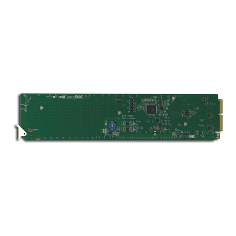
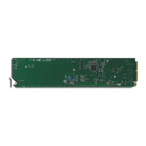
Ross SMA-8018 User manual

READ THIS FIRST!
Save Time and Avoid Damage!
We realize that you will want to start installing your new equipment right away. But, you will
save time and avoid costly damage by taking a few moments to review the following helpful
information before you proceed.
1. Installation and Cable Connections
Before turning the power on, consult the “Installation” section of this manual to
obtain specific advice about cable connections, switch settings and jumper
configurations.
2. Operation
See the “Operation” section for proper use of your new equipment.
3. Calibration
All Ross Video Terminal Equipment is factory calibrated. Adjustment of sealed
calibration components or any repairs to this unit, are to be performed by an
authorized Ross Video technician. Unauthorized repairs will void your Warranty.
In Case of Problems
If you encounter any problems with the installation of this unit, please call our Customer
Service Department at (613) 652-4886, 24 hours a day, 7 days a week.
Advice is available, without charge, for the life of this equipment, not just for the warranty
period.
DM-8018-02

SMA-8018
Serial Monitoring Amplifier
USER’S MANUAL
DM-8018-02

SMA-8018 •• Serial Monitoring Amplifier – User’s Manual
•Ross Part Number: DM-8018-02
•Document Issue: 2
•Printing Date: March 15, 2000. Printed in Canada.
The information contained in this guide is subject to change without notice or
obligation.
Copyright
© 2000 Ross Video Limited. All rights reserved.
Contents of this publication may not be reproduced in any form without the written
permission of Ross Video Limited. Reproduction or reverse engineering of
copyrighted software is prohibited.
Notice
The material in this guide is furnished for informational use only. It is subject to
change without notice and should not be construed as commitment by Ross Video
Limited. Ross Video Limited assumes no responsibility or liability for errors or
inaccuracies that may appear in this manual.
Trademarks
•is a registered trademark of Ross Video Limited.
•Ross, ROSS, ROSSand RossGear are registered trademarks of Ross
Video Limited.
•All other product names and any registered and unregistered
trademarks mentioned in this guide are used for identification purposes
only and remain the exclusive property of their respective owners.
Company Address
Ross Video Limited Ross Video Incorporated
8 John Street P.O. Box 880
Iroquois, Ontario, K0E 1K0 Ogdensburg, New York
Canada USA 13669-0880
General Business Office: (+1) 613 •652 •4886
Fax: (+1) 613 •652 •4425
Customer Service: (+1) 613 •652 •4886
Website: http://www.rossvideo.com
After hours emergency: (+1) 613 •652 •4886, ext. 333

SMA-8018 Serial Monitoring Amplifier
1-2
Introduction
The SMA-8018 Component Monitoring Amplifier provides a convenient and cost effective solution to
signal distribution and picture monitoring requirements in serial component (4:2:2) systems. The
complete unit occupies only a single card slot in a standard Ross digital rack frame. Ten modules may be
mounted in the 2-RU frame.
This equipment includes a 6 or 7 output serial distribution amplifier with re-clocking, as well as an
exceptionally good cable equalizer for the serial input to give error-free performance with up to 1000 ft
(305 meters) of 8281 cable. A component digital to analog composite converter provides 1 or 2 composite
analog monitoring outputs. NTSC or PAL monitoring may be selected.
The analog monitoring outputs can be set to monochrome if desired. In the absence of an input signal, a
color black monitoring output is produced. Moving a jumper to the TEST position can produce a 75%
color bar pattern. Vertical interval blanking width is jumper selectable for either normal width or narrow
width to allow the passage of all vertical interval signals.
Of special interest is the inclusion of an adjustable analog cable equalizer for the monitoring signal. This
can be set to equalize 8281 type of output cables of up to 300 ft (90 meters) in length thus ensuring that
the monitoring signal is delivered to the destination without chroma loss.
Indicators are provided to confirm adequate serial input signal strength and monitoring errors.
SMA-8018 Block Diagram

SMA-8018 Serial Monitoring Amplifier
1-3
Features
•Auto reclocking of serial digital input
•Input equalization for up to 1000 ft (300 meters) of cable
•Six or seven serial digital outputs
•One or two NTSC or PAL analog monitoring outputs
•Excellent chroma modulation accuracy
•Cable equalization for monitor outputs
•10 modules fit into a 2 RU frame
•Input level detection
Installation
1) Cables
Connect the input and output cables. The input is internally terminated in 75 ohms. The BNC
connectors on the rear of the frame are marked for distribution amplifiers having eight outputs.
However, in the case of the SMA-8018, there are six or seven outputs of serial digital and one or
two analog composite video outputs. It is not necessary to terminate unused outputs.
Refer to the following.
2) Set Jumpers
Set the jumper plugs to determine the nature of the analog output signal.
SYSTEM (JP2) PAL For 625 line systems
NTSC For 525 line systems
CHROMA (JP2) ON The normal position
OFF Used to output luminance only for the best picture on
a monochrome monitor.
SDl
Out 2
SDl
Out 4
SDI
Out 6
Analog
Out 1
SDI IN
SDI
Out 1
SDI
Out 2
SDI
Out 3
SDI Out 7/
Analog Out 2
7
2
4
3
6
5
8
IN
2
1
Cable Connections

SMA-8018 Serial Monitoring Amplifier
1-4
V BLANK (JP2) NORMAL Deletes all vertical interval information signals
(20-line blanking).
SHORT Passes all vertical interval signals occurring after the
post equalizing pulses. If setup is ON, the signal will
be non-standard because setup will be applied to the
vertical interval.
SETUP (JP2) ON For NTSC in North America
OFF For all other systems
MODE (JP2) NORMAL Normal operation
TEST Produces an analog color bar output. This may be
useful for monitor alignment.
OUT 7 (JP3) D Output 7 will have a serial digital output.
AOutput 7 will have a composite analog output.
FAULT REPORT (JP1)
DISABLE SMPTE 269M Fault Report is disabled.
ENABLE SMPTE 269M Fault Report is enabled.
3) Final User Setup
Set the analog output EQUALIZATION (RV2) adjustment for the cable length used between the
amplifier and destination. Plug the board into the frame and apply power.
The equalization control is calibrated for 8281 cable. For other types of cable, put the board on
the extender, apply a D1 color bar signal and using a scope, set the EQUALIZATION adjustment
for correct chroma level at the destination.
4) Check that the green INPUT STATUS LED is on and the MONITOR ERROR LED is off,
indicating a suitable input signal. The amplifier should be functioning properly.

SMA-8018 Serial Monitoring Amplifier
1-5
Operation
The only customer-operated controls are GAIN (RV4) and EQ (RV2) for the analog video output.
The GAIN control has been factory-adjusted for correct output level and should not need adjustment in
the field. The front edge of the module has several LED indicators, which show the current status of the
amplifier. The meaning of the LED indicators when lit is as follows:
INPUT STATUS
Green When lit means that the input signal is suitable for achieving error-free performance.
That is, it is within the capability of the cable equalizer and re-clocking circuit to
restore the signal.
Red This indicates that the input signal is too low or absent. In some circumstances the
signal may still be restored correctly but the circuits will be working close to the limit
of their capability and reliability cannot be assured.
MONITOR ERROR
This indicator identifies if there is a problem with the input signal or in the analog conversion
section of the card. There are three states for this indication.
STEADY RED The signal is present, but not the proper format (e.g. Composite
Digital). (During this condition, the SMA 8018 provides an
internally generated black burst signal to the analog outputs.)
FLASHING RED There is no input signal.
50% duty cycle (During this condition the SMA 8018 provides an internally
generated black burst signal to the analog outputs.)
FLASHING RED The monitoring amp is in the "TEST" mode.
10% duty cycle (In this mode the SMA 8018 provides an internally generated
color bar signal to the analog outputs.)

SMA-8018 Serial Monitoring Amplifier
1-6
Fault Reporting Capability
Fault reporting in the SMPTE 269M standard is available on this card. This is a simple system, which can
indicate that one, or more of the modules in the rack frame has encountered a fault or abnormal condition.
Each rack frame has a "telco" connector, which can be connected to an external "contact closure" type of
alarm system. A customer-devised system of lights can be used to trace a fault to a rack cabinet, rack
frame, then a particular card. For more information on designing such a system, refer to SMPTE
document ANSI/SMPTE 269M - 1994.
If the FAULT REPORT jumper (JP1) is enabled, the output will be a steady low signal if there is no
power in the module. The output will pulse at a field rate if the input signal is very low or absent. In all
other situations, the output is open (high impedance).
All frame modules having fault reporting capability are connected in parallel to the "telco" connector.
Maintenance and Repair
Routine maintenance is not required. If the module does not appear to be working properly, return it to
Ross Video Ltd. for repair. All Ross digital distribution products are covered by a generous 5-year
warranty and will be repaired without charge for materials or labor in this period. See "Ross Gear
Terminal Equipment - Warranty and Repair Policy" in this manual.

SMA-8018 Serial Monitoring Amplifier
1-7
Specifications Standard SMPTE 259M-C; 270 Mb/s 525/625 Lines
Input Impedance 75 Ω, terminating
Return loss > 22 dB to 300 MHz
Common Mode Rejection 4 V p-p @ 60 Hz
Serial Video Input
Equalization Automatic, up to 31 dB
Number of outputs 6 or 7 (jumper selectable)
Standard SMPTE 259M-C; 270 Mb/s 525/625 Lines
Output Impedance 75 Ω
Output return loss
Outputs 1-6 > 18 dB to 270 MHz
Outputs 7 > 17 dB to 270 MHz
Signal Level 800 mV ±10%
DC Offset 0 V (±0.5 V)
Rise & Fall Times 800 pS (±15%)
(20 - 80 %)
Serial Video Outputs
Overshoot < 8%
Number of outputs 1 or 2 (jumper selectable)
Output Impedance 75 Ω
Output return loss > 35 dB to 5 MHz
Output Isolation > 38 dB to 5 MHz
Signal Level 1V p-p ±5%
DC Offset < ±50 mV
Frequency Response ±0.05 to 4.2 MHz
-0.6 dB @ 5 MHz
Differential Phase < 0.8 degrees
Differential Gain < 1.8%
Group delay ±10 ns to 5.5 MHz
Analog Monitoring Outputs
RMS noise (unweighted) -54 dB 0 - 5.0 MHz.
Power Consumption 3.9 W
Specifications are subject to change without notification.
Ordering Information
SMA-8018 Serial Monitoring Amplifier
DFR-8104 Digital Products Frame (1 RU, Holds 4 modules)
DFR-8110 Digital Products Frame (2 RU, Holds 10 modules)
PS-8101 Power Supply (85-250 volts)
EXT-8100 Extender Board
DM-8018 Additional User's Manual for SMA-8018
Note: All Ross Video Limited terminal equipment frames include one power supply.
A redundant power supply may be installed in all two-rack unit frames if required.
One User's manual is supplied with each frame.

Ross Gear Terminal Equipment •• Warranty and Repair Policy
This Ross Gear Terminal Equipment product is warranted to be free of any
defect with respect to performance, quality, reliability and workmanship for a
period of FIVE (5) years from the date of shipment from our factory.
In the event that your Ross Gear product proves to be defective in any way
during this warranty period, we will gladly repair or replace this piece of
equipment with a unit of equal or superior performance characteristics.
Should you find that this Ross Gear product has failed after your warranty period
has expired, we will repair your defective piece of equipment for as long as
suitable replacement components are available. You, the owner, will bear any
labor and/or component costs incurred in the repair or refurbishment of said
equipment, beyond the FIVE (5) year warranty period.
Should your Ross Gear product be of our Digital Terminal Equipment product
line, a power supply, or carries any surface mount devices, proves to be
defective, we would ask that your piece of equipment be repaired by an
authorized Ross Video Limited factory representative. Any attempt to repair
this product by anyone other that an authorized Ross Video Limited factory
representative, will void your warranty.
If this is a manual for a Ross Gear product of our Digital Terminal Equipment
product line, a power supply, or piece of equipment which carries surface mount
devices, you will find it provides all pertinent information for the safe installation
and operation of your Ross Gear product.
If this is a manual for a Ross Gear product from our Analog Terminal
Equipment product line, you will find it provides all pertinent information for the
safe installation and operation of your Ross Gear product. Included in this
manual if this product does not carry any surface mount devices, you will also
find schematics, bills of materials and layout drawings. These are provided for
your convenience, should you find it necessary to perform discretionary field
repair or modifications to your Ross Gear product.
Ross Video Limited reserves the right to assess any modifications or repairs
made by you and decide whether they fall within warranty limitations, should you
decide to return your Ross Gear product for repair.
In no event shall Ross Video Limited be liable for direct, indirect, special,
incidental, or consequential damages (including loss of profits) incurred by the
use of this product. Implied warranties are expressly limited to the duration of
this warranty.
In Case of Problems:
Should any problem arise with your Ross Gear Terminal Equipment Product,
please contact our Customer Service Department at 613-652-4886, 24 hours a
day, 7 days a week.
A Return Material Authorization number (RMA) will be issued to you, as well as
specific shipping instructions, should you wish our factory to repair your Ross
Gear product. A temporary replacement, if required, will be made available for a
nominal charge. Any shipping costs incurred, will be the responsibility of you, the
customer. All products shipped to you from Ross Video Limited, will be shipped
collect.
Ross Gear Terminal Equipment product advice is available without charge for
the life of this equipment, not just the warranty period.
Table of contents
Other Ross Amplifier manuals

Ross
Ross CMA-8011A-7 User manual

Ross
Ross ADA-7802 User manual

Ross
Ross openGear SRA-8201A User manual

Ross
Ross VEA-8707A User manual

Ross
Ross CMA-8011A User manual

Ross
Ross ADA-7551 User manual

Ross
Ross UDA-8705A User manual

Ross
Ross openGear HDC-8222 User manual

Ross
Ross GearLite ADA-9503 User manual

Ross
Ross HDC-8223 User manual

Ross
Ross SEA-8008 User manual

Ross
Ross OpenGear HDC-8223A User manual

Ross
Ross TRA-8206 User manual

Ross
Ross SRA-8901 Series User manual

Ross
Ross ADA-8503 User manual

Ross
Ross OpenGear DRA-8902 Series User manual

Ross
Ross AMA-8511 User manual

Ross
Ross QRA-8808 User manual

Ross
Ross PC6400B User manual

Ross
Ross ADA-8501 User manual