Rossum LINNAEUS User manual

2 |
Contents
1. Introduction 3
2. Module Installation 4
3. Overview 5
4. Basic Functionality 7
5. Make Some Noise! 10
6. Main Filter Settings 12
7. Linear Filter Modulation 16
8. Ping Mode 18
9. Updating Software 21
10. From Dave’s Lab 23
11. Acknowledgements 24

| 3
1. Introduction
Thanks for purchasing (or otherwise
acquiring) the Rossum Electro-Music
Linnaeus Thru-Zero State Variable Filter. This
manual will give you the information you
need to get the most out of Linnaeus. The
manual assumes you already have a basic
understanding of synthesis and synthesizers.
If you’re just starting out, there are a number
of good reference and tutorial resources
available to get you up to speed. One that we
highly recommend is:
Power Tools for Synthesizer Programming
(2nd Edition)
By Jim Aikin
Published by Hal Leonard
HL00131064
Another great source of information is
Chris Meyer’s Learning Modular:
https://learningmodular.com
Support
In the unlikely event that you have a problem
with your Linnaeus, tell us about it here:
http://www.rossum-electro.com/support/support-request-form/
…and we’ll get you sorted out.
If you have any questions, comments, or just
want to say “Hi!,” you can always get in touch here:
http://www.rossum-electro.com/about-2/contact-us/
…and we’ll get back to you.
Happy music making!

4 |
2. Module Installation
As you will have no doubt noticed, the rear of
Linnaeus is a circuit board with exposed parts
and connections. When handling Linnaeus, it’s
best that you hold it by the edges of the front
panel or circuit board. It’s not particularly easy
to blow up, but why take chances?
More specifically, the biggest risk (to the extent
that there’s a risk), is damage by static electricity.
Particularly on dry, cold days (or if you’ve just
shued across your shag carpet in fuzzy
slippers), make a point of touching the metal
panel first, before touching any other part of
the module.
While all Rossum Electro-Music modules are
protected against reverse polarity damage,
both to your module and your system, care
should still be taken to connect the power
cable correctly. (For more detail on our
unique protection method, check out Dave’s
discussion of Circuit Protection in Chapter 10.)
Plug the included 16-pin connector into the
header on the rear of the module such that
the red stripe on the cable (the -12V side) is on
the same end of the header as the “Red Stripe
(-12V)” text on the PCB.
Linnaeus requires, at most, 155mA of +12V and
36mA of -12V.
We have included both M3 and M2.5 (for vector
rails) mounting screws. Use what fits your
system.
If rack rash is of concern to you, use the
included nylon washers when mounting
Linnaeus in your case.

| 5
3. Overview
What is Linnaeus?
Following in the tradition of
Evolution and Morpheus,
Linnaeus represents yet another
Dave Rossum innovation in filter
technology.
Linnaeus is a stereo state variable
filter that provides the unique
ability to linearly modulate its
resonant frequency through
zero into negative frequency,
while maintaining stability. With
extensive voltage control of nearly
every parameter, Linnaeus lets
you manipulate the filter’s natural
response curve in new ways, to
create both subtle and dramatic
timbral eects. And with a “one-
knob-per-parameter” interface,
Linnaeus inspires sonic creativity
that invites (and rewards) real-time
interaction.
Linnaeus’s cuto/resonant
frequency is exponentially voltage
controllable from subaudio to
ultrasonic frequencies, while its
resonant gain (Q) is exponentially
voltage controllable from 0dB to
greater than 60dB.
Linnaeus’s channel output
response characteristics are
independently and continuously
variable from Lowpass,
through Bandpass, Highpass
and Notch, to Low and High
Shelving. Voltage control of the
response characteristics can be
independently selected for each
of the two channels.

6 |
> An integrated modulation oscillator with
continuously variable waveform from
O through Sine, Triangle, Sawtooth and
Square. Its frequency can be exponentially
voltage controlled via an attenuverted CV
input.
> A Track control that lets the modulation
oscillator precisely track the filter’s
exponential frequency.
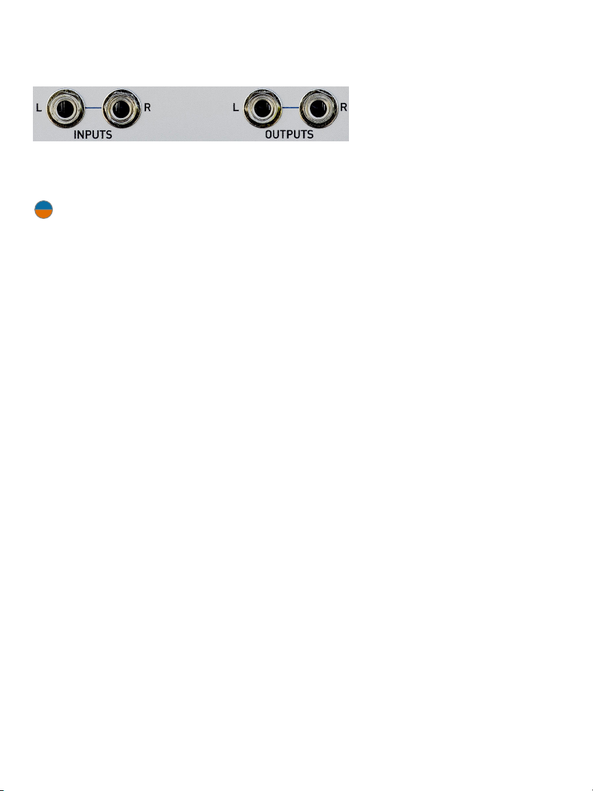
> Stereo inputs and outputs. Linnaeus
can process a stereo signal or two
independent mono signals. While the
two channels share the filter’s cuto/
resonant frequency, the filter response
characteristics can be independently
controlled for each channel.
> Linnaeus, like all Rossum Electro-Music
modules, features solid construction,
with thick aluminum panels, solid
aluminum knobs, and quality components
throughout.
What’s with the egg?
The Overview above describes Linnaeus as
originally conceived and designed by Dave.
However, late in the beta testing process,
our good friend and tester, Chris Meyer,
raised the possibility of alternative behavior
that would let Linnaeus function as a self-
contained (i.e., no input required) stereo
oscillator and/or percussion voice with some
really powerful timbral capabilities.
While we were initially hesitant to try to
shoehorn the new functions into the existing
interface, once Dave had prototyped them, it
was clear to us all that they were just too cool
not to include. So we’ve provided them in
the form of alternative firmware accessed by
pressing and holding the button.
See Chapter 8 for all the colorful details.
The linear thru-zero modulation is provided
by an integrated modulation oscillator and/or
an external linear FM modulation input.
The voltage-controllable modulation
oscillator can track the filter’s exponential
frequency or operate independently. The
modulation oscillator’s output waveform
is continuously variable from O through
Sine, Triangle, and Sawtooth, to Square. The
modulation oscillator output is summed with
the external linear FM input and input to the
modulation index VCA, which controls the
linear thru-zero modulation index from zero
to 8X. The modulation index is, of course,
also voltage controllable.
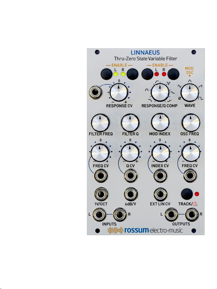
Linnaeus features include:
> Ultra-wide frequency range, exponentially
voltage-controllable from sub-audio
to ultrasonic via precise 1V/OCT and
attenuverted CV inputs.
> Thru-zero linear frequency modulation via
an internal modulation oscillator and/or an
external linear FM input.
> Variable linear modulation index, voltage-
controllable via an attenuverted CV input.
> Q (Resonance) exponentially voltage-
controllable from 0dB to greater than
60dB via 6dB/V and attenuverted CV
inputs.
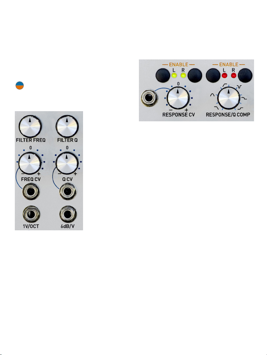
> Continuously variable response
characteristics independently selectable
for each of the two channels via individual
Response Enable controls. Characteristics
include Lowpass (12dB/oct and 6dB/oct),
Bandpass, Highpass (12dB/oct and 6dB/
oct), Notch, and Low and High Shelving.
> Voltage control of response characteristics
via an attenuverted CV input. Individual
Response CV Enable controls let you
independently enable or disable CV
control of response for each channel.

| 7
4. Basic Functionality
Before we jump into individual functions in
detail, let’s take a quick look at Linnaeus’s
controls.
NOTE: The control functions described
below reflect the main Linnaeus firmware.
Check out Chapter 8 for the alternate control
functions in Ping Mode.
FILTER FREQ
Controls the
filter’s initial
cuto frequency
over a range
exceeding 20Hz
to 20kHz.
FREQUENCY
CONTROL
INPUTS
Calibrated 1 volt
per octave and
attenuverted
exponential CV
inputs.
FILTER Q RESONANCE
Sets the filter’s resonance from 0dB to over
60dB.
Q CONTROL INPUTS
Calibrated 6dB per volt resonance CV input
and attenuverted CV input.
FILTER RESPONSE/Q COMP
Selects the filter channels’ initial response
characteristics. The response is continuously
variable between Lowpass (12dB/oct and
6dB/oct), Bandpass, Highpass (12dB/oct and
6dB/oct), Notch, and Low and High Shelving
and is independently selectable for each of
the two channels via the individual Response
Enable controls.
When both the Response Enable controls are
o, the control sets the amount of level
compensation for the current Q.
RESPONSE CV
The attenuverted CV input can be individually
enabled for each of the two channels. The
Response CV Enable buttons also allow you
to select the polarity of the control for each
channel.

8 |
MOD INDEX
LINEAR MOD INDEX VCA
Sets the degree to which the
internal Modulation Oscillator
plus the External Linear
CV input aects the filter
frequency. The modulation
index can be set to values
from 0 to 8x.
INDEX CV MODULATION
INDEX CONTROL INPUT
An attenuverted CV input.
EXT LIN CV
Full-level input that is added
to the output of the internal
Modulation Oscillator to
linearly control the filter’s
frequency.
MODULATION
OSCILLATOR WAVE
Selects the output wave
of the internal Modulation
Oscillator. Continuously
variable from O through
Sine, Triangle, Sawtooth and
Square.
MOD OSC FREQ
Controls the Modulation
Oscillator’s frequency over a
range of 20Hz to 20kHz.
FREQ CV MOD OSC
FREQUENCY CV INPUT
An attenuverted exponential
CV input. Maximum range is
+/- 1 volt per octave.
TRACK
Press to engage (LED lit) Mod
Oscillator Tracking. When
engaged, the Mod Oscillator
precisely tracks the filter’s
exponential frequency. Press
and hold, or double click, to
engage the alternate “Ping
Mode” functionality described in Chapter 8.
The LED will flash. Double click toggles Ping
Mode on and o.

| 9
INPUTS & OUTPUTS
Stereo, DC coupled inputs and outputs. 20V
p/p max level. The left input is normalled to
the right input.
NOTE: Linnaeus can process a stereo
signal or two independent mono
signals. While the two channels share the
filter’s cuto/resonant frequency, the filter
response characteristics can be independently
controlled for each channel.

10 |
5. Make Some Noise!
While we highly encourage you to read
this complete manual (you don’t want to
inadvertently miss out on any capabilities),
spending a few minutes here will give you a
quick introduction to the function and eects
of the basic controls.
Given Linnaeus’s complement of knobs and
mod inputs, experimentation is the order of
the day. To get you started:
Basic Filter Settings
> Patch some harmonically rich audio into
the input(s). If you’re using a mono signal,
connecting it to the left input will cause
it to be normalled to the right input as
well — allowing you to experiment with
selecting dierent response characteristics
for the two channels.
> Press the Response CV Enable buttons
above the Response CV knob until both
LEDs are green. This turns on positive
polarity CV Response control for both
channels.
> Press the Response Enable buttons above
the Response knob until both LEDs are
red. This allows the Response knob to
select the response characteristic of both
channels.
> Set the Mod Oscillator Wave parameter to
O.
> Turn the Response knob fully
counterclockwise to select 12dB/oct
lowpass.
> Adjust the Filter Frequency knob and listen
to the result.
> Adjust the Filter Q knob while adjusting
the Frequency knob and listen to the
result.
> Use the Response knob to select dierent
response characteristics and repeat the
two previous steps.
> With a stereo or normalled mono input,
select a Response characteristic. Then
press the Right Response Enable button
to turn o its associated LED. Select a
dierent Response characteristic. This
new response will be applied to the left
input while the right input will remain
assigned to the initially selected response.
Adjust Frequency and Q and listed to the
eect.
Basic Modulation
> Patch CVs into some or all of the
Response CV, 1V/Oct, Freq CV, Q CV, and/
or 6dB/V inputs. Adjust attenuverters.
Listen to the results.
> While modulating Response, press the
channel Response CV Enable buttons to
cycle between positive modulation (green
LED), negative modulation (red LED), and
no modulation (LED o). Listen to the
eect of various combinations.
Thru-Zero Linear Frequency
Modulation
There are innumerable possibilities for linear
FM patches, but here’s one that gives a good
introduction to a basic approach.
> Patch a low frequency (~1Hz) sawtooth
into the input.
> Turn up Q quite high so that you hear
ping, ping, ping.
> Select 12 dB lowpass response and set the
Filter Freq to a mellow timbre.
> Turn up the Mod Index and carefully tune
the Mod Oscillators Freq for a pleasing
sound (typically a fifth or octave above the
filter’s resonant frequency).
> Adjust the Mod Index and listen to the
range of timbral variation.

| 11
> Turn on Mod Oscillator Track (if it isn’t
already on) and adjust filter frequency. The
inherent timbre should remain consistent
as the pitch of the ringing changes.
> With the same settings, try dierent input
audio and Q settings and note the results.
Thru-Zero Linear Frequency
Modulation Modulation (brought
to you by The Department of
Redundancy Department)
> Patch CVs into the Index CV and/or Mod
Osc Freq CV inputs. Adjust attenuverters.
Listen to the results.
> Patch a CV (up through audio range) into
the External Linear CV input. It will be
added to the Mod Oscillator output (unless
the Mod Oscillator is set to O, in which
case it will provide the sole modulation).
Adjust the various parameters and listen to
the results.
NOTE: The above suggestions apply to the
normal firmware. For the alternate Ping
Mode, see Chapter 8.

12 |
6. Main Filter Settings
FREQ CV
The Freq CV input is an
exponential control voltage
input that is modified by its
associated attenuverter and
then summed with the value
of the Filter Freq control
and the 1V/OCT input to
determine the final frequency.
When the attenuverter knob
is set to its “0” position, no
control voltage is passed to Linnaeus. As
the knob is turned clockwise from 0, the
amplitude of the control voltage increases
until, at maximum clockwise rotation, the full
amplitude of the signal at the Freq CV input
is passed through and results in a nominal 1V/
Oct response.
As the knob is turned counter-clockwise from
0, the signal at the Freq CV input is inverted
(e.g., a CV of +2.5V becomes -2.5V). The
farther counterclockwise the knob is turned,
the less the attenuation of the inverted signal,
until, at maximum counterclockwise rotation,
the full amplitude of the inverse of the signal
at the Freq CV input is passed through, also
at a nominal 1V/Oct response.
1V/OCT CV
The 1V/OCT CV Input is a
calibrated full level exponential
control voltage input that is
summed with the values of the
Filter Freq control and the Freq
CV input to determine the final frequency.
FILTER Q RESONANCE
This control lets you set the filter’s
initial resonance from 0dB to over
60dB.
At its core, Linnaeus is a superb state
variable filter. In this chapter, we’ll look at the
main filter and modulation settings. In the
following chapter, we’ll look at its unique
thru-zero modulation functions.
INPUTS
Linnaeus’s two
independent inputs
are DC coupled (so
you can process CVs)
and will accept a
maximum level of 20V p/p.
The left input is normalled to the right input.
Plugging a single input into the left input is
functionally equivalent to multing the input
and plugging it into both the left and right
input.
NOTE: Linnaeus can process a stereo
signal or two independent mono
signals. While the two channels share the
filter’s cuto/resonant frequency, the filter
response characteristics can be independently
controlled for each channel.
FILTER FREQ
This control lets you set the
filter’s initial frequency over a
range of 20Hz to 20kHz.

| 13
Q CV
The Q CV input is an
exponential control voltage
input that is modified by its
associated attenuverter and
then summed with the value
of the Filter Q control and the
6dB/V input to determine the
final resonance.
The attenuverter functions as
described above. Its extreme
clockwise and counterclockwise settings
provide a nominal response of 2x/V. A
change in CV of one volt will result in either
doubling or halving the resonance.
6dB/V
The 6dB/V CV Input is a calibrated
full level exponential control
voltage input that is summed with
the values of the Filter Q control
and the Q CV input to determine
the final Q value. As a change
of 6dB results in doubling or halving the
resonance, each volt at this input will double
or halve it.
RESPONSE/Q COMP
When one or both of
the Response Enable
LEDs are on, this
control lets you select
the initial filter response
characteristic for one
or both of the two
channels.
The response for
each channel is
continuously variable between (in clockwise
order from fully counterclockwise) 12dB/oct
lowpass, 6dB/oct lowpass, bandpass, 12dB/
oct highpass, 6dB/oct highpass, notch, low
shelving, and high shelving.
The response is independently selectable for
each of the two channels via the individual
Enable controls described below.
NOTE: While the control has blue tick marks
surrounding it (implying discreet settings),
the response actually transitions smoothly and
continuously from one response to another.
The pure bandpass and notch responses are
found at their specific tick marks, but the rest
of the response indicators indicate a range of
lowpass, highpass and shelving responses.
RESPONSE ENABLE
The Response Enable buttons and associated
LEDs let you set which of the two channels
(or both) will respond to changes of the
Response control.
Repeatedly pressing a channel button will
toggle between enabled (LED on) and
disabled (LED o).
When a channel is enabled, adjusting the
Response control will set the response of that
channel.
When a channel is disabled, the channel
maintains the most recently selected response
and will ignore changes to the Response
control.
In practice, this lets you set each channel to
a dierent response. So, for example, if you
want to set the left channel to lowpass and
the right to notch:
>Press the Left Response Enable button
until the left channel is enabled (LED on).
(At this point, it doesn’t matter if the right is
enabled or not).
>Use the Response control to select the
lowpass response of your choice.
>Press the Left Response Enable button to
disable the left channel (LED o). It will now
maintain the selected lowpass response.
>Press the Right Response Enable button
until the right channel is enabled (LED on).
>Use the Response control to select notch.
When both Response Enable controls are o,
the control sets the amount of level compen-
sation for the current Q, as described next.

14 |
RESPONSE CV
The Response
CV input is a
control voltage
input that is
modified by
its associated
attenuverter and
then summed
with the value
of the Response
control to determine the final response.
RESPONSE CV ENABLE
The Response CV Enable buttons and
associated LEDs let you select which of
the two channels (or both) will respond to
voltages at the Response CV input.
Repeatedly pressing a channel button will
cycle between disabled (LED o), enabled
with positive polarity (green LED), or enabled
with negative polarity (red LED).
In practice, this lets you:
>Modulate both channels in the same
direction
>Modulate both channels in opposite
directions
>Modulate one channel, but not the other
>Modulate neither channel
A TIP: With a stereo input, try setting both
channels to the same response and
setting the Response CV Enables to opposite
polarities. Patch a slow sine or triangle into the
Response CV input and listen to the resulting
timbral eect as the two channels briefly share
responses as the CV passes through 0 volts
and then vary in opposite directions as the CV
moves above and below 0. Try adjusting the
filter frequency and initial response.
Q COMPENSATION
When both Response
Enable controls are o,
the Response/Q Comp
control sets the amount
of level compensation
for the current Q.
Linnaeus is capable of providing an extremely
high level of resonance. As previously
mentioned, its maximum resonance is in
excess of 60dB, compared to the maximum
resonance of 24dB before self-oscillation of
our Evolution ladder filter.
NOTE: Unlike Evolution, Linnaeus (as is
typical for state variable filters) will never
enter self-oscillation.
As a result, setting the filter frequency to
the fundamental or first few harmonics
of an input signal and cranking up the Q
will often result in overdrive distortion.
Now, while Linnaeus oers really tasty soft
clipping distortion, that may not always be
what you want. For those cases, we have Q
Compensation.
Q Compensation lets you set the amount
of level attenuation applied to the input
as a result of the current resonance. The
higher the resonance, the more the level
attenuation. The Response/Q Comp control
lets you select the ratio between increases in
Q and input attenuation.
As examples:
>With the control fully counterclockwise,
there will be no Q compensation.
Increasing Q will have no eect on input
level.
>Setting the knob at about 11:00 o’clock
results in what we have found to be a
reasonable default value. Increasing
Q results in a moderate amount of
attenuation. This is the value that is set at
the factory for new Linnaeuses.
>Setting the knob fully clockwise results in
maximum compensation and will tame
most high Q settings.

| 15
NOTE: If, when you turn o both Enable
controls, the Response/Q Comp knob is
at a position that does not correspond to the
current Q Compensation setting (as will often
be the case if you’ve been using the control
to select Response), the Q Compensation
setting will not immediately jump to the setting
associated with the knob position. However,
once you turn the knob, the setting will then
move to reflect the knob’s position.
ANOTHER NOTE: The same behavior
described above also applies to the
situation where the Response knob has been
disabled for a channel and then later re-
enabled. The Response setting will not jump to
a new value until the knob is slightly moved.
IMPORTANT NOTE: Q Compensation
is not only for completely eliminating
distortion. If some distortion is what you want,
Q Compensation provides a method to dial
in just how much of that distortion you’d like.
As such, it can operate as a powerful creative
control.

16 |
7. Linear Frequency Modulation
As we said in the previous chapter, Linnaeus
is, at its core, a superb state variable filter. But
its thru-zero linear FM capability truly sets
it apart in the world of modular (or, in fact,
any) filters. It opens up exciting new timbral
possibilities that are simply not attainable with
exponential modulation.
It’s beyond the scope of this manual to
provide an in-depth discussion of exponential
versus linear versus thru-zero linear FM, but
for those interested, Chris Meyer (as part
of his Learning Modular series) oers clear
explanations, along with audio examples,
here:
https://learningmodular.com/
understanding-the-dierences-between-
exponential-linear-and-through-zero-fm/
Of course, Chris’s explanation focuses on
oscillators, since when he wrote it, there were
no thru-zero linear FM filters, but it still does
a great job of making the dierences easily
understandable.
NOTE: In addition to its External Linear CV
input, Linnaeus also provides the ability to
linearly modulate its frequency via its internal
Modulation Oscillator. Using this oscillator,
you have access to an extremely wide range
of timbres without the need of patching an
external CV. (Of course, adding in an external
CV further expands the possibilities.)
MOD INDEX
The Mod Index is a linear
control that sets the initial
value of the internal Linear
Mod Index VCA that defines
the degree to which the sum
of the output of the internal
Modulation Oscillator and the External
Linear CV input aects the filter frequency.
The mod index range is from 0–8x.
INDEX CV
The Index CV input is a
control voltage input that is
modified by its associated
attenuverter and then
summed with the value
of the Mod Index control
to determine the final
modulation index.
A TIP: Modulating the modulation index
is a powerful tool for creating dynamic
timbral variation. Experiment with both LFO
range and audio rate modulation sources, as
well as a variety of modulation waveforms.
EXTERNAL LINEAR CV INPUT
This is a full-level input that
is added to the output of the
internal Modulation Oscillator
to linearly control the filter’s
frequency. It will accept a
maximum level of 20V p/p.
MOD OSCILLATOR WAVE
This control selects the output
wave of the internal Mod
Oscillator. It is continuously
variable from O through
Sine, Triangle, Sawtooth and
Square. As you move the
control from O to Sine, the
sine wave will smoothly fade
in. As you continue turning the
knob, the output will smoothly
morph between the adjacent waves.

| 17
OSC FREQ
This control lets you set the
Modulation Oscillator’s initial
frequency over a range of 20Hz
to 20kHz.
FREQ CV
The Freq CV input is an
exponential control voltage
input that is modified by its
associated attenuverter and
then summed with the value
of the Osc Freq control to
determine the final Mod
Oscillator frequency.
With the attenuverter
in the full clockwise or
counterclockwise positions, the modulation
response is a nominal 1V/Oct.
TRACK
Press this button to engage
Mod Oscillator tracking. When
engaged, the associated
LED will be lit and the Mod
Oscillator will precisely track
the filter’s exponential frequency.
A TIP: If whatever is supplying your input
audio has a 1V/Oct frequency input, try
using the same frequency control CV into
both the input’s and Linnaeus’s 1V/Oct inputs.
Enable Track and iteratively adjust Linnaeus’s
frequency and the Mod Oscillator’s frequency
for the timbre of your choice. You can now
use the frequency control CV to drive the
frequency of both the input and Linnaeus in
parallel while maintaining your chosen timbre.
NOTE: Although we won’t be discussing
the alternate Ping Mode until the next
chapter, it’s probably worth noting here (in
case you accidentally do it) that pressing and
holding, or double clicking, the Track button
will activate Ping Mode. The LED will flash to
indicate this. Double click the button to toggle
Ping Mode on and o.
A TIP: If you don’t press Track on
Linnaeus, but have the Mod Osc patched
through its frequency attenuverter to track
the incoming signal, and now vary the filter
frequency, you will also get interesting eects.
Try it!

18 |
8. Ping Mode
As mentioned back in Chapter 3, late in
the beta testing process, our good friend
and tester, Chris Meyer, suggested some
alternative behavior that would let Linnaeus
function as a self-contained (i.e., no input
required) stereo oscillator and/or percussion
voice with some really powerful timbral
capabilities.
Once we realized how cool that was, our
main dilemma was how to integrate the
new functions into an existing interface that
had not been designed with them in mind.
We eventually decided that providing them
as a built-in “alternate firmware” was least
disruptive to the core interface.
And thus was born the
Track/ button!
Of course, you could patch this manually
using the main Linnaeus functionality
and a number of additional modules, but
by integrating a dedicated internal “ping”
oscillator, and providing some very useful
internal patching options, a variety of creative
timbral capabilities are provided without the
need for complex external patching.
When in Ping Mode, a dedicated internal
sawtooth oscillator is applied to the Left
and/or Right channel. Alternatively, you can
set one or both channels to “manual” ping
mode. In manual ping mode, pressing the
Left or Right Response CV Enable buttons
will trigger a pulse to the corresponding
input, as will triggers or gates (or, in fact, any
audio) patched to the corresponding audio
input(s).
Ping Mode is typically used by choosing
a setup (see below), then tuning the Mod
Oscillator and Wave to create an interesting
timbre, which can then be modulated by the
Modulation Index and more subtly by the
filter Response.
Enabling Ping Mode
Pressing and holding, or double clicking, the
Track/ button will activate Ping Mode. The
LED will flash to indicate this. Double-clicking
the button will toggle Ping Mode on and o.
NOTE: In Ping Mode, the Track LED will still
indicate whether or not Mod Oscillator
Tracking is engaged. If tracking is not engaged,
the LED will flash on with a brief red flash.
If tracking is engaged, the LED will be red and
will flash o briefly.
NOTE: We realize that the interface
described below is not as elegant as it
would be in a module we designed specifically
for this functionality, but we’re pretty sure that
you’ll find the creative possibilities that it opens
up are more than worth it.
So what is Ping Mode?
Ping Mode is an optional functional mode for
Linnaeus that allows it to be used as a sound
source (oscillator) without the need for any
signal at its audio inputs. It takes advantage
of the fact that at high Q levels, “pinging” the
filter with a sharply rising waveform will cause
the filter to ring at its resonant frequency. The
higher the Q, the longer the filter rings. If the
filter is pinged at audio rate (or at least often
enough that the sequential ringing overlaps),
the filter will generate a continuous signal,
essentially becoming an oscillator.

| 19
Ping Mode Setup
Pressing and holding the Track/ button
will allow you to view and adjust the various
Ping Mode setup options. While the button
is held, you can control the frequency of the
Ping Sawtooth Oscillator, whether it tracks
the Filter Frequency or the Mod Oscillator
Frequency, whether it is applied to the Left
or Right Channel, or both, and whether a
channel will be pinged by the Ping Oscillator,
a manual button press or external input, or
nothing.
Viewing Setup Options
NOTE: In the following instructions, be
sure to carefully dierentiate between the
Response CV Enable buttons and LEDs (above
the Response CV knob) and the Response
Enable buttons and LEDs (above the Response
knob). As the only dierences are the “CV,” it
can be easy to get mixed up, which can have
disconcerting results.
While the Track/ button is held:
The Left and Right Response CV Enable
LEDs will indicate which channels will receive
a ping:
>If the LED is o, the channel will not be
pinged.
>If the LED is green, the channel will be
continually pinged by the internal Ping
Oscillator and the Ping Oscillator will track
the Filter Frequency.
>If the LED is red, the channel will be
continually pinged by the internal Ping
Oscillator and the Ping Oscillator will track
the Mod Oscillator Frequency.
NOTE: While in red/green Internal Ping
Mode, the audio inputs also remain active,
and any signals present there are added to the
pings.
>If the LED is blinking yellow, it can
be manually pinged by pressing the
associated Response CV Enable button.
NOTE: While in manual Ping Mode,
triggers or gates (or, in fact, any audio)
patched to the corresponding audio input(s)
will also generate pings.
Adjusting Setup Options
While the Track/ button is held, the top
row of Response Enable buttons control the
Ping setup as follows:
>Pressing the Left Response Enable button
causes the Ping Oscillator to track the filter
frequency. The Response CV Enable LED
of any channel set to Internal ping will light
green
>Pressing the Right Response Enable
button causes the Ping Oscillator to
track the Mod Oscillator frequency. The
Response CV Enable LED of any channel
set to Internal ping will light red.
>Pressing the Left Response CV Enable
button determines, cyclically, the ping
source of the left channel: O, Ping
Oscillator, or Manual/External.
>Pressing the Right Response CV Enable
button determines, cyclically, the ping
source of the right channel: O, Ping
Oscillator, or Manual/External.
NOTE: You cannot turn both channels o
simultaneously. If one channel is set to o,
pressing the button of the other channel will
cycle only through internal and manual ping.
To turn both channels o simultaneously, exit
Ping Mode.
>Adjusting the Mod Oscillator Wave knob
will select the Ping Oscillator frequency
ratio. The available frequencies are
fractional integer ratios of the selected
frequency source (i.e., filter frequency
or Mod Oscillator frequency). The ratios
range from 1/32 to 1. The default ratio is
1/4 (i.e., the Ping Oscillator will run at 1/4
the frequency of its selected frequency
source).

20 |
NOTE: If you have selected the Mod
Oscillator as the Ping Oscillator frequency
source, and Mod Oscillator Track is enabled,
adjusting the Mod Oscillator frequency will,
as expected, change the frequency of the
Ping Oscillator. However, changing the filter
frequency will also change the frequency of
the Ping Oscillator, as it will change the Mod
Oscillator frequency which will, in turn, change
the Ping Oscillator frequency. If you do not
want the filter frequency to aect the Ping
Oscillator, be sure Track is o.
ANOTHER NOTE: Once a ping setup has
been programmed, it will be remembered
the next time Ping Mode is activated, even
through a power cycle.
Ping Mode Operation
All of the above describes the behavior while
the Track/ button is held down.
Releasing the Track/ button returns the
LEDs and controls to their usual functions,
with the following exceptions:
> If a channel is in Manual Ping Mode, its
Response CV Enable button will trigger a
manual Ping on that channel rather than
toggling the Response CV assignment.
To show this state, the associated
Response CV Enable LED will blink yellow
superimposed on the color of the current
Response CV Enable assignment.
NOTE: Since you can’t change the
Response CV Enable assignment of a
channel assigned to Manual Ping Mode while
in Ping Mode, it’s easy simply to exit Ping
Mode, use the Response CV Enable button to
change the assignment, and then re-enable
Ping Mode.
> Any signal at the input of a channel
assigned to Manual/External Ping Mode
will be converted to triggers which will
ping the filter.
A TIP: Patch the output of a gate or trigger
sequencer to the input of a channel in
Manual/External Ping Mode to use Linnaeus as
an FM percussion synth voice. With this setup:
>Filter Frequency controls tuning.
>Qcontrols decay.
>Mod Index + Mod Oscillator Frequency +
Mod Oscillator Wave control modulation,
and therefore, timbre.
As Chris Meyer pointed out
in our discussions of this,
“If someone loves ‘Buchla
Bongos,’ here they are in
one module.”
ANOTHER TIP: We have found it easier to
dial in tones in Internal Ping Mode if the
Ping Oscillator is set to track the Mod Oscillator
rather than filter frequency. When ping rate
tracks the filter frequency, it can be tricky to
dial in Mod Oscillator Frequency settings that
are in tune or otherwise consonant. Settings
are more forgiving when ping rate tracks the
Mod Oscillator, so we would suggest that as
a starting point when first experimenting with
Internal Ping Mode.
YET ANOTHER TIP: In Manual/External Ping
Mode using an external audio rate signal,
the relationship between filter frequency and
the external signal source’s tuning is very
important. Once you get them aligned to
where, for example, filter frequency is tuned to
a harmonic of the external signal source, the
amplitude goes way up and it’s more viable as
an oscillator. To maintain this consistent timbre,
control the frequencies of both the external
signal source and Linnaeus with the same full
level CV.
Table of contents
Popular Water Filtration System manuals by other brands

Viessmann
Viessmann Vitopure S2-2T Manual book

Krohn-Hite
Krohn-Hite 3380 Series operating manual

Millipore
Millipore Milli-Q Direct 8 System user manual

Flowmatic
Flowmatic FMRO5-M-MT Installation, operation and maintenance manual

AQUARIUS
AQUARIUS AD18 installation guide

ACO Haustechnik
ACO Haustechnik LipuSmart-P User instructions