Rl s·
Tower
Speaker
Installation
Instructions
(x2)
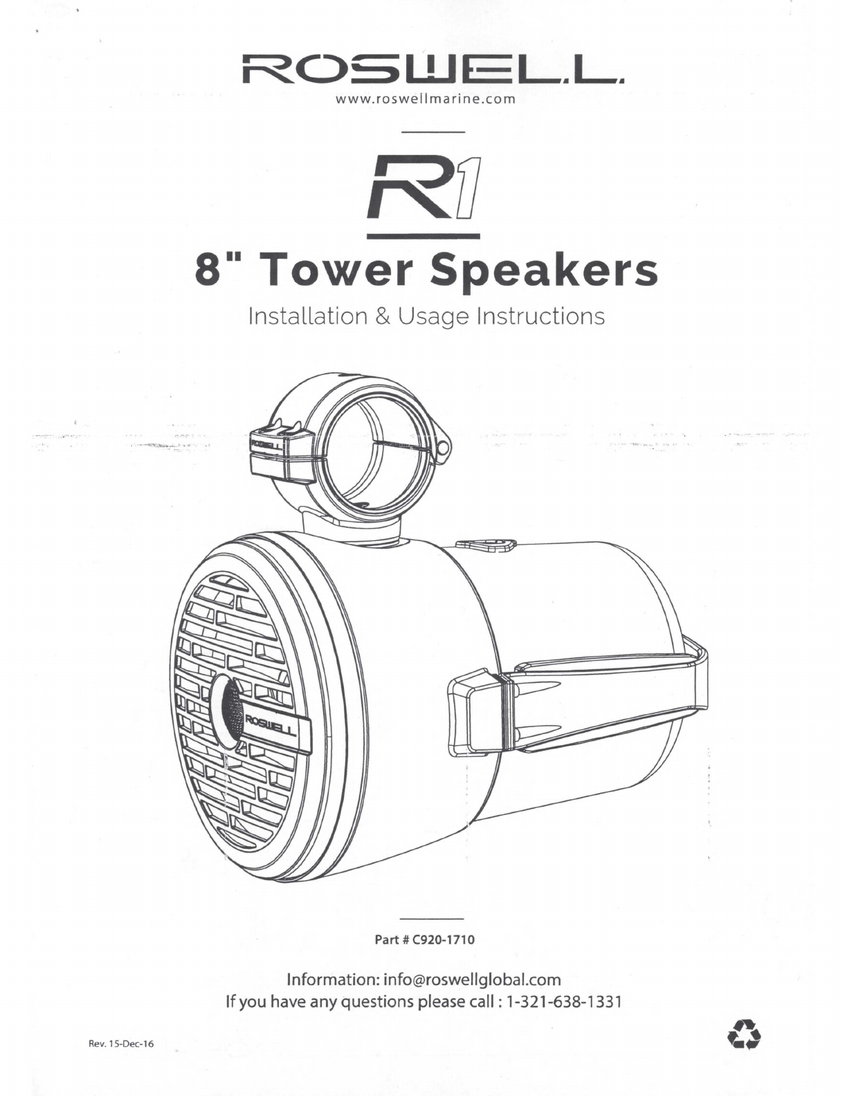
Rl 8" Tower
Speakers
Preparation
PACKAGE CONTENTS .
(x2)
(x2)
Wiring Safety
Harness Lanyard
(g)
© g
~ij
.
x2 x4 x12
Tower and boatWiring (not includedi
www
.
roswellmarine
.
com
TOOLS &·SUPPLIES NEEDED ·
r r
~
,
(Q
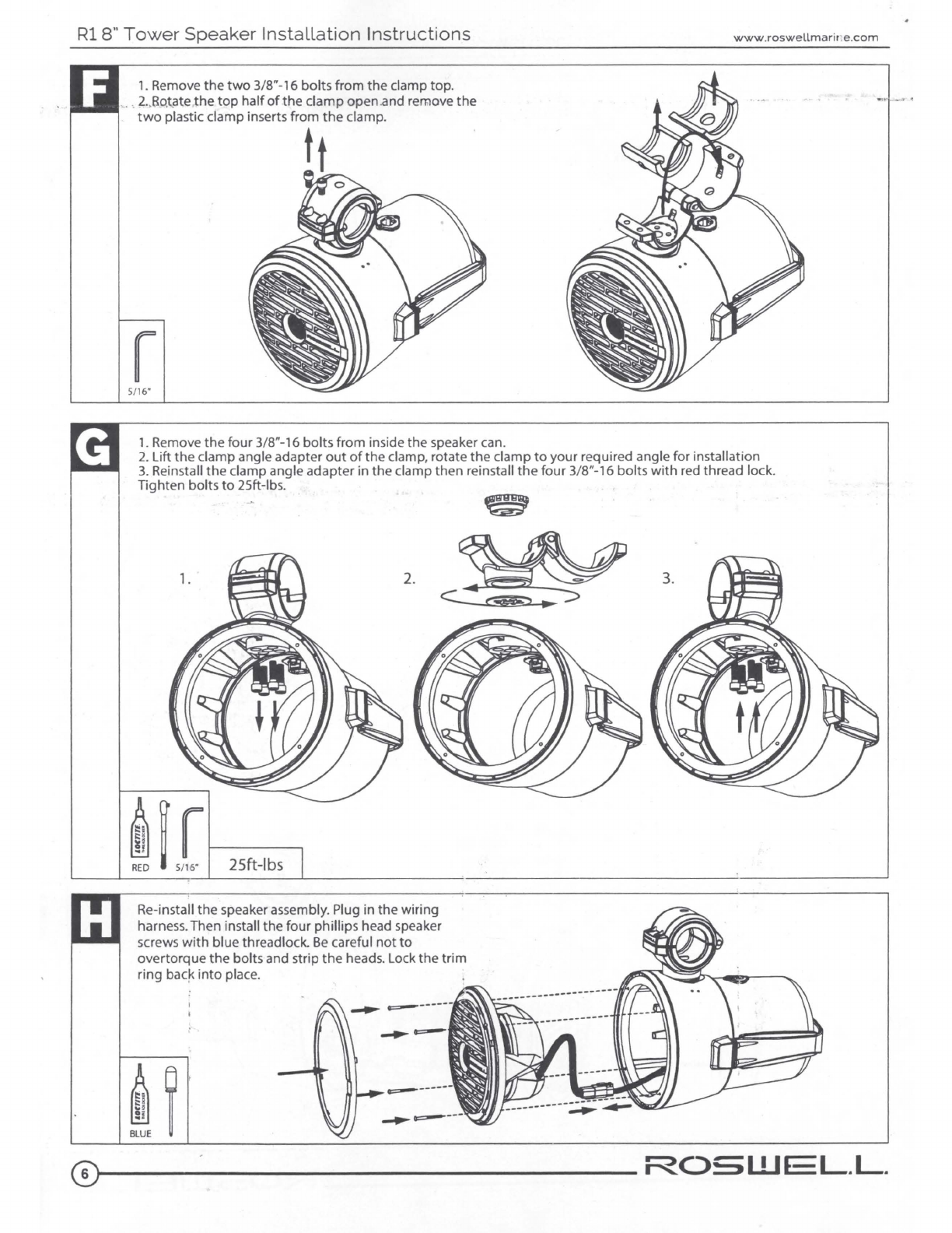
3/32' Allen
Key
Torque Utility Measuring
5/
16
' Allen
Key
Wr
ench Knife
Hea
t Gun
Tape
~
~; ~; i
i:::
8
i:::
g
"'~
"'~
0~
0~
.,.
!
...
i
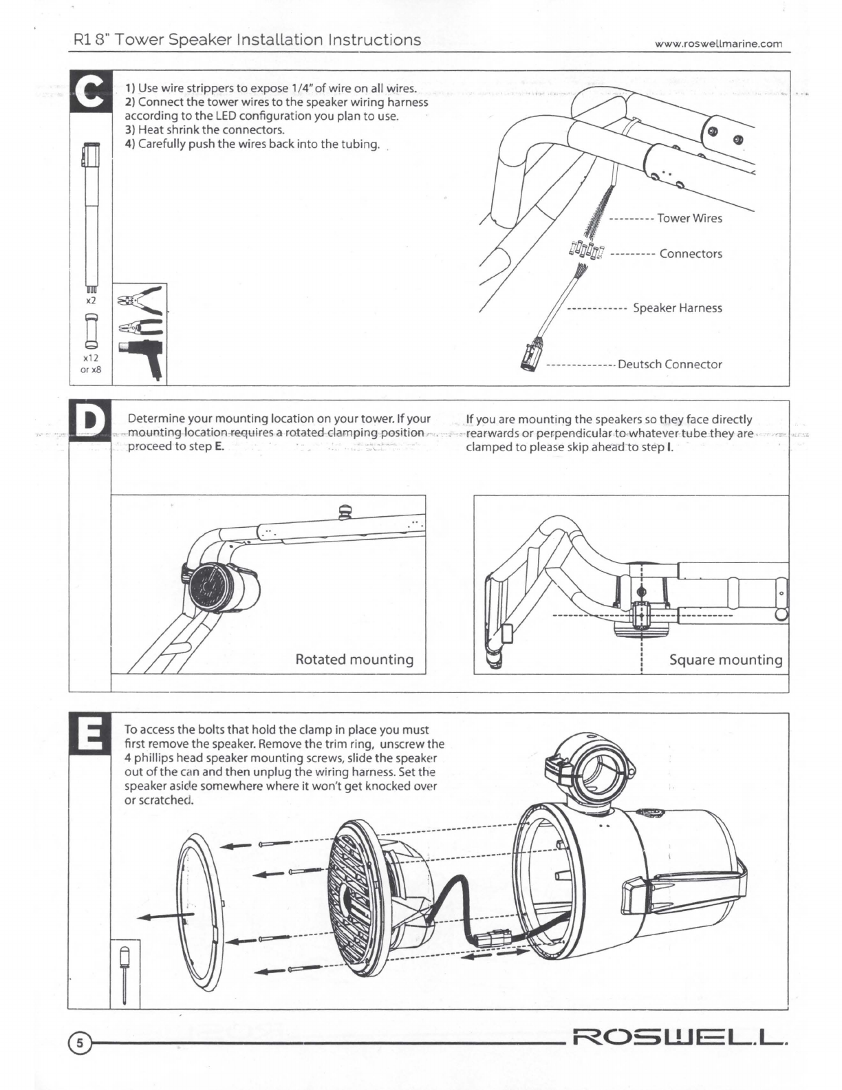
Wire Strippers Phillips
Sc
rew
&Crimps
RED
BLUE
Driver
• For safety,
turn
off
the
audio system and battery switch prior
to
begi
nning
installation.
If
your
vessel
does
not
have a
battery
switch,
simply disconnect the positive lead from the batteryterminal.
, •.
l;)se
extrerrie caution before cutting
an
_d drilling holes
to
avoid damaging fuel lines, hydraulic lines,
or
existing electrical
components
.
• Avoid running wires near sharp edged surfaces. Never run wires exposed on thedeck,protecting thewires with acover offers
the
best
protection from marine elements.
If
wires must
be
routed through metal or fiberglasswalls,
use
rubbergrommets to protect
the
wire.
•Roswell recommends using
16
gauge wire for
the
audio connections and
18
gauge wire for the 12-volt
LED
connections.
•
You
will need
to
supply a length
of
positive and negative
16
gauge speaker wi
re
to
run from your speaker
mounting
locations
to
your
amp
or
head
unit
.Connections
to
either
an
amp
or
head
unit
are
your responsibility
to
provide.
12-Volt
LED
Wire (not included)
• Note: Consider
how
you would like
to
use
the integrated
RGB
LED
before you begin installation.It can either be hard-wired
to
one
of
7 different colors or you may purchase
an
LED
controller
to
allow any combination
of
colors and patterns
(see
next page
for
details).
•
If
you are hard-wiring
the
RGB
LED's
on these speakers, you will need
(1)
18
gauge power and
(1)
18
gauge ground wire
from
the
speaker
mounting
locations
to
your power source.
•
If
you are using an
RGB
LED
controller, you will need
to
run
(1)
18
gauge power and
(3)
18
gauge ground wires from
the
speaker
mounting
locations
to
your
LED
controller.Refer
to
the
RGB
LED
controller instructions for further information.
Positioning
•We suggest
mounting
your speakers on the rear crossbar
of
your
tower
facing backwards.Many people posi
tion
them
further
to
the
sides
of
the
tower
to
have more headroom when moving around inside
the
boat.
Wire Routing
•Consider
how
you will route your wires before you begin your installation.
It
is
generally best
to
keep audio and power wires
separate whenever possible.In towboats, wiring for
tower
speakers
is
typically done along the
port
side
as
your boat's
battery
is
easily accessible and the observers/judges seat storage area offers more space for your amp.
•Because each boat and tower setup
is
different, there
are
no specific instructions for wiring the
tow
tr
r - generally most
people
will
run
the
wires internallythrough their tower.
To
do
thisyou will need
to
drill aseries
of
holes that wil~allow you
to
run
the
wiring
harness inside
the
tower
to
your desired
mounting
lo~.ation.
You
can
then fish the wires through the tower using afish tape
or
pull
wire. Altfnatively, some people choose
to
run their w)
res
outside the
tower
using zip ties
or
another attachment system.The
choice
is
,yours.
• All
wirin~
should be done by aqualified marine technician.
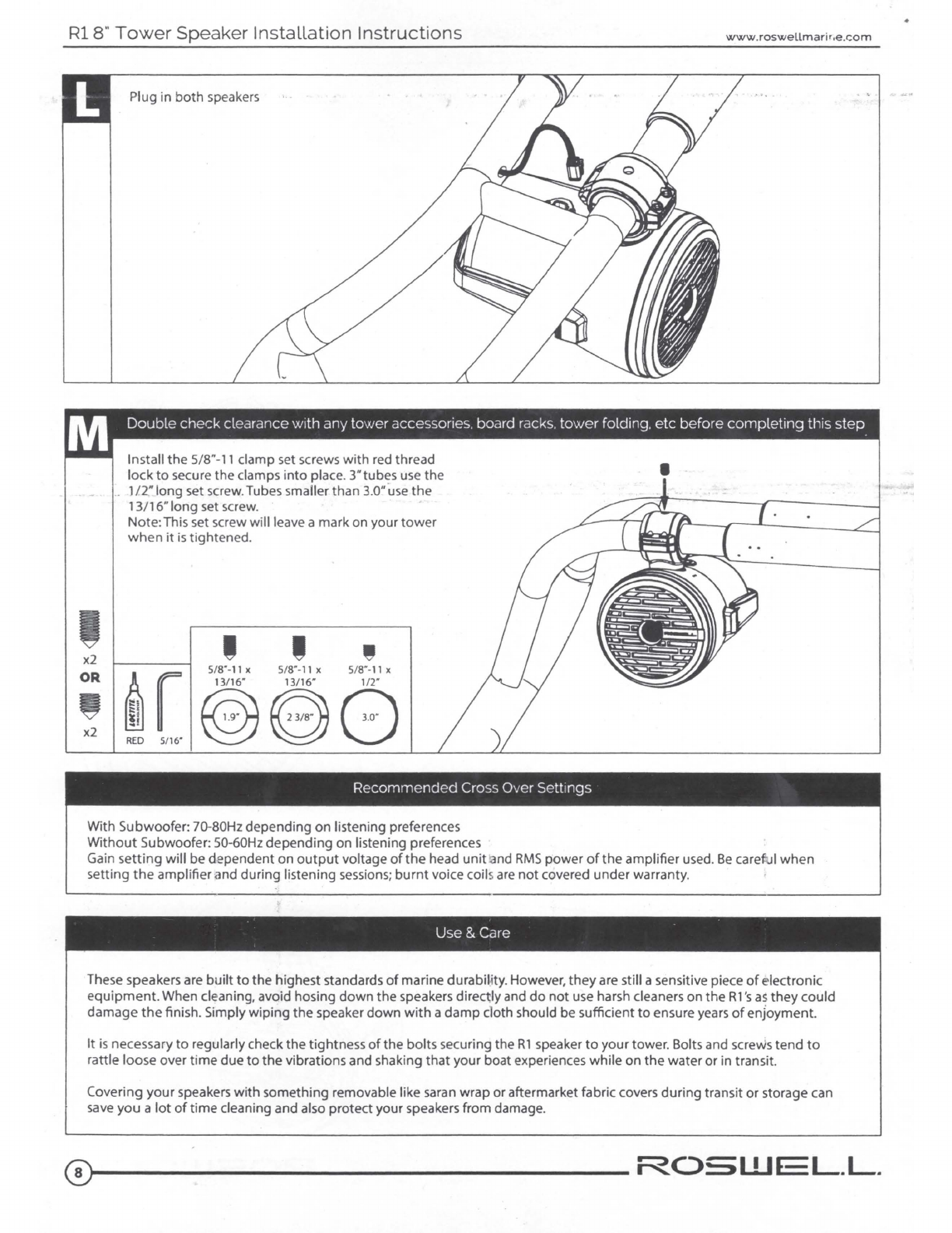
Tubing Size
•These speakers include three different inserts for
the
tl'bing
clamp:
3.00~
2.375"and 1.
90~
Ifyour
tower
requires aclamp insert
not
. /
provided
please contact Roswell at 1
(321
)-638-1331 for optional inserts.Alternative
sizes
available are: 2.85", 2.50" and 2.
25#.
WARNING
•These speakers are capable
of
easily producing sound pressure levels
(SPL)
in
excess
of
100
dB,
even in
an
open-air
environment
like a boat. Sound pressures at
or
above these levels can easily
cause
permanent hearing damage
or
loss.
Be
sure
to
use safe
listening practices and protect your ears.
3
.,__
__________________
ROSWf
L.L.