4
Wheel
Spotting Dish
2' 5"
APPROACH
PVC Conduit
Entrance for Air
& Hydraulic Hose
NOTE: Adjust Entrance
For Pedestal Mounting
Installation See Fig. 8a
4' 9" Swing Arm Lifts
5' 0" Moveable Pad Lifts
WORK BENCH (TYPICAL)
12'-0" Min. to
Nearest
Obstruction
or Per
Section 1c
5'-6" Min. to nearest obstruction
Foot traffic only on center cover
SL210i Series
Wheel
Spotting Dish
2' 5"
APPROACH
PVC Conduit
Entrance for Air
& Hydraulic Hose
NOTE: Adjust Entrance
For Pedestal Mounting
Installation See Fig. 8a
4' 9"
WORK BENCH (TYPICAL)
13'-0" Min. to
Nearest
Obstruction
or Per
Section 1c
5'-6" Min. to nearest obstruction
SL212i Series
PVC Inlet Into Containment Tube
Foot traffic only on center cover
PVC Inlet Into Containment Tube
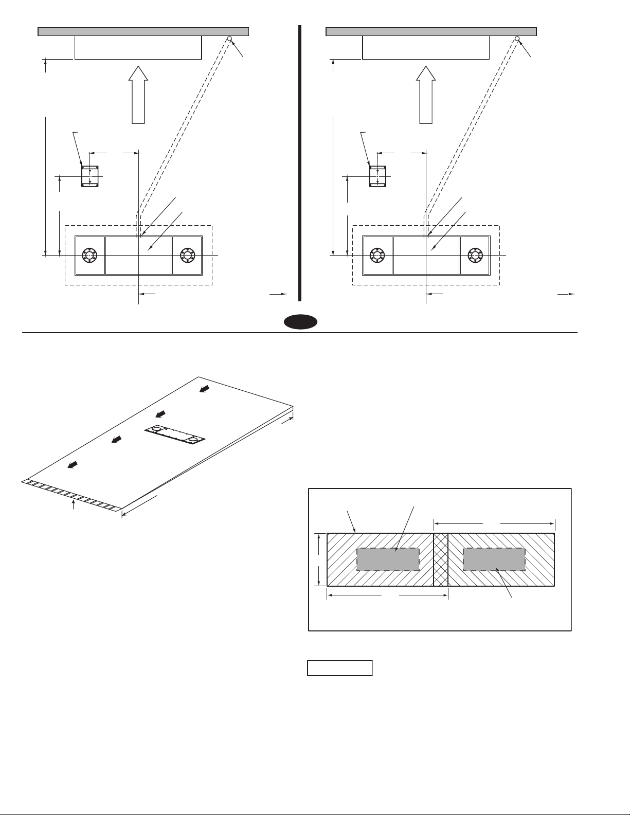
1. Lift Location:
A. Check architect’s layout if available. Lay out lift as shown in
Fig. 1. Recommended floor slope is 1/16" per foot.
B. SL210i: The 5' 6" centerline to side and 12' 0" centerline
to front and rear dimensions should be maintained to provide
adequate working space. The minimum overhead clearance
should be 85" plus height of highest vehicle to be raised. 24' 0"
length bay recommended. Other lengths may be used, provided
ample clearance is maintained at each end of lift.
SL212i: The 5' 6" centerline to side and 13' 0" centerline to front
and rear dimensions should be maintained to provide adequate
working space. The minimum overhead clearance should be
88" plus height of highest vehicle to be raised. 26' 0" length bay
recommended. Other lengths may be used, provided ample
clearance is maintained at each end of lift.
C. Base Unit Lifts: If you are planning to install roll-on/
wheel alignment runways, locate lift per instructions from
superstructure manufacturer. Use superstructure manufacturer's
instructions for fore and aft, side to side, and ceiling clearances.
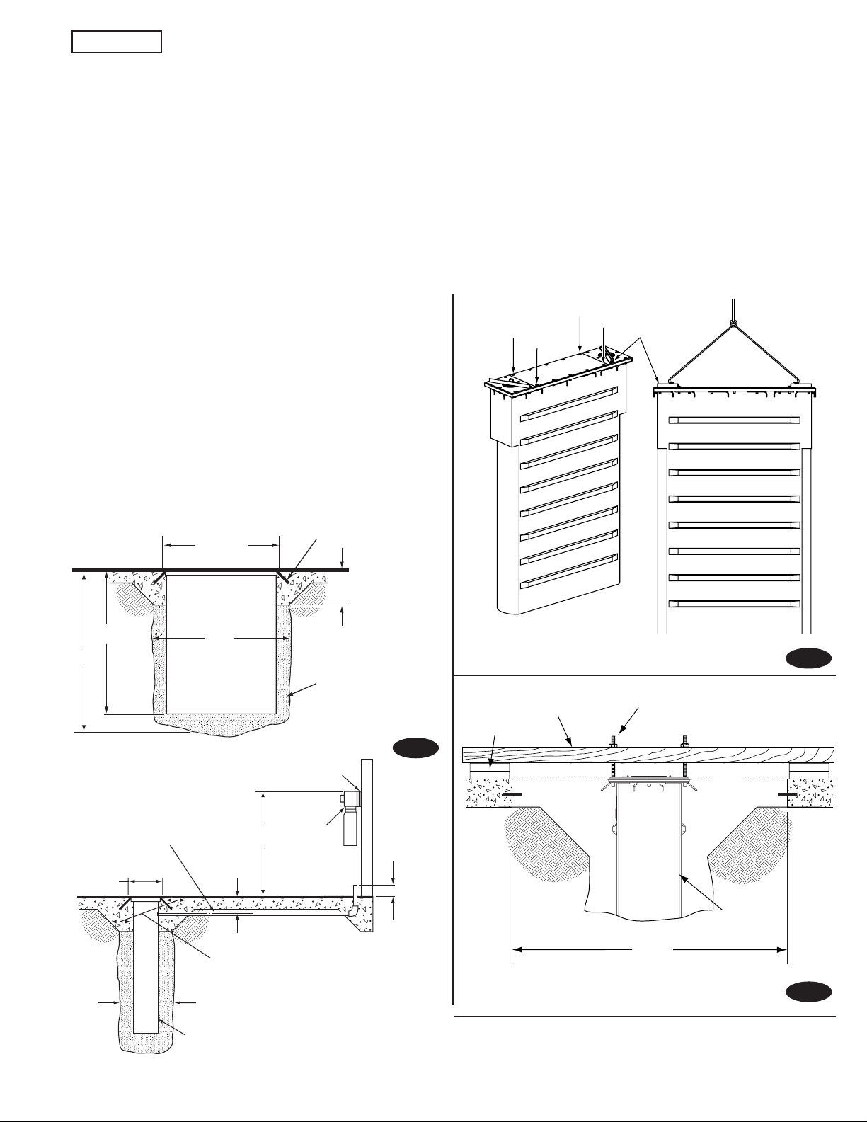
2. Excavation: Excavate hole to dimensions shown in Fig. 2.
Dig trench for 2" PVC pipe between lift and power unit location.
Trench should be dug 11" below finished floor grade. Air line and
hydraulic hose to be contained in this 2" PVC pipe.
3. Concrete Preparation:
A. Run 2" PVC from Control Area to Containment Tube. PVC will
enter the Containment Tube 9-1/2" below finished floor grade.
Hole is centered horizontally in Containment Tube, Fig. 1.
B. Box out a 5' x 10' area around where lift is to be located.
NOTE: For multiple lift installations, boxed out areas will
overlap. Dig continuous trench, see illustration below.
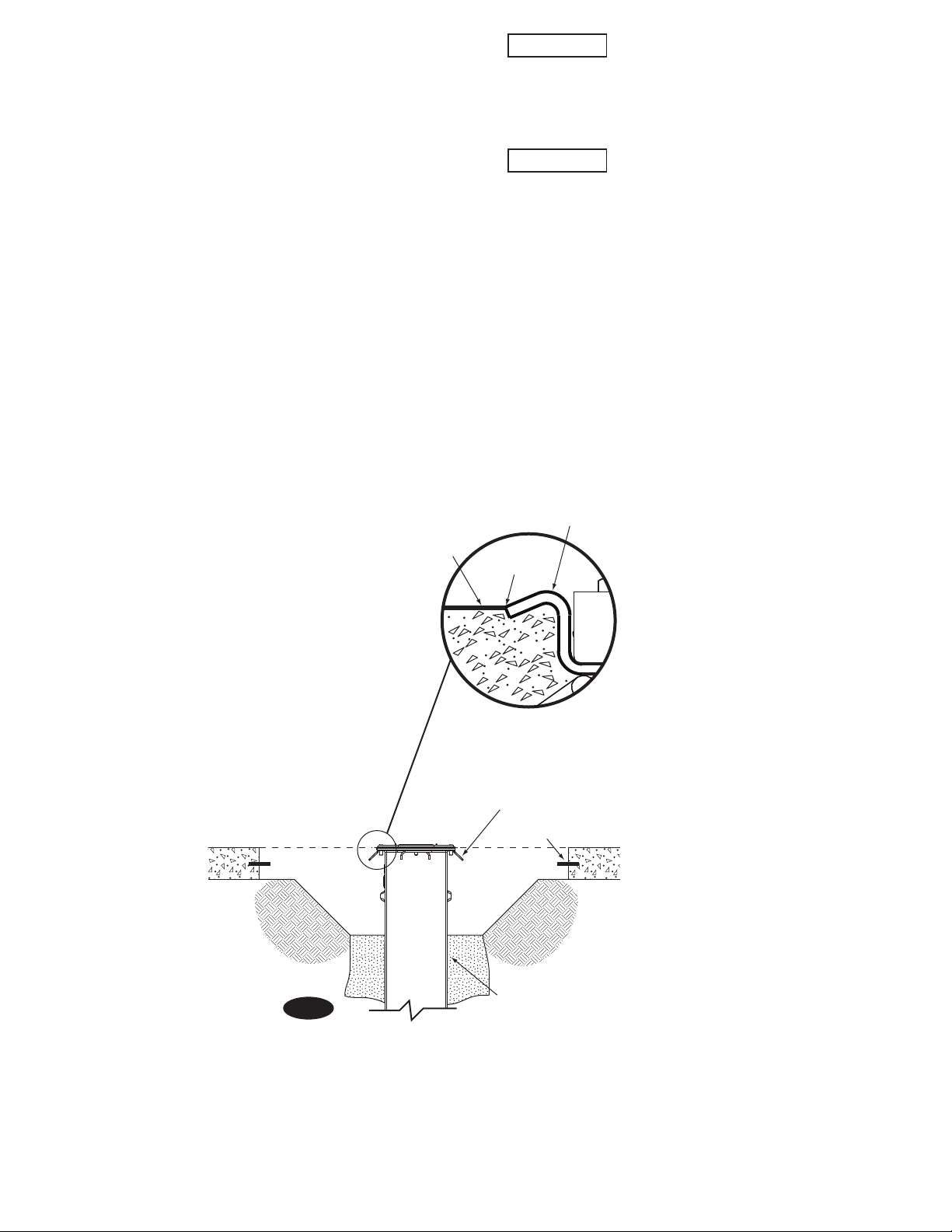
C. Pour concrete floor ensuring not to get concrete in boxed out
area.
NOTE: By using this installation method, the RAI can more
accurately set lift to proper grade relative to finished floor.
Reference Page 2.
Fig. 1
4. Lift Setting:
Check the containment tube for holes due to
shipping damage. Do not install a damaged containment tube.
Contact Rotary Lift Customer Service.
A. Chain hoist must have capacity of 2,500 lbs. with a clear
swing of 9' 0". Rig sling for unit, attaching to the shipping strap,
Fig. 3, and lower assembly into hole. Center lift and be sure lift
containment inlet is located as shown in Fig. 1.
Recommended Floor Slope 0-1/16" Per Ft.
Drainage Direction Drainage Direction
Drain
Continuous Trench
Lift Location
5'
Concrete Floor
10'
10'
Lift Location