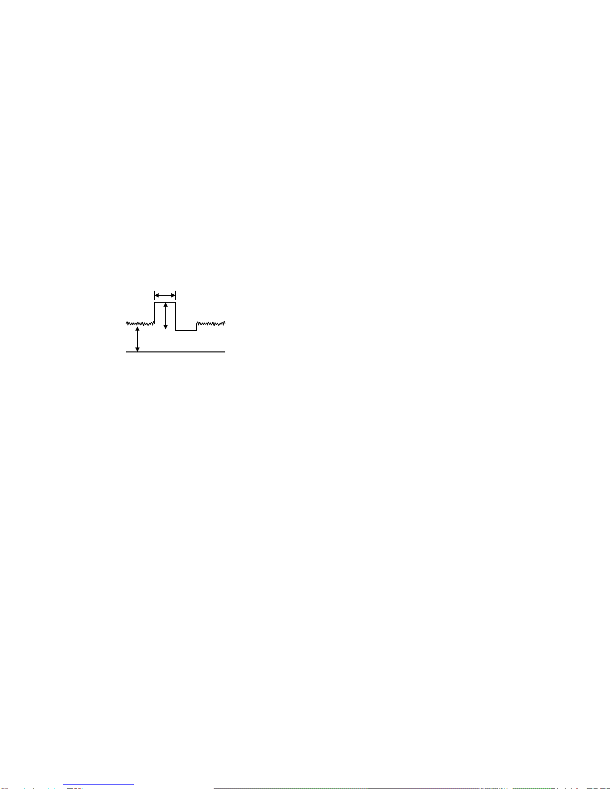
Rotel RDV-985 User manual

Technical
Manual
DVD PLAYER
RDV-985
Table of Contents
Specification......................................1
Information........................................2~17
Parts List...........................................37~47
Block Diagrams.................................18~22
PCB Assembly..................................34~36
Schematic Diagram ..........................23~33
SHINSEN-BLD. 4F 10-10 SHINSEN-CHO, SHIBUYA-KU,
TOKYO 150-0045, JAPAN
Serial. NO.
Beginning
®
Quality Uncompromised
Y-356A-0109/W
THE ROTEL CO., LTD.
Specifications
General
Readable Discs: DVD VIDEO, Audio CD, VIDE CD, SUPER VIDEO CD
Video Fomat: PAL or NTSC selectable
Video Output
VIDEO OUT (pin jack): 1.0 Vp-p (75 ohms)
S-VIDEO OUT (S jack):
Y Output: 1.0 Vp-p (75 ohms)
C Output: 286 mVp-p (75 ohms)
Horizontal Resolution: 500 Lines
Signal to Noise Ratio: 65 dB
Audio Output
ANALOG OUT (pin jack): 2.0 Vrms (10 kohms)
DIGITAL OUT (optical): - 21 to -15 dBm (peak)
Audio Characteristics
Frequency Response:
CD: (sampling frequency 44.1 kHz): 2 Hz to 20 kHz
DVD (sampling frequency 48 kHz): 2 Hz to 22 kHz
DVD (sampling frequency 96 kHz): 2 Hz to 44 kHz
Dynamic Range:
16 bit: More than 100 dB
20 bit: More than 108 dB
24 bit: More than 108 dB
Wow and Flutter: Unmeasurable (less than ±
Total Harmonics Distortion: Less than 0.002%
0.002%)
Physical
Power Requirements:
USA Version: AC 120V, 60 Hz
European Version: AC 230V, 50 Hz
Power Consumption: 23 W (POWER ON), 2 W (STANBY mode)
Weight: 4.7 kg (10.4 lbs)
Dimensions (W x H x D): 445 x 112 x 338 mm
171/2 x 47/16 x 135/16 inch

Appearance

(1) Auto adjustment method
(2) Confirmation of DVD RF level
(3) Confirmation of CD jitter level and RF level
If microprocessor (IC401, IC402, IC714, IC716) or servo board (LEA10047) is replaced, initialize
the DVD player in the following matter:
ref. separate sheet.
Adjustment and confirmation matter
1.The oscilloscope is connected between "1"(RFOP) of
CN104 and "2"(GND).
2.Reproduction of the test disc ( VT-502)
made by JVC.
3.It is confirmed that RF LEVEL is 350mVp-p 150mVp-p.
4.When there is disorder in the waveform road cuts etc,
test disk is exchanged and measured.
1. The CD jitter meter is connected between "11"(GND)
of CN104 and "12"(FLTOUT).
The RF level is observed at the same time.
2.The first test disk(CTS-1000) made of JVC is reproduced.
3.It is confirmed that RF LEVEL is 360 100mVp-p.
5. When there is disorder in the waveform road cuts
etc, test disk is exchanged and measured.
FRONT SIDE
12 ~ 1
RFOP
GNDGNDFLTOUT "1""2""11""12"
CN104
Main Adjustment
DVD SERVO CONTROL PWB
+
+

RDV-985 is adjusted from issue machine because of the FL display on the way.
Please go in the adjustment method before changes according to the following procedures.
Attention !!
Measurement
CN104 pin"1"
GND:CN104 pin"2"
Adjustment point
Refer to Fig.2
Mode
Reproduction
part
Disc
Measurement machine
Oscilloscope
VT-502
DVD Mechanism A'ssy
Stand Stand 200mm
RDV-985
Fig.1
CN101 of DVD Servo Control PWB
CN11 of
Connection PWB
Extension Cord
connections
Refer to Fig.1
Extension cord No.
QUQ110-3740AM
General tool : Hex-head wrench(2mm)
(4)Flap adjustment of the Pick-up guide shaft

Confirmation after adjustment.
Confirm to reproduce video CD and CD after
the DVD test disc is adjusted and to find abnormality.
(5) About keeping the disc
As for the DVD test disc, plane accuracy is demanded.Please note the keeping place on the disc.
1. Please do not put the disc directly on the work desk etc. after uses .
2.T o keep the planarity of the disc, politely handle ,and please put in a special case and keep
the disc v ertically after uses .
Please k eep keeping the disc in a cool place where direct sunshine and the air-conditioning
wind do not dr ive.
3.When the disc cur ves,an accurate adjustment cannot be done.
Please exchange for a new test disc and adjust optics.
4 Other discs might not be ab le to be reproduced when adjusting on a curved disc.
A
A
B
Fig.2
Point of adjustment
* Please execute the static electricity protection measures before starting the
adjustment.
* When the following parts are exchanged,optical adjustment "Adjust the flap of the disc motor"
is necessary.
1.The disc motor w as exchanged.
2.The laser pic k up was exchanged.
3.The tr averse motor unit was exchanged.
Note
Additionally , please adjust the flap of the disc motor when the picture quality deterioration is
seen .The basic adjustment though, is unnecessar y for part exchange in the traverse.
An optical adjustment in the laser pick up cannot be done.
Please adjust the flap of the disc motor after e xchanging the laser pick up.
* When the traverse unit is exchanged, the adjustment is basically unnecessary.

Check points for each error
(1) Spindle start error
*Defective spindle motor
Are there 10ohms resistance between each pin of CN101 "29~31"?
(The power supply is turned off and measured.)
*Hall element: Is sine wave output between CN101 "23" and "24", between "25" and "26",
and between "27" and "28" during rotation?
In either case, replace the mechanical unit.
*Defective spindle driver (IC251)
Is a driving wave output from CN101 "29~31" ?
Is IC251 "9" at "H" level (START)?
Servo IC --- Is control signal sent to the motor driver ?
IC201 "95" : Duty is 50% during stop, but varies during rotation (greatly varies at start).
--- If not sent, pattern or servo IC (IC201) is defective.
R259 : approx 2.5V during stop, but varies during rotation (greatly varies at start).
--- of not sent, pattern or servo IC (IC201) is defective.
Is FG input to servo IC ?
Observe FG wave from IC201 "89". --- If not output, pattern, IC251 or IC201 is defective.
During
rotation
(2) Disc Detection, Distinction error (no disc, no REFNV)
* Laser is defective.
* Front End Processor is defective (IC101).
* APC circuit is defective. --- Q101.
* Pattern is defective. --- Lines for CN101 "15" and "17".
Lines for between IC201 "2" and IC101 "2"(LDONA),
between IC201 "3" and IC101 "1" (LDONB).
* Servo IC is defective (IC201).
* Is signal sent to IC201(servo)"71" AS2 ?
* IC101 --- For signal from IC101 to IC301, is signal output from IC101 "88" (RFAS1) and
IC101 "69" REENV ?

50msec
Approx.
500mV GND
2.5V
(3) Traverse movement NG
* For automatic adjustment, traverse movement occurs only when the position is changed to retry
judging the disc type after the 1st judgment resulted in an error. Therefore, traverse movement
rarely occurs because, in most cases, disc judgment at the current position (1st time judgment)
is executed successfully. (Of course, NG rarely occurs in this step.)
Note: 1st time judgment of disc type resulted in NG. --- The re-judgment of disc type may not be
successful. Therefore, after removing the cause of traverse movement, re-execute automatic
adjustment and confirm that no problem exists.
* Check point
a)During stop
Whether 50% duty pulse is output to R273
Whether between R274 and C271 is at approx. 2.5VDC
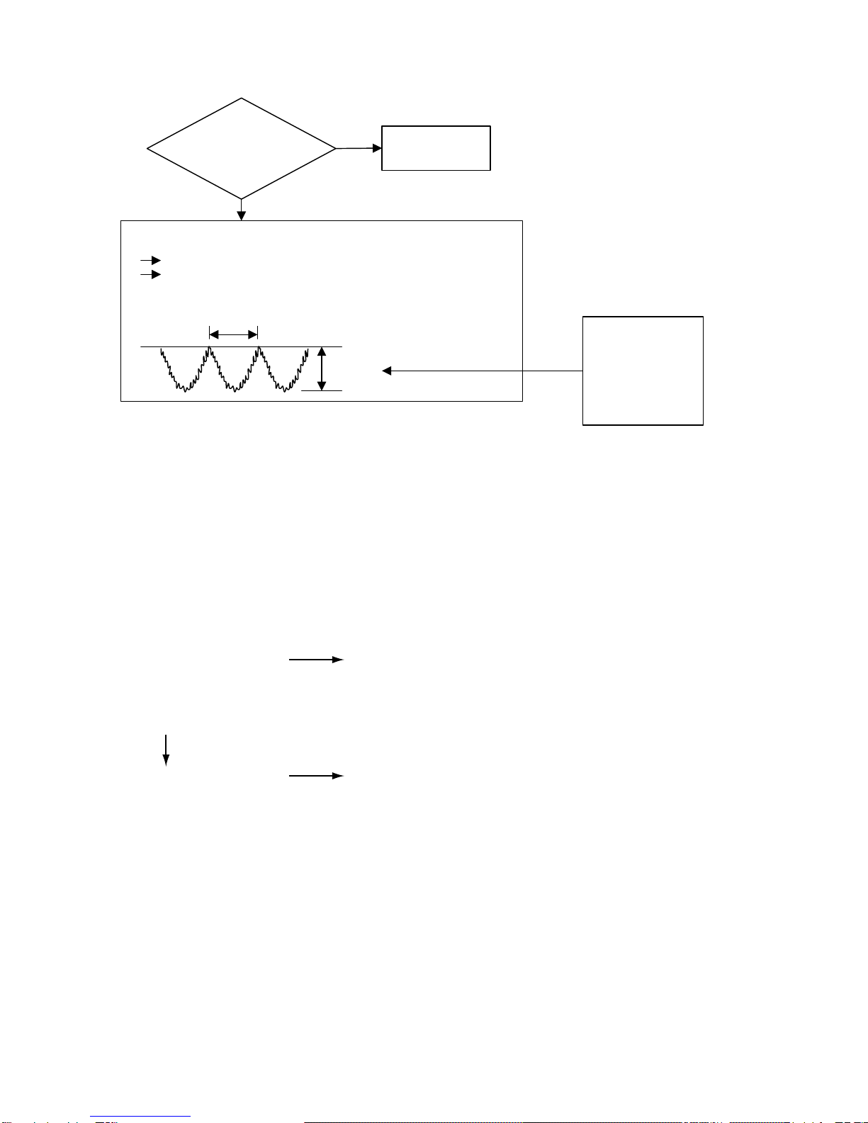
Offset voltage between CN101 "34" and "35" (scores mV if exists)
b)When tray is opened or closed
Check by oscilloscope whether a rectangular wave signal is output from CN101 "34" or "35".
If checking a) or b) resulted in NG, IC201 maybe defective.
(4) Focus ON NG
* Is FE output ? --- Pattern, IC101
* Is FCDRV signal sent ? (R286) --- Pattern, IC301
* Is driving voltage sent ?
CN101 "20", "21" --- If NG, pattern, driver, mechanical unit (with the power turned off, measure the
resistance between CN101 "20" and "21").
* Does CN101 "7"(SRF1) become "H" and is the focus drawing in done?
--- Mechanical unit (laser power too low), IC101(defective gain)
--- Moreover, It is thought that abnormality is found in the disk.
* Mechanical unit is defective.
(5) Tracking ON NG
* When the tracking loop cannot be drawn in, IC201 "39" (/TRON) does not become "L".
* Mechanical unit is defective.
Because the under mentioned adjustment value is abnormal, it is not possible to draw in normally.
* Periphery of driver (IC271)
Constant or IC it self is def ective.
(When passing without becoming abnor mal while adjusting the following.)
* Servo IC (IC201)
When improper ly adjusted due to defective IC.
[F ocus position rough adjustment]
[Phase diff erence cancellation rough adjustment]
[T racking balance adjustment]

(6) Spindle CLV NG
* When the spindle cannot be shifted to CLV Servo, does not become "H" between IC301 "69"
and IC201"37".
* IC201 Is signal output from CN103 "1" (RFOP)?
* IC201 Is signal output from CN103 "11" (DSLIP)?
* IC201 Is signal output from CN103 "6" to "9" (binary-coded clock and data)?
* IC201 Is "39" (/TRON) at "L" level ?
* IC301 "74" to "76" --- Is signal output to IC201 "24", "25", "28" (In case of only CD).
(Serial communication of rotation information)
* Spindle motor driver is defective.
Even when one of the three phases is defective, item (1) may be passed.
--- Check the second item in (1) above.
* C260 to C263 Defective soldering
If noise eliminating capacitors are not properly soldered, noise may ride on the waveform.
* Besides, the undermentioned cause is thought though specific of the cause is difficult because various
factors are thought.
Mechanism is defective.(jitter)
IC101, IC201.
* Besides, the undermentioned cause is thought though specific of the cause is difficult because various
factors are thought.
Mechanism is defective. (jitter)
IC201, IC301, IC401.
The disc is dirty or the wound has adhered.
(7) Address read NG
(8) Between layers jump NG (double-layer disc only)
* When the focus flight is generated when jumps between layers.
Because all adjustments for L1 layer must be successful, this error may rarely be due to a
circuit defect.
* Crosstalk might occur from tracking to focus system. (See (11) ) --- Replace the mechanical unit.
* Driver surroundings.
* Defect of constant and IC.
* For double-layer discs, after checking CLV on layer L1, jumps to layer L0 after mode changes to FG.
Then tracking is turned off, and adjustments are executed from the focus position coarse adjustment
in order.
* When the jump between layers is done on the single-layer disk, the disk distinction error is thought.
--- The laser power is low (RF level is confirmed by CN102 "1" (RFOP)).
--- AS1, AS2, REFNV Is the signal sent to between IC101 and IC201 ?

Long-distance seek
Feed
Tracking
Hold (DC) during feed
Acceleration pulse at start;
deceleration pulse at stop
(each one)
(In the direction of search,
opposite to this figure)
Kick pulse (fine seek) is
inserted after long-
distance seek.
(Not one)
Kick pulse
Approx.
2.5V
(9) Neither picture nor sound is output
* Cannot search
a) Can the feed system be driven?
Chec k the waveform of TRSDRV signal (R273). --- Waveform between R274 and C271.
Search results in a change of duty
(three v alues with 2.5V at the center)
(The figure is e xaggerated.)
Chec k the waveform of CN101 "1" and "2". --- After the driver (IC271)
b) Is kick available?
Chec k the TRDRV signal waveform from R289.
Chec k the waveform of CN101 "22" and "23" --- After the driver (IC271)
Although diff ers in amplitude and DC offset, the waveform is similar to that of R289
For short-distance search, the waveform
becomes roundish, not trapezoidal, and
voltage is low.

(10) Picture is distorted or abnormal sound occurs at intervals of several seconds.
Does JITOUT
change periodically?
(2V or more in peak
value, except
during kick)
NO
YES
Some system other
than servo may be
defective.
Feed system is defective (drive gain is defective: too large).
Check the waveform according to a) in (9).
Play back a simple disc with no angle change.
OK when the following waveform appears at intervals
of several seconds.
5~10Sec.
1~1.2V
If this voltage is too
high (2V or more, for
example), feed motor
may be defective, or
the mechanical unit
has seized.
(11) Others (unusual events experienced to date)
(13) Others
* Problem occurs with double-layer discs although no problem occurs with single-layer DVD.
(Error occurs, or search becomes unstable and takes longer.)
Crosstalk might occur from tracking to focus system.
--- When FE was observed during search (skip, etc.), it was found that a wave resembling TE
with an amplitude of 200mVp-p was riding on FE.
--- Mechanical unit was replaced.
* Error frequently occurred in the outer part of discs although no error occurred in the inner part.
--- Mechanical unit was replaced because tilt seemed to be defective.
V-CD : Frequent occurrence of error in inside and outer.
(Even the disk without the wound : when generated.)
Waveform observation
--- Is the oscillation frequency of about 700~900Hz output?
(Borrow a pertinent disk for the complaint for the combination with the disk.)
--- Exchanges mechanism for the mechanism resonance.
(12) CD During normal playback operation
a) Is TOC reading normal?
Displays total time
for CD-DA.
Shifts to double-speed
mode for V-CD.
b)Playback possible?
Please refer to "Servo Volume" flow.
*--:-- is displayed during FL serch.
According to [*Cannot serch ] for DVD(9), check the feed
and tracking systems.
*No sound is output although the time is displayed.(CA-DA)
*DAC, etc, other than servo.
*The passage of time is not stable, or picture is abnormal.(V-CD)
*The wound of the disc and dirt are confirmed.
NO
NO
YES

Precautions for Service
Handling of Traverse Unit and Laser Pickup
1. Do not touch any peripheral element of the pickup or the actuator.
2. The traverse unit and the pickup are precision devices and therefore must not be subjected to
strong shock.
3. Do not use a tester to examine the laser diode. (The diode can easily be destroyed by the
internal power supply of the tester.)
4. To replace the traverse unit, pull out the metal short pin for protection from charging.
5. When replacing the pickup, after mounting a new pickup, remove the solder on the short land
which is provided at the center of the flexible wire to open the circuit.
6. Half-fixed resistors for laser power adjustment are adjusted in pairs at shipment to match the
characteristics of the optical block.
Do not change the setting of these half-fixed resistors for laser power adjustment.
Destruction of Traverse Unit and Laser Pickup by Static Electricity
Laser diodes are easily destroyed by static electricity charged on clothing
or the human body. Before repairing peripheral elements of the traverse
unit or pickup, be sure to take the following electrostatic protection:
1. Wear an antistatic wrist wrap.
2. With a conductive sheet or a steel plate on the workbench on which
the traverse unit or the pick up is to be repaired, ground the sheet
or the plate.
3. After removing the flexible wire from the connector (CN101),
short-circuit the flexible wire by the metal clip.
4. Short-circuit the laser diode by soldering the land which is provided
at the center of the flexible wire for the pickup.
After completing the repair, remove the solder
to open the circuit.
Short-circuit

Is the AC
wave detected on
the anode side of
D953?
Does the
oscillation wave
come out to
IC901"3"?
P.STAND-BY
indicating lamp
lights up?
Connect to outlet.
Press POWER switch.
STANDBY
indicating lamp
goes out?
A
Check S867
(power switch)
and the line
to IC714.
F901
fuse is blown
Does FL
light up?
Correct
voltage applied at each
lead
of FL?
Correct voltage
applied to IC831
(FL driver)?
Replace
F901.
Voltage of
IC953"1" at
approx.5.6V?
Oscillating
wave output from
IC831"20"?
Voltage
of IC831"13"
(P.ON RESET)
at +5V?
Check
IC831,R843
and C833.
B
Is connection
between IC831"13"
and IC714"76" OK?
Repair the wiring.
Voltage
of CN831"19"
at +5V?
Replace IC831.
Voltage
of IC953"3"
at 5 V? Replace
IC953.
Continuity
OK between IC953"3"
and IC714"16",
"62" and "99"?
Is IC953
hot?
to
Micro-
computer
Volume.
to Power Supply
Volume.
To Microcomputer
Volume. Repair the
wiring.
NO YES
NO
NO
YES
YES
NO
YES
YES
YES
YES
NO
NO
NO
NO
YES
OK
NG
YES
NO
NO
YES
YES
NO
YES
NO
YES
NO
YES
NO
YES
YES
NONO
YES
NO
Power-on
processing is OK.
To Microcomputer Volume.
Is connection
of IC831"14"-"16" and
IC714"2" to "4" OK?
To Microcomputer
Volume.
to Power Supply
Volume.
to
Micro-
computer
Volume.
Return to A
and recheck.
Replace
D901.
Return to A
and recheck.
Replace
IC901.
Return to A
and recheck.
NO
Replace
D953.
Return to A
and recheck.
Return to A
and recheck.
Return to A
and recheck.
Return to A
and recheck.
Return to B
and recheck.
Return to B
and recheck
Return to B
and recheck.
Does
the lamp
goes out when
POWER switch of
remote control
box is turned
ON?
Repair the
wiring.
Return to A
and recheck.
Repair the
wiring.
YES
NO
YES
Troubleshooting
1.Power-on processing
Does the
DC voltage(input
AC 1.4V) come out to
D901 output side
Is energizing
of "cathode of D953"
and "pin1 of IC953"
normal?
Connecting wires
to the soldered
part of the pins of
T902(transformer)
and anode of T902
is examined.

2. Power Supply Volume
With all the wiring removed, check unit power board.
(1) Remove all flat wires and wire assemblies which are connected to CN801, CN805, CN806.
(2) Short -circuit CN805"4" (POWER ON:B168) and "5" (B5V:B167). (Set each regulator to ON.)
(3)
(4) Connect to the outlet and check the voltage at each part.
(For the voltage specification, see the wiring diagram.)
Then restore the connection of CN801, CN805, CN806 and check voltage.
(1) Remove the wire short -circuiting CN805"4" and "5".
(2) Remove the load resistance.
(3) Restore the connection of CN801, CN805, CN806.
(4) Connect to the outlet.
(5) Turn the POWER switch on and check the voltage at each part.
If voltage abnormally drops when CN801, CN805, CN806 are connected (load is connected) though the voltage
was at the normal level when CN801, CN805, CN806 were disconnected(load is connected), or if the protective
element (fuse, etc.) is opened, the load which is supplied power may be defective or the wiring may be
short-circuited.
The load resistance is connected between CN805"5"(B5V:B167) and "8,9"(D.GND:B164).
* If the load resistance is not connected, the voltage is not output to "B167".
3. Open/Close Operation
Press OPEN/CLOSE key
Does the tray
smoothly open?
Voltage
of IC401"52"
at 0V?
of
the remote control
box functions
normally?
Any
voltage applied
between CN102"4"
and "5"?
Check the
connection
between CN102
and mechanical
unit. Check the
mechanical unit.
Check IC251 and
the periphery.
To Microcomputer
Volume.
Check S835 (OPEN/
CLOSE) and the
wiring to IC714.
YES
NO
Press in by hand
when fully opened.
Voltage
between CN102"4"
and "5" at 0V when
tray ends
retreating?
Voltage of
CN102"3" at 0V when
tray closing
ends?
OPEN/CLOSE
operation is OK.
Check the connection between
CN102 and mechanical unit.
Check the mechanical unit.
Voltage of
CN102"1" at 0V when
tray opening operation
ends?
Ejected
Voltage of
IC401"52" at 0V when
tray opening operation
ends?
Replace IC401.
Check the
connection of
CN102"3" and
IC401"51".
Voltage of
IC401"51" at 0V when
tray closing
ends?
NO
NO
NO
YES
YES
YES
YES
YES
NO
NO
NO
NO
YES
YES
YESYES
NO
Does the tray
retreat? Check the connection between
CN102 and mechanical unit.
Check the mechanical unit.
Check the
connection
of CN102"1"
and
IC401"52"
Replace IC401

4. Microcomputer Volume
Processing of Each Microcomputer
*IC714 System microcomputer (sub-microcomputer)
After powering on, this microcomputer is continuously activated to control keys and remote control
signals.
According to key operations or remote control signals, it controls (turns on/off) the power for
LSIs including IC401 (main microcomputer) and the audio/video output circuit.
It also controls the resetting of the main microcomputer, FL driver IC (IC831) for FL display, and
various LED displays.
*IC401 Main microcomputer
This microcomputer controls a group of LSIs of servo and signal processing sections according to
commands from the system microcomputer.
After receiving time information from the signal processing section, it transmits the information
together with the status to the system microcomputer.
It controls the resetting of the LSIs of the servo and signal processing sections.
It has IC402 (16Mbit ROM) as an external ROM.
Normal Starting Conditions
* IC714 System microcomputer
(1) +5V must be applied to "16" and "62".
(2) Oscillators of "13" and "15" must be oscillating correctly.
(3) Input to "12" (RESET) must be at +5V (reset cancel).
If above (1) to (3) are not satisfied when the P.STANDBY indicating lamp does not light at
power-on, IC714 may be defective.
* IC401 Main microcomputer
(1) +5V must be applied to "17","22","34","54","66"
(2) Clock signal (13.5MHz) must be input to "23" from IC301 (ODC LSI).
(3) Input to "82" (RST) must be at +5V (reset cancel).
(4) Communication line with IC714 ("57","58,"67"~"69") and that with IC402 (external ROM)
("13"~"16","26"~"33","35"~"42","44","93"~"100") must work normally.
If above (1) to (3) are not satisfied when the P.STANDBY indicating lamp goes out but FL does not
light when the POWER switch is turned on, IC401, IC714 or IC402 may be defective.

5. Audio Volume
Power
supplied correctly
to each IC?
to Power Supply
Volume
YES
NO
OK
*
Is sound
signal output
from J702 (pin
jack)?
Is sound
output from
headphone?
Is sound
output from
headphone?
Check Q711,
Q712 and J702
(soldered part).
Voltage of
Q708 collector at
-12V?
Is
digital signal
output from
IC702"7"?
NO Check IC702
and PLL.
YES
Is
digital signal output
from IC701"20"?
NO Replace
IC701.
Is digital
signal output from
IC702"10", "13", "16"
and "19"?
Replace
IC702.
Check IC703, IC704
and their periphery.
When fs=44.1kHz
When fs=48kHz
When fs=96kHz
0.6V
0.9V
2.6V
* PLL normal lock voltage
Between TP701 and TP702.
* Changing over the cutoff frequency of analog LPF
When fs=44.1kHz or 48kHz,
Microcomputer port FS2 is at the "L" level,
and Q703 and Q704 are turned ON.
When fs=96kHz,
Microcomputer port FS2 is at the "H" level,
and Q703 and Q704 are turned OFF.
Approx
. 5V
YES
YES
YES
YES
NO NONO
NO
YES
NO
YES
CN704 is
checked
IC850
Q851,Q852
is checked
The position of
the screw
fastening the
front panel is
confirmed.
This screw : because
there is working
of the ground.
IC714 is
checked
IC702 are supplied
power from IC718.
Check I/O voltage of IC718.

Is video
signal output from
J603 composite
terminal?
Is video
signal output from
J602 S terminal?
6. Video Volume
YES
NO
Is clock
signal input to
IC551"9"?
*Service tips
(1) The disc playback screen is in the normal condition but graphics in the "ON SCREEN"
mode are abnormal => Replace IC553.
(2) Only 1/4 compressed playback screen of DVD or video-CD is abnormal => Replace IC552.
YES
YES
YES
YES
NO NO
NO
NO
NO
YES
Power
supplied correctly
to each IC?
to Power Supply
Volume
OK
Is signal
output from CN601"4" ?
* +5V power for video section is
supplied from IC654.
Check I/O voltage of IC654.
Is digital
signal output from
IC551"1" to"8", "10" and
"11"?
Check
IC551.
Check
IC501.
Check
IC501.
Check the insertion of
IC621,IC622,L604
L603,CN601
Check L603
L604,IC611
IC101
FEP
IC301
ODC
DISC IC702
DAC
IC501
AV DEC.
VIDEO
CIRCUIT
LPF AUDIO
VIDEO
Signal flow of DISC media

Press
"OPEN/CLOSE"
key
to OPEN/CLOSE
Operation Section
Is the opening
operation of
TRAY normal?
After "FL" displays
"Close", is "Reading"
displayed?
Does the DISC
rotate ?
Does pick-up
lens move up
and down?
Does the
displayed in FL
is "NO DISC"?
Is drawing in
FOCUS normal ?
(It is NG when
tick tack retrying.)
FE OFF ON
Is drawing in
TRACKING normal ?
Does IC201"39"
(/TRON) become "L" ?
TE
OFF ON
(14)Spindle CLV NG
(1)Spindle start error
Does CN101"4"
(SWTRV) become 0V ?
(3) Traverse
moving NG
(2) Disc detection,
Distinction error
(4) Focus ON NG
(8) Tracking ON NG
Is the shift to
spindle CLV OK ?
Does IC201"37"
(PLLOK) become "H" ?
7.Servo volume
Is the jump between
layers OK?
FE
LO LI
(16) Jump between
layers NG
Was information on
the disk obtained?
(In case of NG, disc
eject at tray open.)
(15) Address
read NG
Can you reproduce ? (9) Checkpoint
according to error
OK !
Y
Y
to A
N
N
N
N
N
N
N
N
N
Y
Y
Y
Y
Y
Y
Y
from A *only two layer
disc (DVD)
Y
Y
Y
N
N
N

LASER
PICK-UP
SPINDLE
MOTOR
FEED
MOTOR
LOADING
MOTOR
FEP
(Front End Processor)
IC101
AN8706FHQ
SPINDLE DRIVER
IC251
AN8485SB
4CH DRIVER
IC271
BA5983FM
CRYSTAL
X401
13.5MHz
ODC
(Optical Disc Controller)
IC301
MN103005ANZG
ADSC
(Advanced Digital
Servo Controller)
IC201
MN67705EA
OSC
X371
33.86MHz
IC371,IC372
TC7SH04FU
UNIT CPU
IC401
MN102LP25G
16M ROM
IC402
M27C1602CZ
IC374
TC7WH74FU-X VIDEO ENCODER
IC554
MC44724AVFU
+2.5 REG.
IC555
MC33269D
2M FRAM
IC552
UPD42280GU-30
(MN4777AS-XE)
GRAPHIC CONTROLLER
IC551
JCE8011
8M ROM
IC553
JCE8038-X
AV DECODER
IC501
ZIVA3-PA1
16M SDRAM
IC504
D4516161AG5-A10
(KM41651020CTG10)
(MN45V17160BT-10)
16M SDRAM
IC505
D4516161AG5-A10
(KM41651020CTG10)
(MN45V17160BT-10)
OPEN/
CLOSE SW.
REST SW.
OSC.
27MHZ
IC502
NAXO265-001X
IC507
TC7WH74FU
DVD MECHANISM
ASSEMBLY
ELM-V002
LD
PHOTO DETECTORS
ACTT+/-
ACTF+/-
TRVSW
TRAY IN / TRAY OUT
47~50
2~7
13, 28
20, 21
22, 26,28
25, 27
11, 12
13, 14
11
15~18
12,13 35, 3835, 38
59, 60
16~23 36
10, 11
163,172,173
8~11
2~4,6
95~100
15,27
1~ 8
178
159
15
5
1
3
13
9 25
FWD 0~7
FRD 0~7
CA 0~19
CO 0~7
3, 46, 7
12, 14
14, 99
39~46
51, 52
71, 76
118
2
91, 93
111
19,18
70,72
9,10
23
82
7
9, 20
9, 104,105
23, 26
68
16
108
45
99
27
CLK169
43
1
28
9
ERROR
SIGNALS
CONTROL
STATES
CPSCK
SDOUT
FG
ST/SP
FC
FEED +/-
M +/-
CONTROL
SIGNALS
TOPEN
TCLOSE
WAITDEC
WAITODC
STREAM DATAS . CD DA DATAS
LSI RST
23
1
CLK135
CLK338
CPU DATAS
CPU DATAS
CPU DATAS
CSDEC
WAIT
HSYNC
VSYNC
VD 0~7
DA DATA1
DA LRCK
DA BCK
C OUT
Y OUT
Pb OUT
Pr OUT
V5V
VREF
BLANK
FROM
CN601
OF
LVA10054-A2
(VIDEO &
JACK)
TO
CN701
OF
LVA10054-A1
(CPU)
D5V
D3.3V
M9V
DIGITAL 5V
DIGITAL 3.3V
MOTOR DRIVE 9V
POWER ON
FROM CN805
OF
LVA10053-A1
(Power Supply)
POWER ON
CN101
CN102
LVA10047
Block diagrams (DVD SERVO CONTROL Section)
AND GATE
OR GATE
IC311,IC312
TC7SH08FU
TC7SH32FU
WAIT
IC321,IC322
TC7WH74FU
TC74VHC00FT
CN503
CN502
CN501
6
4
8
10
6
5
2
8
1
11
15
19
21
10
31
32
3
7
8
1
33
~ ~

LINE FILTER
T901
QQR0894-001
AC-DC
D901
S1WB/A/60-4101
SWITCHING
REGURATOR
IC901
STR-F6652
AC-DC
D904
C914
AC-DC
D908
D910
TRANFORMER
T902
QQS0028-001
FEED BACK
PC901
PC123F
Q961
2SC1740S/
RS/
MODE SW.
PC902
PC123F
AC-DC
D956
C982,C984
L957
AC-DC
D957
C987,C989
L959
ON/OFF
Q955,Q956
DTA114YS,
TDC144ESA
ON/OFF
Q959,Q960
MUTE DETECTION
D972,D973
Q966
C965,C966
+12V REG.
Q953,Q954
2SB1565/EF/
2SC1740S/RS/
D961,D963
-12V REG.
Q957,Q958,
Q964
DTC114YS,
DTA114ESA
2SC2394/EF/
D962
AC-DC
D954
C979,C997
L955
AC-DC
D953
C965,C966
L952
AC-DC
D952
C963,C964
L961
AC-DC
D951
C960
-30V REG.
Q962
2SA933S/RS/
D950
+5V REG.
IC953
LM2940CT-5.0
+5V REG.
IC951
PQ05RF2
+3.3V REG.
Q964,Q965
2SB1565/EF/
2SC1740S/
RS/
FL ON/OFF
Q951,Q952
2SC2060/QR/,
DTA144ESA-T F1
F2
-VDSP
B5V
D5V
FROM FW831 OF
LVA10053-A2
(DISPLAY)
B5V
D5V
P.ON
D3.3V
M9V
FROM CN501 OF
LVA10047
(DVD SERVO
CONTROL 1)
V+12V
+12V
-12V
P.MUTE
FROM FW702 OF
LVA10054-A1
(CPU)
AC IN
LVA10053-A1
Block diagrams (DC REGURATOR Section)
1
2
3
4
5
-20V
-24V
-26.3V
4.9V
5.0V
7
6
8
5
2
1
3
5
6
4
2
1
13
D960
116
15
14
11
10
9
7
5
4
1
CN806
CN805
CN801

J601
LVA10054-A2
V5V
Pr 1
2
CN601
3
3
3
1
1
Pb
Y
4MHz LPF
L601
QQR0712-001
4MHz LPF
L602
QQR0712-001
6MHz LPF
L603
QQR0713-001
3.58MHz BPF
L604
QQR0714-001
C
IC601
Pr,Pb AMP
NJM2267D
Pr
8 8
1 5
2
5
4Pb
Y
41
58
COMPONENT
VIDEO OUT
J602
COMPOSITE
VIDEO OUT
J602
S-VIDEO
OUT
IC622
C AMP
NJM2268D
(2/2)
IC622
COMPOSITE AMP
NJM2268D
(1/2)
Q672
TO CN702
LVA10047
(DVD SERVO
CONTROL 2)
VIDEO SIGNAL IN
LVA10054-A1
IC702
LPF
MN35503-X
TO CN502 OF
LVA10047
(DVD SERVO
CONTROL 1)
Bloc k dia grams (VIDEO OUT & A UDIO OUT)
AUDIO DATA IN
TO CN502 OF
LVA10047
(DVD SERVO
CONTROL 1)
1
4
IC703
LPF
NJM4580L
IC704
LPF
NJM4580L
DIN OUT1D
OUT2D
13 2
16 2
2
15
7
7
1
J702
J706 OPTICAL
DIGTAL OUT
GP1F32T
Lch
Rch
AUDIO OUT
15
10
8
4
6
IC621
Y AMP
NJM2268D
8
1
5
4
3
4
Y
C
CN701
IEC958
Other manuals for RDV-985
4
Table of contents
Other Rotel DVD Player manuals

Rotel
Rotel RDV-1080 User manual

Rotel
Rotel RDV-995 User manual

Rotel
Rotel RDV-1050 User manual

Rotel
Rotel RDV-1080 User manual

Rotel
Rotel RDV-1062 User manual

Rotel
Rotel RDV-985 User manual

Rotel
Rotel RDV-03 User manual

Rotel
Rotel RDV-1060 User manual

Rotel
Rotel RDV-1093 User manual

Rotel
Rotel RDV-1060 User manual

Rotel
Rotel RDV-985 User manual

Rotel
Rotel RDV-1062 User manual

Rotel
Rotel RDV-1040 User manual

Rotel
Rotel RDV-1092 User manual

Rotel
Rotel RDV-1045 User manual

Rotel
Rotel RDV-1050 User manual

Rotel
Rotel RDV-1060 User manual

Rotel
Rotel RDV-1093 User manual

Rotel
Rotel RDV-1050 User manual

Rotel
Rotel RDV-985 User manual