Roto-Mix 200 User manual

Mixers by
ROTO-MIX
MODEL 200, 250, 300 & 350
TMR RUFFAGE MASTER
TRAILER AND STATIONARY
MIXERS
OPERATOR’S MANUAL
INSTALLATION INSTRUCTIONS AND PARTS
ROTO-MIX LLC
P.O. BOX 1724
2205 E. Wyatt Earp Blvd.
Dodge City, Kansas 67801
(620) 225-1142
®ROTO-MIX 2006
SERIAL NUMBER ____________
441914 08/17 Printed in U.S.A.
OSWALT
®

Page 2
This Page Intentionally Blank

Page 3
INTRODUCTION
Congratulations on the purchase of your new mixer
from OSWALT by ROTO-MIX LLC. With proper
operation and preventative maintenance it will last for years.
This SAFETY ALERT SYMBOL indicates impor-
tant safety messages in the manual. When you see
this symbol, be alert to the possibility of PERSONAL
INJURY and carefully read the message that follows.
NEVER OPERATE WITHOUT ALL COVERS,
SHIELDS AND GUARDS IN PLACE. KEEP HANDS,
FEET AND CLOTHING AWAY FROM MOVING
PARTS.
Some covers and guards have been removed for illus-
trative/photographic purposes only in this manual.
The Guarantee appears in the front of this book along
with the Registration and Inspection Certificate.
For information on ordering repair parts, refer to the
Repair Parts section at the back of this book.
The serial number and model number tag is located on
a metal plate which is attached close to the lower right
front structure viewed from behind the mixer. These
numbers should be recorded on the Registration and
Inspection Certificate for your reference and for proper
identification of your OSWALT mixer by ROTO-MIX LLC.
You are urged to study this manual and follow the in-
structions carefully. Your efforts will be repaid in better
operation and service as well as a savings in time and
repair expense. Failure to read and understand the
machine or the system could lead to serious injury. If
you do not understand the instructions in this manual
contact either your dealer or OSWALT by ROTO-MIX
at Dodge City, Ks 67801.
This supersedes all previous published instructions.

Page 4
MODEL 200/250/300/350 TMR RUFFAGE MASTER™
INSPECT THE FOLLOWING AND SERVICE AS REQUIRED
qCheck all structural welds for appearance.
qCheck rear drive enclosure for proper sprocket
alignment and correct chain tension.
qCheck rear doors for proper latch tension and fit,
correct any leaks.
qCheck conveyor chain for proper tension and
proper clearance. See Adjustment Section.
qCheck clearance between moving parts.
qCheck scale mounts for alignment and pins for
looseness.
qCheck inside of mixing chamber for trash, auger
clearance and check augers for correct installa-
tion.
qCheck external paint for appearance.
qCheck all bolted connections for tightness.
qCheck wheel lug bolts and torque to 85 ft.-lbs.
Maintain tire pressure at 55-60 psi.
qCheck rear drive bearings for alignment, tightness
of locking collars and proper placement of bearing
stops.
qCheck rear drive enclosure for alignment and
proper chain tensions.
qCheck oil level of rear drive enclosure.
qCheck main drive shaft for proper installation and
clearance.
qCheck hoses for correct clearance and fittings for
leaks.
qCheck U-joint for timing and installation.
qCheck frame/box mounting points for proper
installation.
qCheck auger bearings for correct installation and
grease bearings.
qCheck for trash or foreign articles in discharge
conveyor.
RUN MIXER AND CHECK THE FOLLOWING:
qCheck for vibration or runout of drive lines.
qCheck for free operation of discharge conveyor.
qCheck augers for straightness.
qCheck mixer, observing all safety decals and safety shields are in
place and secured, including top guards on stationary units.
qCheck for chain vibration in rear drive.
qCheck chute and door actuation.
qOperator has been instructed in operation, maintenance and
safety precautions.
ALWAYS DISCONNECT AND LOCKOUT ELECTRICAL POWER (STATIONARY MODELS) OR DISENGAGE
PTO AND REMOVE KEYS FROM TRACTOR (TRAILER MODELS) BEFORE CLEANING, ADJUSTING, LUBRI-
CATING OR SERVICING THIS MACHINE.

Page 5
APPLY ADHESIVE TO THIS AREA AND FIRMLY AFFIX OSWALT WARRANTY REGISTRATION
CERTIFICATE ON THIS PAGE
DEALER: Please fill out the attached Warranty Registration Certificate completely. Remove the postage paid card
at the perforation and deposit in the mail.

Warranty Statement WS-0716
ROTO-MIX LLC warrants to the original purchaser all products manufactured by it to be free from defects in material
and workmanship under normal use and service.
ROTO-MIX’s obligation under this warranty is limited to repairing or replacing, as the company may elect, free of
charge and without charge for installation, at the place of business of a dealer or distributor authorized to handle the
equipment covered by this warranty or at a ROTO-MIX facility, any parts that prove, in the company’s judgment, to be
defective in material or workmanship within one (1) year after delivery to the original purchaser, and still owned by
the original purchaser. This warranty shall in no way make ROTO-MIX liable to anyone for personal injuries or
damages, loss of time, or expense of any kind either direct or indirect resulting from part failure or defect. This
warranty is subject to acts of God, fire and existing conditions of supply and demand, or production, or ability or
inability to deliver, or for any other valid reason beyond the reasonable control of ROTO-MIX, to obtain materials,
manufactured replacement parts, or make delivery thereof. No distributor, dealer, agent, or ROTO-MIX employee
(other than the CEO or President in writing) is authorized to extend any other or further express or implied warranty
or incur any additional obligation on ROTO-MIX’s behalf in connection with the sale of this product.
If ROTO─MIX, or its duly authorized representative, shall find that such returned part or parts are defective and such
defects, or defect, are included in and covered by said warranty, then such defective part or parts shall promptly be
replaced without charge to the purchaser, F.O.B. the ROTO─MIX plant.
Product Registration - It is a condition of this warranty that the original purchaser must fill out the warranty card
furnished by ROTO-MIX and that it be returned to ROTO-MIX within 10 days of purchase and be recorded in ROTO-
MIX’s owner file for this warranty to be valid. In the event an owner’s card is not on file at the ROTO-MIX office, the
warranty period will extend only from date equipment was picked up or shipped from the ROTO-MIX plant.
Maintenance - It is the customer’s responsibility to maintain their equipment in accordance with the instructions
provided in the Operator’s Manual. ROTO-MIX recommends that you keep records and receipts; you may be asked
to prove that maintenance instructions have been followed.
Operation –It is the customer’s responsibility to operate the equipment only for the purpose for which it was
designed and in accordance with all safety and operational recommendations contained in the Operators Manual. If a
defect in materials or workmanship occurs, it is the customer’s responsibility to cease operating the equipment until
authorized repairs are made. Damage, which occurs from continued operation, may not be covered by this
warranty.
What this Warranty Covers
This warranty covers failures caused by defects in materials or workmanship only.
This Warranty does not cover failures caused by:
-Improper operation
-Natural calamities
-Unauthorized modifications
-Unauthorized repairs
-Use of Non ROTO-MIX parts
-Neglected maintenance
-The use of PTO Shaft Adaptors
-Usage contrary to the intended
purpose of the product
Warranty continues on the next page.
Page 6

Warranty Statement WS-0716
This Warranty does not cover replacement of Wear or Maintenance Items including, but not limited to.
This Warranty does not cover:
-Pickup and delivery of the equipment
-Service Calls or Travel Time to and from sites
-Rental of replacement equipment during repair period
-Products that have been declared a total loss and subsequently salvaged
-Overtime labor charges
-ROTO-MIX is not responsible and will not be liable for damage caused to persons or property, commercial loss, loss
of time or production, loss of use by reason of the installation or use of ROTO-MIX products or their mechanical
failure.
Right to Make Changes
ROTO-MIX reserves the right to make any changes to a OSWALT by ROTO-MIX product at any time without incurring
any obligation with respect to any product previously ordered, sold or shipped, with or without notice.
Parts Warranty
ROTO-MIX warranties replacement parts against defects in materials or workmanship for a period of 90 days or the
remainder of the product warranty, whichever is longer. Remedy for defective replacement parts for units that are
beyond the original product warranty, will be limited to replacement of the failed part. Failures that are due to
damage, improper installation, lack of maintenance or improper operation will not be covered.
ROTO-MIX 2205 East Wyatt Earp Blvd., Dodge City, KS 67801 (620) 225-1142 Fax: (620) 225-6370
-Lubricants
-Filters
- Hoses
-Tires
-Augers
-Wipers
-Chains
-Idlers
-Batteries
-Blades
-Belts
SCALES WARRANTY & SERVICE POLICY
DIGI-STAR SCALE SYSTEMS
Digi-Star, LLC warrants for a period of one year from date of installation, to correct by repair or
replacement, at Digi-Star’s option, any defect in material or workmanship in any part of this product. In
the event of replacement, Digi-Star’s sole obligation shall be to provide replacement products or parts.
F.O.B. Digi-Star, LLC, W5527 Hwy 106, Fort Atkinson, WI 53538 USA.
WEIGH-TRONIX SCALE SYSTEMS
WEIGH-TRONIX warrants for a period of one year from date of installation, to correct by repair or
replacement, at Weigh-Tronix’s option, any defect in material or workmanship in any part of this product.
In the event of replacement, Weigh-Tronix’s sole obligation shall be to provide replacement products or
parts. F.O.B. Avery Weigh-Tronix, 1000 Armstrong Drive, Fairmont, MN 56031-1439 USA.
Page 7

Page 8
TABLE OF CONTENTS
INTRODUCTION .....................................3
WARRANTY .......................................6
TABLE OF CONTENTS ...................................8
SAFETY- STATIONARY MIXER ...............................9
SAFETY- TRAILER MIXER .................................10
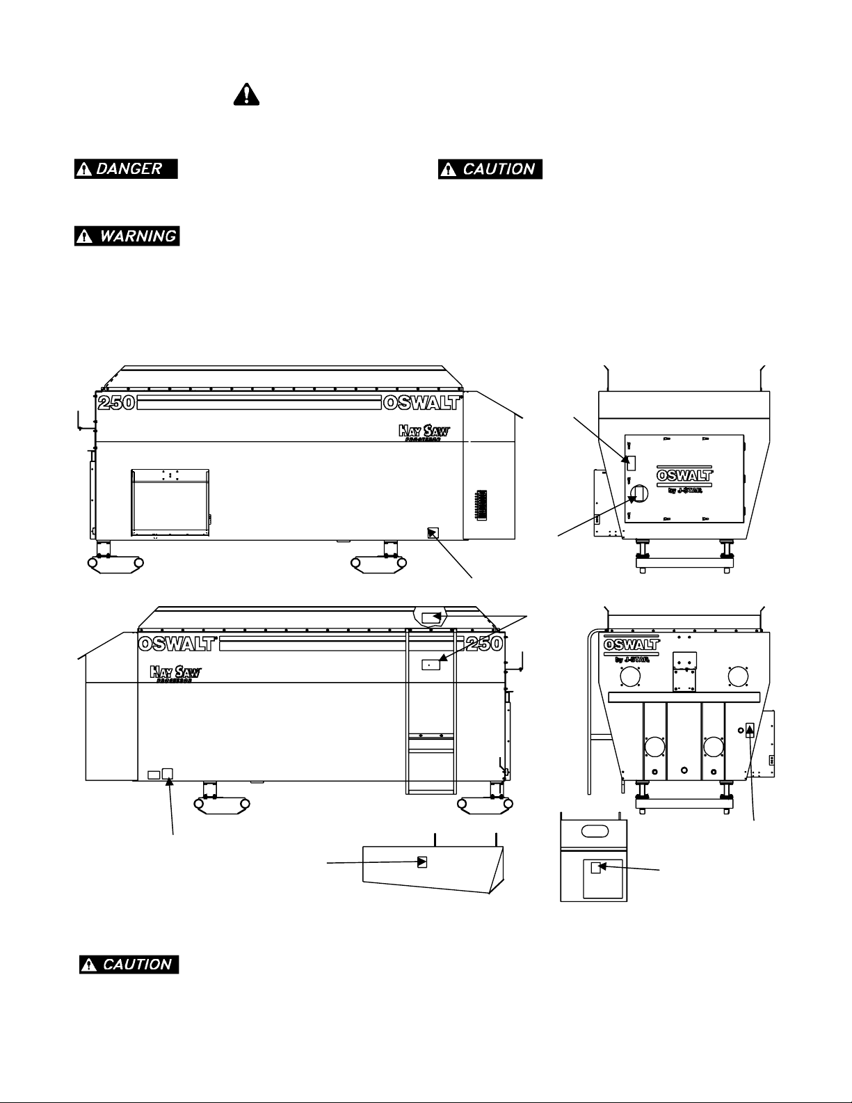
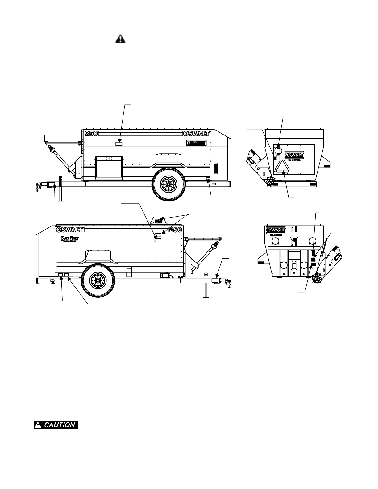
SAFETY DECALS ....................................11
DIMENSIONAL DATA ...................................14
GENERAL INFORMATION .................................15
MIXING CAPACITY ..................................15
ROUGHAGE LENGTH .................................15
USE OF BALED HAY..................................15
LOADING ......................................15
MIXING TIME .....................................16
SHEAR PIN .....................................16
TRACTOR HYDRAULIC SYSTEM
RECOMMENDATIONS .................................16
TRACTOR DRAWBAR .................................16
TRAILER OPERATION ..................................17
PTO ENGAGEMENT ..................................17
CORNERING .....................................17
DISCHARGING FEED .................................17
SCALE SWING MOUNT ................................17
OPTIONAL SINGLE VALVE CONVERSION .........................17
SCALE SYSTEM ...................................17
TRANSPORTING ...................................18
STATIONARY OPERATION.................................19
MOTOR CURRENT ..................................19
DISCHARGING FEED .................................19
ADJUSTMENTS .....................................20
TRAILER ......................................20
TRAILER HITCH CLEVIS ADJUSTMENT (TRAILER MOUNT ONLY) ...............20
STATIONARY ....................................21
STATIONARY AND TRAILER ..............................21
SERVICE JACKSHAFT ASSEMBLY ............................21
DRIVE CHAIN ROUTING ................................22
LUBRICATION ......................................24
TROUBLESHOOTING ...................................25
TRAILER INSTALLATION .................................26
INSTALL CHUTE AND PIVOT BAR ............................26
INSTALLING EXTENDED CONVEYOR
(OPTIONAL) .....................................27
INSTALL OPTIONAL BAFFLE ..............................28
INSTALLING SINGLE PAIR HYDRAULIC VALVE (OPTIONAL) .................29
INSTALLING SCALE INDICATOR.............................30
INSTALLING SCALE TRACTOR SOCKET (SHIPPED WITH MIXER) ...............30
INSTALLING BATTERY ON MIXER ............................31
INSTALLING SCALE SYSTEM ..............................32
INSTALLING MANUAL DOOR OPERATOR .........................35
INSTALLING ELECTRIC DOOR OPERATOR ........................36
INSTALLING TOP GUARD ...............................37
INSTALLING SIDE MOUNT MOTOR ...........................37
INSTALLING SINGLE MOTOR, FRONT MOUNT .......................38
INSTALL DOUBLE MOTOR, FRONT MOUNT ........................38
REPAIR PARTS .....................................39
FINAL FACTORY INSPECTION ...............................72

Page 9
READ ALL SIGNS ON THE MACHINE AND IN THIS MANUAL. REPLACE
ANY LOST OR DAMAGED SIGN BY ORDERING THE PART NUMBERS SHOWN ON THE
SAFETY DECAL PAGE.
SAFETY- STATIONARY MIXER
A brief definition of signal words that may be used in this manual:
Indicates an imminently hazardous
situation that, if not avoided, will result in death or seri-
ous injury.
Indicates a potentially hazardous
situation that, if not avoided could result in death or se-
rious injury, and includes hazards that are exposed
when guards are removed.
Indicates a potentially hazardous
situation that, if not avoided may result in minor or
moderate injury.
K
E
G
D
KE
ON COVER G
ON MOTOR MOUNT
F
(INSIDE DOOR)

Page 10
SAFETY- TRAILER MIXER
READ ALL SIGNS ON THE MACHINE AND IN THIS MANUAL. REPLACE
ANY LOST OR DAMAGED SIGN BY ORDERING THE PART NUMBERS SHOWN ON THE
SAFETY DECAL PAGE.
A
B
C
D
E
F
G
H
J
I
H
L
K
K
K

Page 11
SAFETY DECALS
DECAL A. B157506 DECAL B. 157511
DECAL C. 152545
DECAL D. 154576
DECAL E. 154579 DECAL F. 154583 DECAL G. 154578
DECAL H. 143553 DECAL I. 157509s
DECAL J. 157505
DECAL K. SW104 DECAL L. 157510
NOTE: Complete Decal Kit (all sizes) - 160411

Page 12
MIXER SAFETY
Do not operate your feed mixer until you have read this Owner’s Manual, the Truck Owner’s Manual, and under-
stand the danger associated with its operation.
This feed mixer is comprised of rotating drive shafts and mixing augers. Any exposure to these mixer components
can result in serious personal injury or death.
Study the safety decal page associated with your model mixer and understand where the danger points are.
On truck or trailer mounted mixers, never allow operating personnel to be above the level of the feed mixing cham-
ber. Entry into the mixing chamber while the mixer is running will result in serious injury or death.
ON STATIONARY MIXER MODELS THE TOP PROTECTIVE GRID MUST BE INSTALLED PRIOR TO MIXING
OPERATION AND KEPT IN PLACE. FAILURE TO HEED MAY RESULT IN SERIOUS PERSONAL INJURY OR
DEATH.
THERE ARE INHERENT HAZARDS ASSOCIATED WITH THE OPERATION OF YOUR MIXER.
FOR YOUR SAFETY:
·Do Not Operate, Service, Inspect Or Otherwise Handle This Equipment Unless You Have Read The Owner’s
Manual And Have Been Properly Trained In Its Intended Usage.
·Require All Personnel Who Will Operate This Machinery Or Perform Service, To Read And Understand The
Safe Operating Practices And Safety Precautions In This Manual.
·Do Not Operate Until All Shields, Covers And Guards Are In Place.
·Do Not Allow Children Or Inexperienced Person To Operate This Machine.
·Keep Hands, Feet And Clothing Away From Power Take-off Shaft.
·Do Not Climb On Or Enter Machine While In Operation.
·Do Not Make High Speed Maneuvers With Trailer Mounted Mixer.
·Do Not Allow Riders On A Trailer Mounted Mixer.
FAILURE TO HEED MAY RESULT IN SERIOUS PERSONAL INJURY OR DEATH.

Page 13
THERE ARE ADDITIONAL HAZARDS ASSOCIATED WITH THE SERVICE AND MAINTENANCE OF YOUR
MIXER.
FOR YOUR SAFETY:
·Disengage Power Take-off And Remove Keys From Tractors Before Servicing A Trailer Mounted Mixer.
·Do Not Attempt To Clean, Oil Or Adjust Mixer While It Is In Motion.
·Before Entering Mixing Chamber Or Servicing Stationary Mixer, Disconnect Main Power Source And Lock
The Disconnect Device In Off Position To Prevent Accidental Start-up.
·Do Not Work Under Mixer Without Supporting With Suitable Support Stands.
·Do Not Work Under Mixer Without Blocking Wheels To Prevent Rolling.
FAILURE TO HEED MAY RESULT IN SERIOUS PERSONAL INJURY OR DEATH.

Page 14
DIMENSIONAL DATA

GENERAL INFORMATION
MIXING CAPACITY
Maximum Ration Volume
Model 200 200 cu. ft.
Model 250 250 cu. ft.
Model 300 300 cu. ft.
Model 350 350 cu. ft.
Maximum Ration Weight
(Based on 30 lb/ft3ration)
Model 200 6,000 lb.
Model 250 7,500 lb.
Model 300 9,000 lb.
Model 350 10,500 lb.
Maximum Weight Of Baled Hay
10% of ration by weight.
ROUGHAGE LENGTH
The mixer is designed to mix complete rations including
roughages which fall within the following length limits.
1. At least 75% of the material is 1-1/2 inches or
shorter.
2. Less than 20% of the material exceeds 2-1/2
inches.
3. Maximum fiber length does not exceed 4 inches.
USE OF BALED HAY
Oswalt mixers are designed to blend feed ingredients
with “dry hay” to obtain a total mixed ration. Dry hay
will have less than 20% moisture. A simple hand test
on three stems of hay will tell you if the hay should be
put into the mixer.
Reach into the core of the bale and remove 3 stems of
hay. Try to bend and break these 3 stems when hold-
ing them between the thumb and forefinger of both
hands. If they snap and break easily the mixer will pro-
cess the hay fairly easily. If the hay is NOT very brittle
and you have to twist, tug, pull, and pinch to break it
apart, you have a “tough hay” condition. Weather and
plant varieties, etc., can generate these conditions.
Conditions That Cause Abnormal Tough Hay
·High Moisture Content (20% plus)
·High Density Bales
·High Grass Content
·Outdoor Storage
·Long Stem Length
·Use of Hay Preservatives
FINE STEM GRASS HAY WITH LENGTHS OVER 16
INCHES Are Not Recommended because they tend to
wrap around the augers unless they are extremely brit-
tle.
When in doubt, throw in a half bale of the questionable
feed to insure hay breaks apart and does not wind or
wad.
If, in your judgement, the baled hay quality comes
within the definition of “tough hay” per above, then it’s
recommended you process the bale to shorter length
prior to adding to the mixer.
LOADING
The loading sequence depends on the type of feed be-
ing used. For this reason, we offer a few suggested
loading sequences to maximize mixer performance
and avoid equipment failure.
NOTE: When is doubt, throw in a half bale of the
questionable feed to insure hay breaks apart and does
not wind or wad in the mixer.
For a ration utilizing “dry hay” the ingredients can be
all added at one time and then mixed. The ingredients
should be added with the mixer stopped to avoid over
processing. The ingredients should be added in the
following order: all dry ingredients (corn, soybeans,
cottonseed, etc.) then the hay, and the remaining ma-
terials last. When all ingredients have been added,
the mixer can be started and mixing completed.
If adding all the materials at once causes mixing prob-
lems or if you have a “tough hay” condition, then add
the ingredients using the following sequence. With the
mixer stopped, add all dry ingredients. The introduc-
tion of the dry ingredients first helps the mixer break
up the hay. Next turn on the mixer and add the hay.
Hay should be broken apart and added at the drive
end of the mixer. Allow the dry materials and hay to
mix until the flakes of hay are broken up. Then add
the remaining materials and complete the mixing. If
this process causes over processing of the ingredi-
ents, shut off the mixer after mixing the hay and dry in-
gredients and restart and complete mixing after all
remaining ingredients have been added.
Page 15

If this process causes mixing problems associated with
the hay, then it is recommended that the hay be pro-
cessed to a shorter length prior to adding to the mixer.
A J-Star bale cutter is recommended to accomplish
this.
NOTE: Round bales should not be incorporated di-
rectly into the mixer without first being processed.
MIXING TIME
Normal mixing time after the last ingredient has been
added.
Trailer 5 min. @540 RPM
Stationary 10 minutes
Total run time (filling, mixing, and discharging) should not ex-
ceed 15 minutes per batch for a trailer and 30 minutes for a
stationary. Use of baled hay in the mix will increase the mix
time for a trailer by 5 minutes and a stationary by 10 min-
utes.
SHEAR PIN
The shear pin assembly is located at the back of the
mixer just in front of the oil bath drive housing, see figure
1.
Extra shear bolts are located in a holder on the right
side of the rear structure, see figure 2.
TRACTOR HYDRAULIC SYSTEM
RECOMMENDATIONS
10 GPM Minimum 15 GPM Maximum
1200 to 1600 PSI Operating Range
Hydraulic system should be self purging.
TRACTOR DRAWBAR
See tractor drawbar as shown in figure 3.
Failure to set drawbar properly may
cause shaft to over extend and separate or bend when
cornering or transporting. Resulting in death or per-
sonal injury.
Page 16
FIGURE 1. DRIVE SHAFT SHEAR PIN
(2) 1/4 NUTS
1/4x2 GR5 HEX BOLT*
*NOTE: FIGURE SHOWS SIZE
BOLT NEEDED FOR 200/250.
MODEL 300/350 REQUIRE
1/4x2 GR8 HEX BOLT.
FIGURE 2. SPARE SHEAR BOLTS
SHEAR BOLTS STORED HERE
SIMILAR FOR STATIONARY
FIGURE 3. TRACTOR DRAWBAR

TRAILER OPERATION
PTO ENGAGEMENT
Avoid high speed sudden engagement of the mixer.
Doing so may cause the shear pin to shear.
CORNERING
Sharp cornering with the pto engaged is not recom-
mended. If it is necessary to mix when cornering, it
should be done at reduced speeds and wide corners
only.
DISCHARGING FEED
The discharge door and conveyor tilt are hydraulically
actuated using the tractor’s remote hydraulic system.
The discharge door and conveyor tilt are sequenced
so when the tractor’s remote hydraulic control lever is
moved one way the conveyor will tilt out and the door
will open. The reverse will happen when the lever is
moved in the other direction. Two hydraulic ports on
the tractor are required.
A hydraulic motor is used to run the discharge con-
veyor chain using the tractor’s remote hydraulic sys-
tem. Moving the tractor’s remote hydraulic control one
way will cause the chain to move in the discharge di-
rection. Moving the lever in the opposite direction will
not move the chain due to a check valve in the mixer
hydraulic system. Two hydraulic ports on the tractor
are required.
To discharge feed, move the hydraulic valve lever on
the tractor to open the door and tilt the conveyor. Move
the other lever to start the conveyor chain. Start the
pto. The discharge rate can be controlled by the posi-
tion of the door and the transmission gear selected.
Reverse this sequence when through discharging.
SCALE SWING MOUNT
The scale head is mounted to a swing arm. The swing
arm is designed to allow scale head viewing from ei-
ther side of the mixer or from the tractor just by rotat-
ing the scale arm before loading or unloading starts.
As a convenience a chain is attached to a scale swing
mount. The chain is used to swing the mount arm from
one side of the mixer to the other.
OPTIONAL SINGLE VALVE CONVERSION
This conversion is used when the tractor has only two
remote hydraulic ports. A control valve is mounted on
the mixer and a rope is attached to the valve handle.
Moving the tractor’s remote hydraulic control lever will
start the conveyor chain in motion. With the tractor
lever still moved the rope is pulled to shift the valve on
the mixer. Shifting this valve tilts the conveyor out and
opens the door. To close the door and tilt the conveyor
back the lever on the tractor must be shifted opposite
and the rope pulled.
SCALE SYSTEM
Refer to the operation book supplied with the scale in-
dicator head.
Page 17

TRANSPORTING
A safety chain should be installed to
retain the connection between the tractor (or other
towing vehicle) and mixer if the hitch connection would
separate; whenever traveling on highways. A sug-
gested attachment is illustrated on figure 4.
The chain must be strong enough to hold the weight of a
loaded mixer. If using a grab hook at the end to secure
the chain to itself, a hook latch must be installed as illus-
trated.
The length of the safety chain is not to be any longer than
necessary to turn without interference. If any chain lengths
or attachment hardware are broken or stretched, repair
before using. Store chain so it does not corrode or be-
come damaged. Do not use this chain for other imple-
ments because the strength and length of chain may not
be adequate. Identify this chain for use on this particular
mixer.
The ratio of the loaded mixer weight compared to the
weight of the towing tractor or other vehicle must not
be greater than 1.50.
Page 18
FIGURE 4. SAFETY CHAIN INSTALLATION
INTERMEDIATE
SUPPORT
(NOT SUPPLIED)

STATIONARY OPERATION
MOTOR CURRENT
An ammeter should be installed in the line where it can
monitor motor current. It may be necessary to adjust
the amount of feed that is processed in the mixer to
obtain an amp draw equal to or less than the full load
motor current rating.
DISCHARGING FEED
Manual Operator
To open the discharge door, first pull back on the lock
pin, see figure 5. This pin is positioned close to the
hand wheel hub. With the pin pulled back turn the pin
handle 90 degrees and release. The pin will now stay
disengaged and the hand wheel can be turned to the
desired open position.
When the door is open far enough, turn the pin handle
back 90 degrees and rotate the hand wheel until the
pin drops into the nearest lock hole.
Electric Door Operator
A electric motor drive linear actuator opens and closes
the mixer discharge door. The actuator motor is con-
trolled by a dealer installed switch. Moving the switch
in one direction opens the door and in the other direc-
tion closes the door. The middle position is off, keep-
ing the door in the current position. The actuator can
be stopped in any position to control the flow of feed.
The actuator will “free wheel” at each end of its total
stroke.
NOTE: Always open and close discharge door with the
mixer running. This will prevent high material pressure
against the door which may stall out the actuator mo-
tor.
SCALE SYSTEM
Refer to the operation book supplied with the scale in-
dicator head.
Page 19
FIGURE 5. HAND WHEEL
PIN
PIN
HAND WHEEL LOCKED
HAND WHEEL FREE TO SPIN
PULL BACK AND TURN 90°

ADJUSTMENTS
TRAILER
Discharge Conveyor Height
The discharge chute height can be set by positioning
the stop pin in the desired hole of the fold limiter bar,
see figure 6.
Discharge Chute Folding
Folding of the discharge chute is controlled by the ad-
justment of the threaded pivot on the side of the con-
veyor and position of the spring underneath the
conveyor, see figure 7.
Threading the pivot out of the end of the pivot bar will
make the chute fold closed more when the conveyor is
tilted up for storage. Threading the pivot into the pivot
bar will cause the chute to fold down more when dis-
charging feed. If the chute does not rotate down when
conveyor is lowered, move the spring mount so the
spring is stretched longer.
Conveyor Drive Chain
There are adjusting nuts on each side of the conveyor.
Tighten or loosen these nut to allow approximately
1-1/4 inches between the bottom of the chain flight and
the conveyor pan when the chain is pulled up at the
center of the conveyor, see figure 8.
Trailer Hitch Clevis Adjustment (trailer
mount only)
NOTE: 350 Only
Mixer should be approximately level when attached to
the tractor.
Adjust clevis by changing hole location on tongue.
Hitch Pin Size - 1” x 6”
Page 20
FIGURE 6. ADJUST DISCHARGE HEIGHT
FOLD LIMITER BAR
STOP PIN
FIGURE 7. FOLD DISCHARGE CHUTE
SPRING
DISCHARGE CHUTE
PIVOT BAR
THREADED PIVOT
ALWAYS DISCONNECT AND LOCKOUT ELECTRICAL POWER (STATIONARY MODELS) OR DISENGAGE POWER
TAKE AND REMOVE KEYS FROM TRACTOR (TRAILER MODELS) BEFORE CLEANING, ADJUSTING, LUBRICAT-
ING OR SERVICING THIS MACHINE. FAILURE TO HEED MAY RESULT IN SERIOUS PERSONAL INJURY OR
DEATH.
FIGURE 8. ADJUST CONVEYOR CHAIN
(2) ADJUSTING NUTS
This manual suits for next models
3
Table of contents
Other Roto-Mix Mixer manuals
Popular Mixer manuals by other brands

Altrad
Altrad PROMIX 1400 Original instructions, safety instructions, spare parts

Bazooka
Bazooka MPA1000 installation guide

Hamilton Beach
Hamilton Beach CPM700 - Commercial Stand Mixer Operation manual

pampered chef
pampered chef 100833 manual

Tascam
Tascam US-224 Use guide

Behringer
Behringer X AIR XR16 quick start guide