rotork Paksan P3F User manual

Publication S703E V1.1 Issue 06/09
P3F - PAKSCAN FIELD MOUNT
MASTER STATION
TECHNICAL MANUAL

P3F - Pakscan Master Station Technical Manual
2 of 82 Publication S703E V1.1 Issue 06/09
KNOW YOUR MASTER STATION
Future
option slot
CPU
Module
Host Comms Serial
Ports 1 and 2
Current Loop
option
Power
Supply
Power
Connector
View with door open
Current
Loop
Connector
Alarm and
ESD
Terminals DIN Rail
Host
Ethernet
Port 3
Earth
Stud
Host
Ethernet
Port 4
Service
Ethernet
Port
Mounting
Brackets

Contents
3 of 82 Publication S703E V1.1 Issue 06/09
Contents:
KNOW YOUR MASTER STATION.............................................................................2
INTRODUCTION.........................................................................................................5
1. MOUNTING AND CONNECTING THE MASTER STATION..............................7
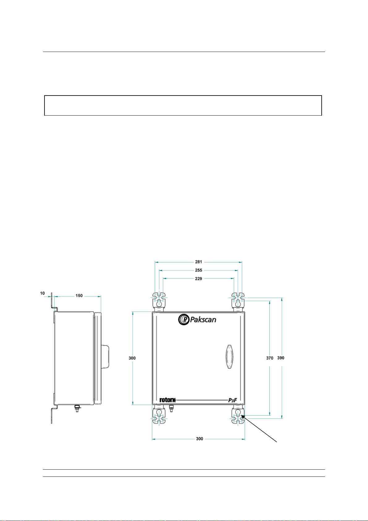
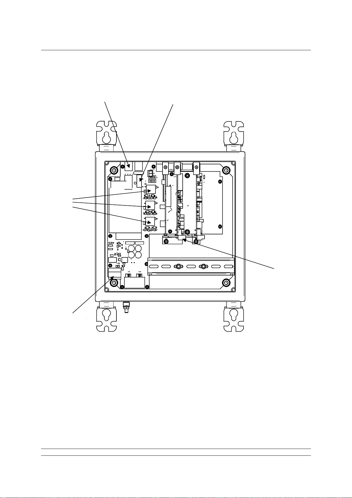
1.1 Mechanical Fixing...................................................................................................................7
1.2 Serial Comms Connections ...................................................................................................8
1.3 Ethernet Comms Connections ..............................................................................................8
1.4 Power Connector and Fuse....................................................................................................8
1.5 ESD and Alarm Output Connector........................................................................................9
1.6 Current Loop Connections.....................................................................................................9
2. THE FIELD NETWORK....................................................................................11
2.1 Loop Checks..........................................................................................................................11
2.1 Loop Checks..........................................................................................................................12
2.2 Connecting Up.......................................................................................................................12
3. SORTING OUT THE SERIAL COMMS LINKS.................................................15
3.1 Setting Port 1 and 2 for RS232 or RS485............................................................................15
3.2 When to Use RS232 ..............................................................................................................17
3.3 When to Use RS485 ..............................................................................................................17
4. USING ETHERNET HOST COMMS.................................................................19
4.1 Setting-Up the Ethernet Comms..........................................................................................19
5. THE INTERNAL WEB PAGES.........................................................................21
5.1 Making an Internet / intranet Connection...........................................................................21
5.2 Connecting a Laptop Directly to the Master Station .........................................................21
5.3 5.3 Adjusting the Network Settings of the Laptop / PC....................................................21
5.3 5.3 Adjusting the Network Settings of the Laptop / PC.....................................................22
5.4 Web Page Structure..............................................................................................................23
5.4.1 User Levels.........................................................................................................23
5.4.2 Overall Web Page Layout...................................................................................23
5.5 The Web Pages in Detail.......................................................................................................25
5.5.1 Log In Screen .....................................................................................................25
5.5.2 Master Station ....................................................................................................25
5.5.2 Master Station ....................................................................................................26
5.5.3 View Configuration .............................................................................................28
5.5.4 System Diagnostics............................................................................................29
5.5.5 Master Station Data Logger................................................................................30
5.5.6 Master Station Host Analyser.............................................................................32
5.5.7 Pakscan 2 Loop Diagnostics..............................................................................33

P3F - Pakscan Master Station Technical Manual
4 of 82 Publication S703E V1.1 Issue 06/09
5.5.8 Option Card Event Logger..................................................................................36
5.5.9 FCU Menu ..........................................................................................................37
5.5.10 FCU Control - IQ/IQT Actuator...........................................................................38
5.5.11 FCU Control - Integral Actuator..........................................................................43
5.5.12 FCU Control - Flowpak Actuator.........................................................................47
5.5.13 FCU Control - General Purpose Field Unit.........................................................49
5.5.14 FCU Control - Other Field Units .........................................................................52
5.5.15 Admin..................................................................................................................54
5.5.16 Users ..................................................................................................................54
5.5.17 Masterstation Config...........................................................................................57
5.5.18 Host Port Configuration......................................................................................61
5.5.19 Alarms.................................................................................................................64
5.5.20 Time....................................................................................................................66
5.5.21 General...............................................................................................................67
5.5.22 Network...............................................................................................................68
5.6 Setting Up the Master station Configuration Using the Web Pages................................70
5.6.1 Master Station Set-up page................................................................................70
5.6.2 Option Module Set-up (including host comms protocols)...................................72
5.6.3 Host Port Settings...............................................................................................72
5.6.4 Setting the IP Address........................................................................................73
6. MAKING THE SYSTEM WORK .......................................................................75
6.1 Commissioning the System.................................................................................................75
6.2 Monitoring and Controlling the Actuators..........................................................................76
GENERAL SAFETY INFORMATION........................................................................79

Introduction
5 of 82 Publication S703E V1.1 Issue 06/09
INTRODUCTION
Pakscan 3 is the latest network control system from Rotork. The Pakscan P3F master station
encompasses the P3 technology in a master station specifically designed for mounting in remote
locations. The P3F enclosure protects the electronics within to IP65 standards and is suitable for use
in those locations where more conventional equipment cannot be located. Compared to the P3, the
P3F is simplified to include only those features demanded by smaller and simpler applications. It is a
single channel system capable of supporting up to 32 actuators or other field units.
Most types of Rotork actuator can be connected to the Pakscan current loop provided they are fitted
with the necessary field unit. Information on the respective actuator field units can be found in the
appropriate manuals. In this guide, the type of actuator is not considered, though reference is made to
both the Integral and IQ actuator types of field unit. The type of field unit does not affect the setting up
of the system.
The P3F master station is supplied as a stand alone unit ready for connection to the actuators and
host control system.
This manualrelates to Pakscan P3F Master Stations
fitted with PS720 Current Loop modules
Fig 1: The Pakscan P3F Master Station

P3F - Pakscan Master Station Technical Manual
6 of 82 Publication S703E V1.1 Issue 06/09
(This page is intentionally blank)

Mounting the Master Station
7 of 82 Publication S703E V1.1 Issue 06/09
1. MOUNTING AND CONNECTING THE MASTER STATION
The Pakscan P3F master station provides front access for all the user connections including power
feed and the field loop wires to the Current Loop module (PS720). The host communication uses
screw terminal connections for the serial comms and RJ45 connections for the Ethernet links.
The field wiring for the loop and the master station alarms is taken to screw terminals on plug
in connectors that are fitted from below their appropriate module.
Power wiring is connected using a 3-way plug-in connector with screw terminals in the top of
the master station main circuit board.
Serial comms ports 1 and 2 (RS232 or RS485) connect to an 8-way plug-in connector with
screw terminals on the bottom of the main circuit board.
Ethernet connections use RJ45 connectors on the main circuit board. The service port
connector is intended for connection to a service laptop computer. Host ports 3 and 4 are for
permanent Ethernet connections.
1.1 Mechanical Fixing
.
Before fixing the master station in its permanent location, it may be more convenient to set the
comms link switches as discussed in section 3.
Fig 2: Pakscan 3F surface mounting dimensions.
All dimensions in mm
Hinge on left side of
enclosure
Holes for M8
fixing bolts

P3F - Pakscan Master Station Technical Manual
8 of 82 Publication S703E V1.1 Issue 06/09
Room should be left around the enclosure for all the connections and cables, allowing for suitable
bending radius on each lead. Power wiring should be suitably fused or protected with a miniature
circuit breaker (MCB) external to the master station.
The master station should be mounted on a flat surface using the mounting brackets provided. It
should be located in a way that permits easy opening of the front door and access to the internal
connectors and modules.
1.2 Serial Comms Connections
The serial data connections are via the Serial Comms terminal block located on the main circuit board
below the power supply and to the left of the DIN rail. This connector has screw terminals and plugs in
to the mating part fixed on the circuit board. The terminal connections are shown below.
Terminal RS232
Connections RS485
Connections
1 TX
2 RX Data -
3 GND GND
4
Port 1
Data +
5 TX
6 RX Data -
7 GND GND
8
Port 2
Data +
With RS485 it is possible to arrange a multi-drop data highway for the serial communications,
whilst RS232 must be single point comms.
1.3 Ethernet Comms Connections
Each Pakscan P3F master station has 3 x RJ45 Ethernet connectors for the host communication ports
and the service port. These are marked Port 3 and Port 4 (host communication ports) and Port 5
(service port). A portable computer (laptop) should be connected to Port 5, the service port, to set up
the P3F. Standard Ethernet shielded patch cables should be used with these ports.
1.4 Power Connector and Fuse
The Pakscan P3F has its own internal power supply and a three-way screw terminal connector at the
top of the main circuit board is provided to allow the mains power (85 to 265V AC – 47 to 63 Hz) to be
connected. The master station power fuse is located just below this connector and should be 250V 1A
fuse. For the 24V DC version the same three-way connector is used.
Fig 3: Serial Comms connector terminal functions
4
1
2
3
8
5
6
7
Port 1
Port 2

Mounting the Master Station
9 of 82 Publication S703E V1.1 Issue 06/09
Terminal ac Connection
(85-265V ac) dc Connection
(18-36V dc)
1 N (Neutral) 0 V
2 L (Line) 24 V
3 E (Earth) Earth
1.5 ESD and Alarm Output Connector
There is a removable screw terminal connector plugged into the main circuit board of the P3F master
station for the connection of ESD hard-wired inputs and for connection to the internal alarm relay
contacts, when required. (On most systems these terminals will not be used; in which case a hard-
wired link between pins 4 and 5 should be added.)
Note that the relay is shown in the ‘Alarm Active’ or ‘power removed’ position.
1.6 Current Loop Connections
A removable screw terminal connector is located in the bottom of the Current Loop Module for the
connection of the Pakscan IIE current loop to the field mounted actuators.
Terminal Function
1 Alarm (common)
2 Alarm (normally closed)
3 Alarm (normally open)
4 Emergency Shutdown
5 Emergency Shutdown
Terminal Function
1 Port B In
2 Port B Out
3 Port B Screen
4 Port A In
5 Port A Out
6 Port A Screen
Fig 5: Alarm/ESD connector terminal functions
Fig 6: Current Loop connections
Alarm
5
4
1
2
3Emergency
Shutdown
PS710
CONNECTOR
Fig 4: Power connector terminal functions
1
2
3
Power

P3F - Pakscan Master Station Technical Manual
10 of 82 Publication S703E V1.1 Issue 06/09
Power
Connector
Ethernet
Ports
Hard Wired
ESD
Serial
Ports
Current
Loop
Fuse
Fig 7: View of the Pakscan P3F master station showing the Connectors and Fuse

Field Network
11 of 82 Publication S703E V1.1 Issue 06/09
Port A
OUT = Term'l 5
IN = Term'l 4
Port B
IN = Term'l 1
OUT = Term'l 2
Up to 32 actuators
per loop
Current loop
- up to 20 km
2. THE FIELD NETWORK
The Pakscan current loop field network must be correctly cabled and connected to the master station.
The values of the field loop resistance and capacitance must be known to determine the loop speed
that can be used. If these are not known then the LOWEST loop speed must be set in each actuator
and the master station to ensure some field network connectivity.
Fig 8: Pakscan P3 Network

P3F - Pakscan Master Station Technical Manual
12 of 82 Publication S703E V1.1 Issue 06/09
2.1 Loop Checks
The most common errors in installing the system occur on the field wiring.
Loop Continuity
With all the field units connected, but none of them powered up, check the continuity of the 2
cores of the cable and measure its resistance.
Screen Continuity
Make sure that the screen is isolated from the loop cores and that the screen is continuous.
Ensure the screen is connected to a signal earth bar at only one point or to terminals on the
loop driver plug; 3 linked directly to the enclosure earth and 6 linked to the enclosure earth via
an internal capacitor. Both the screens must be connected to the terminals provided, so as to
ensure the product meets the European Directive on EMC.
Cable Capacitance
The capacitance between the cores, and to the screen, is critical to the system performance.
Too high a capacitance for the selected loop baud rate will result in poor communications, or
even communication failure.
Maximum Loop Speed
The cable resistance and capacitance must not exceed the permitted maximum values for each
communication speed. The limiting values of R and C for each speed will depend on the
number of field units actually connected. The following table gives the total figures for systems
including the capacitance of the field units. Deduct 2.2nF for each field unit to determine the
maximum cable capacitance allowed at each speed.
Baud Rate R max (ohms) C max (μF)
110 500 4.5
300 500 2.1
600 500 1.54
1200 500 0.6
2400 500 0.3
Each field unit will add a capacitance of 2.2nF (0.0022µF)
The C max figure given is the maximum value for the network capacitance
including the field unit capacitance.
2.2 Connecting Up
Once the checks are complete, connect the Loop Cables to the PS720 Current Loop module. At this
point leave the actuators all without power except for the one furthest from Loop Port A.
Refer to section 6 for commissioning a Pakscan system.

Field Network
13 of 82 Publication S703E V1.1 Issue 06/09
PROCESSORS
AND
COMMUNICATIONS
SERIAL
PORT 1
SERIAL
PORT 2
POWER
SUPPLY
MAINS
SUPPLY
LNE
PS 720 MODULE
(CURRENT LOOP
CONTROLLER)
ETHERNET
PORT 3
ETHERNET
PORT 4
Port A OUT
If there is a signal earth bar, connect the
screen on one side only to the bar
SIGNAL EARTH BAR
Port A IN
Screen
ABCSCR
Port B OUT
Port B IN
AB
CSCR
Actuator Terminals
ABC SCR
EMERGENCY
SHUTDOWN
Screen
5
4
6
2
1
3
5
4
ALARM
1
2
3
Actuator Terminals
ActuatorTerminals
123
ETHERNET PORT 5
(CONFIGURATION)
Fig 9: Pakscan P3F Current Loop System Block Diagram
Note: If there is no hard-wired ESD requirement, a shorting link must be fitted across pin 4
and 5 of the 5 pin plug.

P3F - Pakscan Master Station Technical Manual
14 of 82 Publication S703E V1.1 Issue 06/09
(This page is intentionally blank)

Serial Comms Links
15 of 82 Publication S703E V1.1 Issue 06/09
3. SORTING OUT THE SERIAL COMMS LINKS
The Pakscan P3F CPU module has two serial ports. Each of these is configurable for RS232 or
RS485. Where redundant communications to the host system using serial comms is required, then
two RS485 connections are often used.
3.1 Setting Port 1 and 2 for RS232 or RS485
The main circuit board has DIP switches for setting the type of serial port that is presented at the port
terminal block.
Fig 10: Pakscan P3F Serial related switches
Select Port 2
Function
Select RS485
Termination
Select Port 1
Function

P3F - Pakscan Master Station Technical Manual
16 of 82 Publication S703E V1.1 Issue 06/09
Port Function
The two DIP switches allow each port to be selected between RS232 and RS485. For RS485
slide the appropriate Port switch up, for RS232 they should be down.
Each of the two ports may be set independently.
Port Termination Resistors
The two DIP switches are used to connect end of line termination resistors and biasing resistors
to the RS485 network. All RS485 network highways should be terminated at both ends of the
highway. Each port can be terminated independently.
Fig 11: Port Function Switches shown in RS232 position
Fig 12: Port Termination Switches shown in Off position
1k
1k
120

Serial Comms Links
17 of 82 Publication S703E V1.1 Issue 06/09
3.2 When to Use RS232
When the host PLC or DCS is located near to the Pakscan P3F master station, RS232 comms can be
used with single point to point links. Either Port 1 or Port 2 can be used, though most users would use
Port 1. Two links can be used if redundant communications are required.
For RS232 on - Port Terminations RS232 RS485
Port 1 Off (Down) RS232 (Down)
Port 2 Off (Down) RS232 (Down)
3.3 When to Use RS485
When there are several Pakscan P3F master stations to be connected to the PLC, or the distance
between the Host and the master station is more than 20 metres, an RS485 highway will be best. The
highway will require a multi-drop configuration, as shown on the diagram. The screw connectors in
Fig 13: RS232, dual highway, from P3F master station to PLC
Fig 14: RS485, dual highway, from P3F master stations to PLC
PLC
Pakscan P3F Master Station
Pakscan
P
3
rotork
P
3
F
Highway 1 – RS232
Highway 2 – RS232
Pakscan P3F Master Stations
Highway 2 - RS485
Highway 1 - RS485
PLC
Pakscan
P
3
rotork
P
3
F
Pakscan
P
3
rotork
P
3
F

P3F - Pakscan Master Station Technical Manual
18 of 82 Publication S703E V1.1 Issue 06/09
the master station make this simple to achieve. When a multi-drop connection is made, care must be
taken to ensure that the cable is not broken if a master station is disconnected.
The master station supplies port termination resistors for each port, which can be enabled where
required.
For RS485 on - Port Terminations RS232 RS485
Port 1 Off (Down)
On (Up) RS485 (Up)
Port 2 Off (Down)
On (Up RS485 (Up)

Ethernet Comms Links
19 of 82 Publication S703E V1.1 Issue 06/09
Switch
Ethernet Highway 1
Ethernet Highway 2
Pakscan 3F Master Stations
PLC Port 3 Port 4 Port 3 Port 4
Switch
Pakscan
P
3
rotork P3F
Pakscan
P
3
rotork P3F
4. USING ETHERNET HOST COMMS
Pakscan P3F master stations come complete with two Ethernet ports for connection to host DCS or
PLC systems. A third Ethernet port is also available for connection to a laptop computer for
configuration purposes. The master station is ready to use with Ethernet and Modbus TCP protocol for
the DCS to access data and control the actuators on the field network. The IP address is already set
and can be changed during setting up the master station
4.1 Setting-Up the Ethernet Comms
Ethernet connections require 10BaseT or 100baseT Ethernet Switches to connect the system
together. Patch cords connect the ports on the master to the Switches. Independent highways are
possible by using separate switches on each highway.
The Pakscan P3F master station defaults to the same IP address on both the ports. It is possible to
change the IP address, but the two ports always have the same address.
DHCP Static
Default IP address 10 200 1 1
Subnet mask 255 255 255 0
Fig 15: Ethernet, dual highway, from P3F master station to PLC
Pakscan P3F Master Stations

P3F - Pakscan Master Station Technical Manual
20 of 82 Publication S703E V1.1 Issue 06/09
The recommended highway organisation is:
Use two main data highway bus’s, each of which connects to all the master stations.
The master is left with a Static DHCP port setting.
The master station can serve up to 10 simultaneous host connections.
With this arrangement either PLC port can always communicate with the master station and the
devices on the loop. Heartbeat data requests on the second highway will always be acknowledged
with a response.
Table of contents
Other rotork Control System manuals
Popular Control System manuals by other brands

Distech Controls
Distech Controls EC-BOS-6AX Mounting and wiring instructions

WORKSWELL
WORKSWELL THERMOINSPECTOR user manual

Inspire
Inspire ignite manual

aldes
aldes Dee Fly Cube 550 Installation and maintenance instructions

Cattron
Cattron EliteIQ quick start guide

BIOS
BIOS Professional 200TC instruction manual

BERNSTEIN
BERNSTEIN CS-480 Installation and operating instructions

BFT
BFT STOPPY MBB 219-500.C Instructions for installation, use and maintenance

Fireye
Fireye BurnerPRO manual

Badger Meter
Badger Meter AR/e Installation & operation manual

Mitsubishi Electric
Mitsubishi Electric TC-24A installation manual

Mitsubishi Electric
Mitsubishi Electric AE-200A Instruction book