Royal Enfield EURO IV User manual

EURO IV - ENGINE SERVICE MANUAL

ROYAL ENFIELD UCE ENGINE SERVICE MANUAL 1
PREFACE
Part No. 888571 / Dec. ‘ 16
“FIRST TIME RIGHT” is a very important element for ensuring customer satisfaction.
This Service Manual is published to help technician carry out repairs on Royal Enfield Motorcycles in a scientific manner.
This service manual is created for the following Euro IV models sold in UK & European countries.
BULLET EFI
BULLET CLASSIC EFI
CONTINENTAL GT
This manual will help guide in the basic servicing, periodical maintenance, systematic disassembly, Parts inspection
and assembling procedures of various mechanisms / systems of the motorcycle.
This Manual is intended for use primarily by a person who is well versed with basic repair techniques of a motorcycle,
usage of general purpose, special tools & diagnostic tools. While basic & routine maintenance can be carried out with
geneal purpose tools, it will require the technician to have special tools & diagnostic equipments to attend to major
jobs diagnosis of Engine Management System.
In the event of non availability of any special tool or Royal Enfield NACS II Diagnosis tool, it is recommended that the
motorcycle may please be taken a nearest Royal Enfield Authorised Service Station for a detailed investigation &
proper attention.
While this manual is updated with latest Information and Specifications, at the time of going to print, due to continuous
improvements being done to improve performance, some of the data, illustrations etc., in this manual may differ
from the actual parts fitted in the engine.
Subsequent & continuous improvement that may be done on the motorcycles to enhance customer satisfaction, will
be uploaded in the RMI portals & also available with Royal Enfield Authorised dealer & Service Station.
This manual is specifically made for the Unit Construction Engine and has to be read in conjuction with the vehicle
Service Manual for attention to Engine Management System, induction & exhaust system.
Please do feel free to write to us atsupport@royalenfield.com, if you have any queries, clarification, suggestions or
feedback.
With warm regards
SERVICE HEAD QUARTERS
Royal Enfield, A Unit of Eicher Motors Limited,
Thiruvottiyur High Road, Thiruvottiyur, Chennai - 600 019.
E-mail: Support@royalenfield.com
Website: www.royalenfield.com
ROYAL ENFIELD UCE ENGINE SERVICE MANUAL 01

ROYAL ENFIELD UCE ENGINE SERVICE MANUAL
2
CONTENTS
ROYAL ENFIELD UCE ENGINE SERVICE MANUAL
02
1. Engine views ............................................................................ 3
2. Technical Specifications .........................................................4
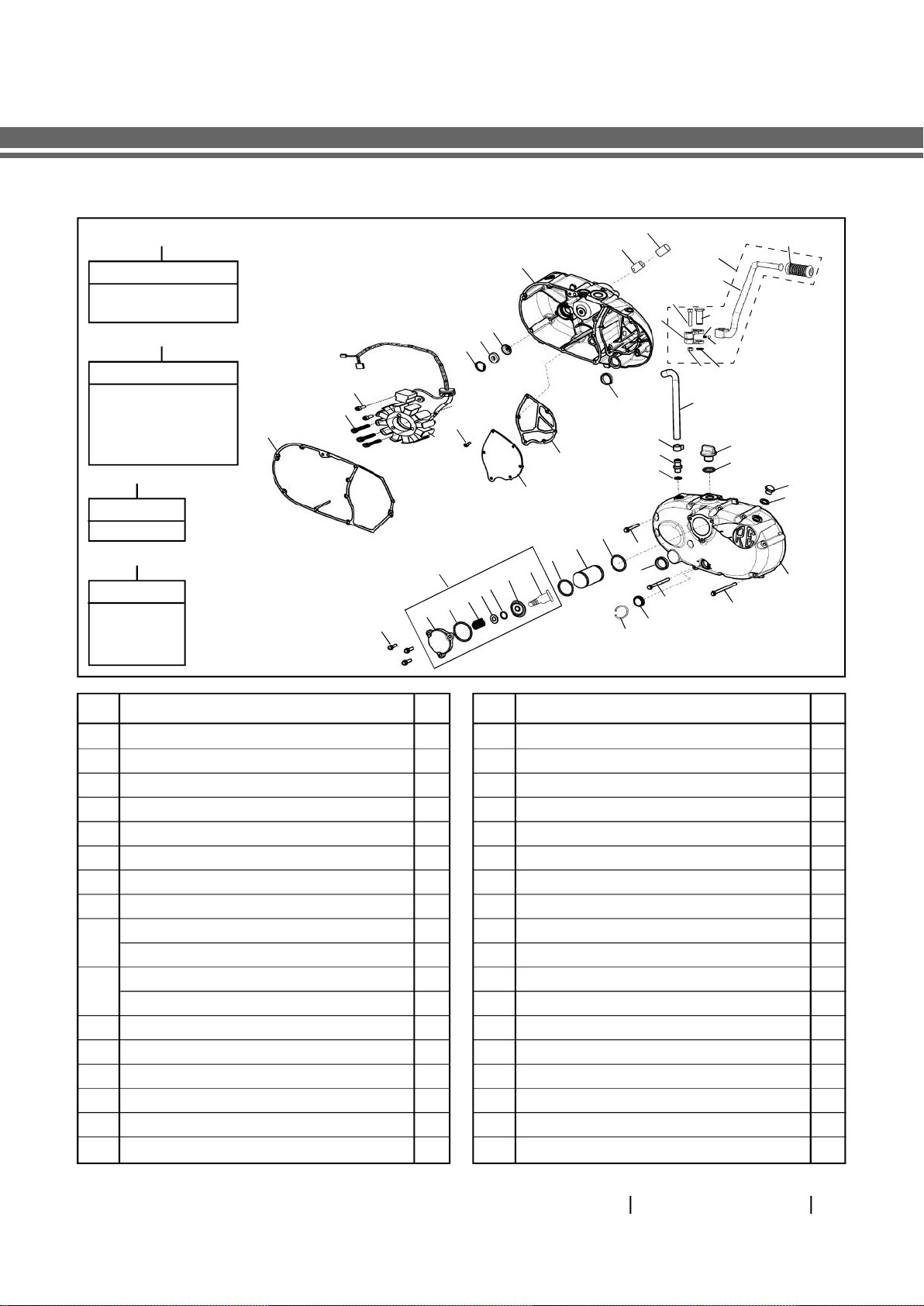
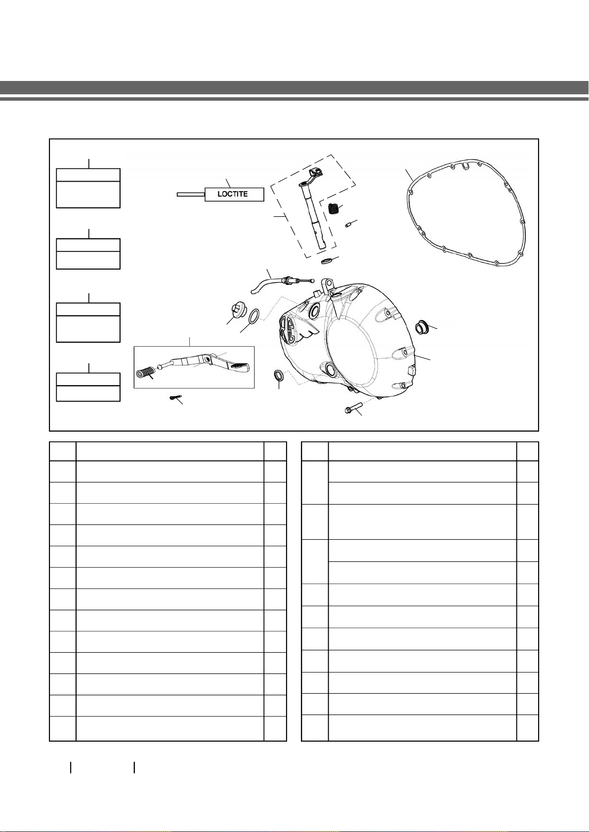
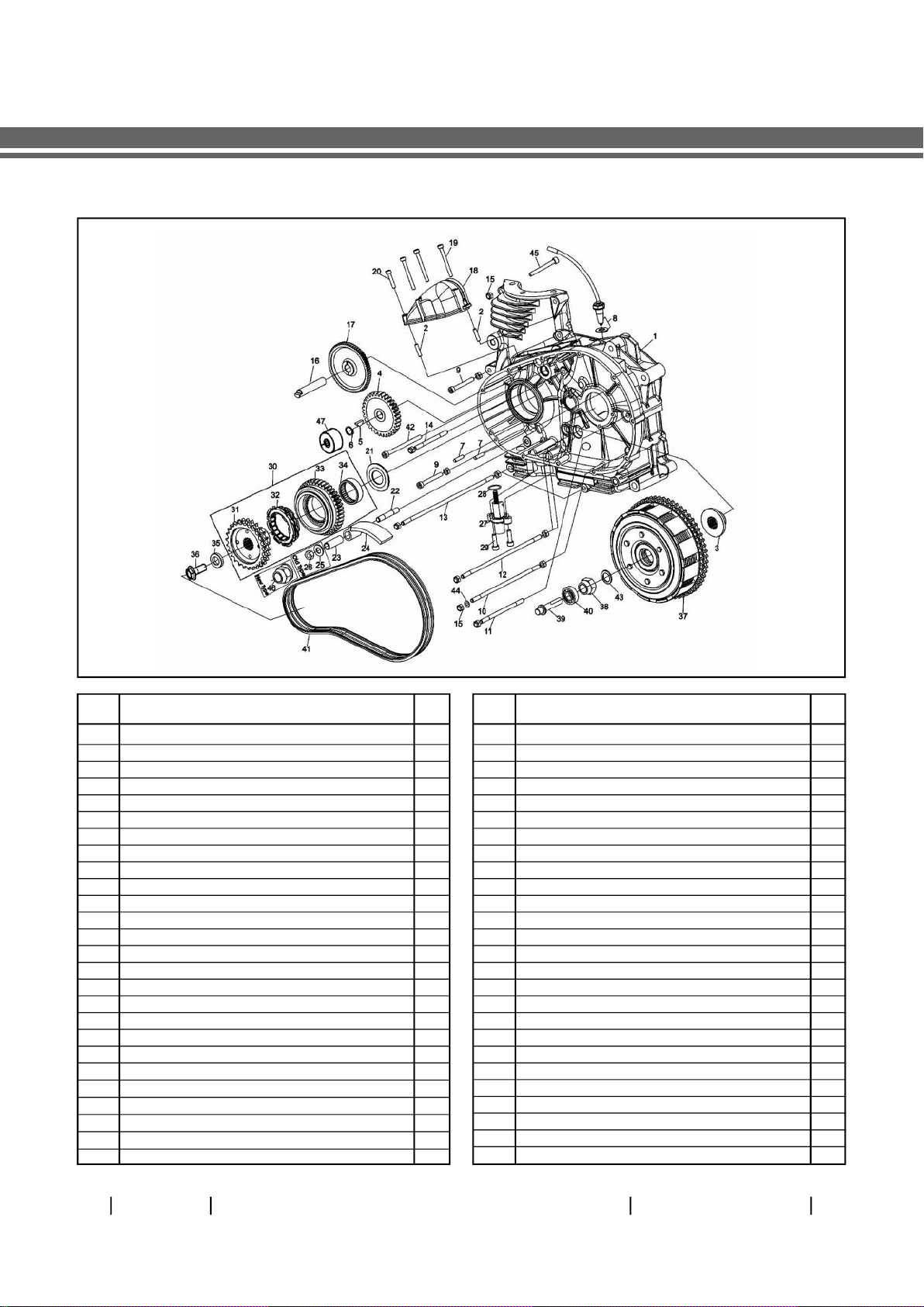
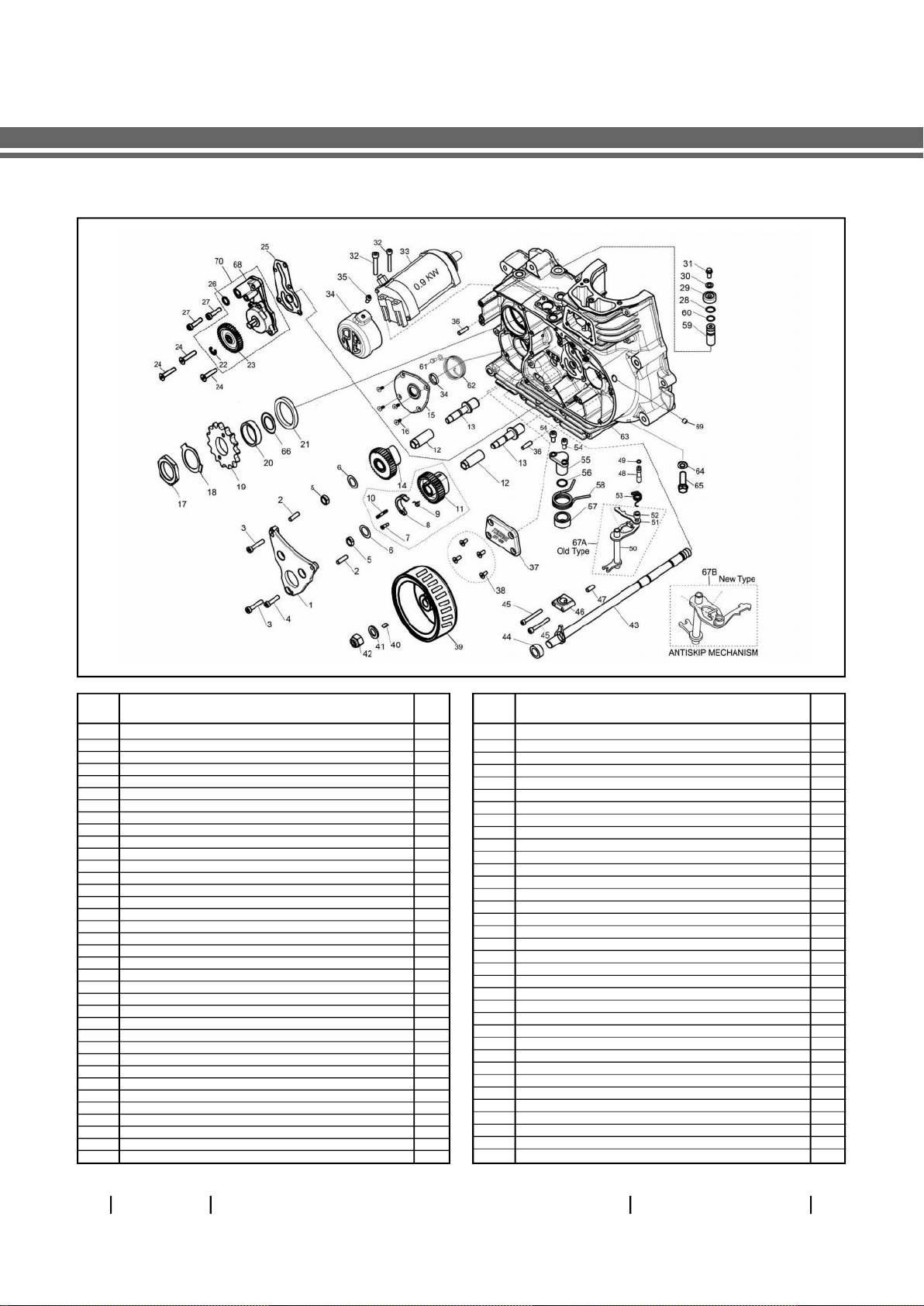
3. Exploded Views ....................................................................... 5
4. Gear Operating Positions .....................................................10
5. Lubrication System ................................................................ 11
6. Periodical Maintenance Chart ..............................................13
7. Special Tools Usage List ........................................................ 14
8. Engine Dismantling Sequence .............................................15
8.1 Engine oil Drain ........................................................... 16
8.2 Cylinder Head ...............................................................17
8.3 Dismantling Inlet & Exhaust Valves .......................... 19
8.4 Cylinder barrel / piston ............................................. 20
8.5 Starter motor & housing ............................................22
8.6 Removal of RH Cover .................................................23
8.7 Removal of Rotor Assembly ...................................... 27
8.8 Cam steady plate & cam gears .................................. 28
8.9 Auto Decompressor .................................................. 29
8.10 Oil Pump ..................................................................... 30
8.11 Gear Shift assembly removal ......................................31
8.12 F.D. Sprocket ................................................................ 33
8.13 Kick Starter ...................................................................35
8.14 Cover LH ...................................................................... 36
8.15 Clutch Assembly ........................................................ 38
8.16 Sprag Clutch Assembly ............................................. 40
8.17 Dismantling of Clutch Assembly .............................. 41
8.18 Auto Chain Tensioner ............................................... 43
8.19 Starter Double Gear ................................................... 44
8.20 Crankcase LH & RH..................................................... 45
8.21 Gear Train Removal ................................................... 50
8.22 Hydraulic Tappets ....................................................... 53
8.23 Layshaft ...................................................................... 54
8.24 Mainshaft.....................................................................55
8.25 Sleeve Gear ..................................................................57
8.26 Kick Starter .................................................................. 58
8.27 Kick Starter Shaft ........................................................ 59
9. Uni Directional Fittings List .................................................. 61
10.Inspection ............................................................................. 62
11. Torque Chart ......................................................................... 78
12. Engine Assembling Sequence ............................................80
12.1 Engine Bearings Crankcase LH .................................. 81
12.2 Engine Bearings Crankcase RH................................. 83
12.3 Kick Starter sub Assembly ........................................ 85
12.4 Kick Starter shaft ........................................................ 86
12.5 Layshaft Sub Assembly ............................................. 88
12.6 Mainshaft Sub Assembly .......................................... 90
12.7 Hydraulic Tappets ...................................................... 98
12.8 Drain Plug ................................................................. 100
12.9 Gear Train................................................................... 101
12.10 Gear Rocker Shaft on Crankcase RH outer .............102
12.11 Crankcase LH & RH ....................................................105
12.12 Starter Double Gear ................................................. 108
12.13 Auto Chain Tensioner ............................................. 109
12.14 Sprag Clutch Assembly ............................................ 110
12.15 Sub Assembly of Clutch Plates .................................. 111
12.16 Assembly of Clutch ................................................... 113
12.17 Cover LH ...................................................................... 115
12.18 FD Sprocket ................................................................118
12.19 Gear Shift Assembly .................................................. 119
12.20 Oil Pump ....................................................................120
12.21 Auto Decompressor .................................................. 121
12.22 Assembly Procedure of Cam Gears .......................... 122
12.23 Assembly of Rotor Assembly .................................. 128
12.24 Assembly of RH Cover ............................................... 131
12.25 Starter motor & housing .......................................... 133
12.26 Cylinder Barrel/Pistion ............................................. 134
12.27 Piston Ring Sub Assembly ....................................... 135
12.28 Assembly of Inlet /Exhaust Valves.......................... 136
12.29 Cylinder Head Assembly.......................................... 138
12.30 Engine Oil Filling ...................................................... 140
13. Trouble Shooting .................................................................141
SL.NO. DESCRIPTION PG.NO. SL.NO. DESCRIPTION PG.NO.

ROYAL ENFIELD UCE ENGINE SERVICE MANUAL 3
ENGINE VIEWS
TIMING SIDE (RH) DRIVING SIDE (LH)
FRONT VIEW REAR VIEW
ACG
Cylinder
Head
Kick
Lever Gear pedal
Kick starter pinion
Main shaft with gears
Lay shaft with gears
Inlet manifold
(Insulator)
Rocker Cover
Oil filler
cap
(EXHAUST SIDE)
Exhaust port
Hydraulic
Tappets
Front Drive
Sprocket
Rocker Arm
Exhaust
Rocker
Arm Inlet
ACG
(Magneto)
Oil Filter Paper
element Oil level window
Duplex chain
Engine Sprocket
& Sprag Clutch
Assembly Clutch
Piston
Cylinder
barrel
E-start Motor
Auto chain
tensioner
Valve spring
ROYAL ENFIELD UCE ENGINE SERVICE MANUAL 03

ROYAL ENFIELD UCE ENGINE SERVICE MANUAL
4
TECHNICAL SPECIFICATIONS
TECH SPEC POINT BULLET
CLASSIC EFI CONTINENTAL GT
BULLET EFI
Values / Dimensions mentioned above are for reference only.
In view of continuous improvements, the specifications are subject to change without prior notice.
ENGINE
Engine 4 Stroke, air cooled, single cylinder 4 Stroke, air cooled, single cyl., OHV, SI
Capacity 499 cc (Displacement) 535 cc
Bore 84 mm 87 mm
Stroke 90 mm 90 mm
Compression ratio 8.5 : 1 8.5 : 1
Max. Power @ RPM 20.3 Kw @ 5250 RPM 21.4 kw @ 5100 RPM
Max. Torque @ RPM 41.3 Nm @ 4000 RPM 44 Nm @ 4000 RPM
Air filter Element Paper Element Paper Element
Lubrication Forced Lubrication, Wet Sump Forced Lubrication, Wet Sump
Fuel Supply Electronic Fuel Injection Electronic Fuel Injection
IGNITION SYSTEM
Ignition system Digital Electronic Ignition Electronic Ignition
Spark plug gap 0.8 mm 0.8 - 0.9 mm
Spark plug WQR8DC (Bosch) WQR8DC (Bosch)
TRANSMISSION
Clutch Wet Multiplate Wet Multiplate (7 Plates)
Drive Chain links 102 pitch 101 pitch 101 Pitch
Primary drive Duplex Chain drive 3/8” pitch Duplex Chain
Gear box 5 Speed Constant Mesh Constant Mesh 5 Speed
Gear Ratios I - 3.063 : 1 I - 3.063 : 1
II - 2.013 : 1 II - 2.013 : 1
III - 1.522 : 1 III - 1.522 : 1
IV - 1.212 : 1 IV - 1.212 : 1
V - 1.000 : 1 V - 1.000 : 1
Primary Drive Ratio 2.15 : 1 2.15 : 1
Secondary Drive Chain Drive 18 Teeth (F.D. Sprocket)
Secondary ratio 2.235:1 2.12:1
ROYAL ENFIELD UCE ENGINE SERVICE MANUAL
04

ROYAL ENFIELD UCE ENGINE SERVICE MANUAL 5
COVER RH
S. NO. DESCRIPTION QTY. S. NO. DESCRIPTION QTY.
A1 RH Cover Assembly Complete 1
A2 Bolt Repair Kit RH Crankcase Cover - Classic 1
A3 Kick Boss Repair Kit - Classic 1
A4 Cap, Oil Filter Sub Assembly 1
1 Cover RH Sub Assembly 1
2 Jet, Crankshaft RH 1
3 Oil Seal, Crank Feed 24 X 10 X 7 1
4 Circlip 24N 1
5 Hex Socket Head Cap Screw M5 X 0.8 X 16 2
Hex Flanged Bolt M5 X 0.8 X 16 2
6 Hex Socket Head Cap Screw M5 X 30 SS 3
Cap Screw - End Cover 3
7 Gasket - Cover RH 1
8 Hex. Socket Screw, M5 X 12 6
9 Gasket, Cover Plate 1
10 Cover Plate, Breather Chamber 1
11 Hex Flange Bolt M6 X 1 X 20 3
12 Cap, Oil Filter - Buffed 1
EXPLODED VIEWS
ROYAL ENFIELD UCE ENGINE SERVICE MANUAL 05
A1
A3
Key Nos.
34 to 40
Key Nos.
1 to 4, 8 to 20, 22, 24,
26 to 31, 44 to 46
A2
Key Nos.
(Qty. 2 Nos. 21),
(Qty. 7 Nos. 23),
(Qty. 2 Nos. 25 ),
(Qty. 3 Nos. 11)
A4
Key Nos.
12, 13, 14,
15, 16,
17 & 18
4
32
5
6
7
143
42
9
10
8
22
11 12 13 14
16
15
17
18
19
19
20
24
25
23
22 1
33
21
46
A4
32
31
30
29
28
27
26
41
40
39
38
37
36
35
34
44
45
13 ‘O’ - Ring, Filter Cap 1
14 Spring 1
15 Washer 1
16 ‘O’ - Ring Cap Oil Filter 1
17 Screw Spring Cap 1
18 Spring Cap 1
35 Circlip 10 1
36 Ball Dia 6.35 1
37 Boss, Kick Start Crank 1
38 Hex Bolt M8 X 40L 1
39 Spring 1
40 Pin 1
41 Lever Kick Start 1
42 Kick Start Crank Rubber - New Type 1
43 Kick Start Crank Assembly 1
44 Plug Dummy 1
45 Plug ID 2.3 mm Restrictor - LEE Plug 1
46 Circlip Oil Window 1

ROYAL ENFIELD UCE ENGINE SERVICE MANUAL
6
COVER LH
S. NO. DESCRIPTION QTY. S. NO. DESCRIPTION QTY.
A1 LH Cover Assembly Complete 1
A2 LH Cover Sub Assembly 1
A3 Clutch Operating Lever and Clevis Assy. 1
A4 Bolt & Seal Kit Crank Case Cover LH - Classic 1
A5 Clutch Operating Lever, Clevis & Pin Assy. Kit 1
1 Bush Open - GL Shaft 1
2 Cover, LH 1
3 Hex. Flange Bolt , M6 X 1 X 30 11
4 Spring, Clutch Operating Lever 1
5 Lock Pin Spring, Clutch Operating Mech. 1
6 Oil Seal INA G 12 X 18 X 5, Clutch Operating Lever 1
7 Clutch Cable Assembly 1
8 Oil Filler Plug 1
9 ‘O’ Ring 26.5 mm 1
‘O’ Ring Plug 1
10 Gear Pedal Assembly (Gear Lever) with
Sleeve Rubber 1
11 Hex. Flange Bolt , M6 X 1 X 30 1
Cap Screw - End Cover 1
12 Sleeve, Gear Lever - Rubber 1
13 Oil Seal 14 X 20 X 3 1
14 Gasket LH Crank Case Cover 1
Liquid Gasket (Loctite 5699) 30 ML 1
ROYAL ENFIELD UCE ENGINE SERVICE MANUAL
06
A1
Key Nos.
A2, 1, 2, 4,
5, 6 & 13
A2
Key Nos.
1 & 2
A4
Key Nos.
(Qty. 11 Nos.
3), 13
A5
Key Nos.
A3 & 5
A3
4
5
6
7
8
9
10
11
12
13
3
14 14
1
2

ROYAL ENFIELD UCE ENGINE SERVICE MANUAL 7
CRANK CASE LH
S. NO. DESCRIPTION QTY. S. NO. DESCRIPTION QTY.
1 Crank Case - LH 1
2 Dowel 2
3 Collar, Mainshaft 1
4 Gear - Jack Shaft (applicable For Es Version) 1
5 Key 1
6 Circlip 12x1n 1
7 Dowel 2
8 Neutral Switch With Packing 1
9 Hex. Socket Hd.cap Screw, M6 X 50 2
10 Stud M6 X 168 1
11 Stud M6 X 106 1
12 Stud M6 X 196 2
13 Stud M6 X 226 1
14 Stud M6 X 80 1
15 Nut M6x1, Flange Nyloc Type 20
16 Shaft, Double Gear 1
17 Double Gear - Starter Drive 1
18 Housing Starter Drive 1
18a. Es (with Motor Mounting Hole)
18b. Ks (without Side Hole)
19 Hex.socket Hd.cap Screw, M5 X 45 3
20 Hex.socket Hd.cap Screw, M5 X 25 1
21 Distance Washer, Sprag Clutch 1
22 Stud, Chain Tensioner Pad 1
23 Bush, C T Pad 1
24 Chain Tensioner Pad 1
25 Plain Washer (old Type) 1
26 Hex. Nut, M8 (old Type) < June 2012 1
27 Auto Chain Tensioner Assy 1
28 O Ring, Chain Tensioner Assy. 1
29 Hex. Socket Head Cap Screw, M6x20 2
30 Sprag Clutch Assy 1
31 Engine Sprocket 1
32 Sprag Clutch Bearing (t) 1
33 Sprag Clutch Gear 1
34 Needle Bearing 1
35 Washer M12 Thick 5mm 1
36 Hex. Flange Screw M12x1.25x25 1
37 Clutch Assy Complete 1
37a. Seven Plate Type - 500cc & 535cc
37b. Six Plate Type - 350 Cc
38 Nylock Nut 1
39 Clutch Push Pad 1
40 Ball Bearing 6001 1
41 Primary Chain 1
42 Hex.socket Head Cap Screw, M6x85 1
43 Plain Washer 1
44 Copper Washer 1
45 Hex.socket Head Cap Screw, M6x90 4
46 Hex Flange ‘u’ Nut M8 (new Type) > July 2012 1
47 Spacer Jack Shaft - (applicable For Ks Version) 1
ROYAL ENFIELD UCE ENGINE SERVICE MANUAL
06

ROYAL ENFIELD UCE ENGINE SERVICE MANUAL
8
CRANK CASE RH
S. NO. DESCRIPTION QTY. S. NO. DESCRIPTION QTY.
1 Cam steady plate 1
2 Dowel 6 mm 2
3 Hex. Socket head cap screw, m6 x 30 2
4 Hex. Socket head cap screw, m6 x 25 1
5 Nut - cam spindle 2
6 Shim, cam gear 2
7 Pivot - screw 1
8 Fly weight 1
9 Torsion spring 1
10 Pin assembly 1
11 Cam gear sub assembly- exhaust 1
12 Cam sleeve 2
13 Cam spindle adjustable 2
14 Cam, gear - inlet 1
15 Cover, kick start shaft 1
16 Hex socket pan head screw m5 x12 4
17 Nut 1
18 Tab washer 1
19 Front drive sprocket 18 teeth 1
20 Distance piece 1
21 Oil seal 1
22 Circlip - ’e’ type 1
23 Pump drive pinion (short boss facing outwards) 1
24 Csk socket head screw m6 x 30 3
25 Gasket, oil pump 1
26 'O' ring, oil pump outlet 1
27 Hex. Socket head cap screw m6 x 25 2
28 ‘O’ ring 1
29 Cap, pivot pin 1
30 Copper washer 1
31 Hex flange bolt m5 x 12 1
32 Hex socket head cap screw m6 x 60 2
33 Starter motor assembly 0.9 kw 1
34 Cover starter motor 1
35 Hex socket, button head screw, m5x12 1
36 Dowel pin 2
37 Tappet door 1
38 Csk socket head screw m5 x 12 4
39 Rotor assembly - 24t 1
40 Magneto key 1
41 Plain washer 1
42 Hex. Nut m12 x 1.25 1
43 Assy, gear lever shaft 1
44 Spacer - shaft, gear lever 1
45 Hex. Socket head cap screw, m5 x 40 2
46 Pivot bearing, rocker shaft bottom 1
47 Dowel, lower pivot bearing 1
48 Stop pin 1
49 ‘O’ ring 1
50 Rocker shaft assembly 1
51 Striker, gear change 1
52 Pin, pivot 1
53 Spring, gear change striker 1
54 Hex. Socket head cap screw, m6 x 12 2
55 Pivot bearing, rocker shaft upper 1
56 ‘O' ring black nitrile rubber 1
57 Spacer 1
58 Spring 1
59 Pivot, cam plate 1
60 ‘O’ ring 1
61 Hex. Bolt 1
62 Kick spring 1
63 Crankcase rh 1
64 Copper washer 1
65 Hex. Flange (oil drain) bolt m8 x 1.25 x 14 1
66 ‘O’ ring drain cap & sleeve gear, > nov. 2014 1
67a Gear changer assy. (old type) < mar. 2013 1
67b Gear changer assy. (new type) (antiskip mechanism) > apr. 2013 1
68 Oil pump sub assembly 500 & 535cc 1
69 Dummy plug 1
70 Oil pump assembly complete 500 & 535cc 1
ROYAL ENFIELD UCE ENGINE SERVICE MANUAL 07

ROYAL ENFIELD UCE ENGINE SERVICE MANUAL 9
CYLINDER HEAD & BARREL
S. NO. DESCRIPTION QTY. S. NO. DESCRIPTION QTY.
1 Cylinder Head Sub Assy 1
(cylinder Head, Valve Guide, Valve Seats)
2 Cylinder Head-only Machined Head 1
3 Valve Guide 2
4 Valve Seat Insert, Exhaust 1
5 Valve Seat Insert, Inlet 1
6 Dowel (6mm) 8
7 Spark Plug Secondary - M 10 1
8 Spark Plug Primary - M 14 1
9 Seat, Spring 2
10 Valve Stem Seal 2
11 Valve Spring 2
12 Valve Inlet 1
13 Valve Exhaust 1
14 Retainer,spring 2
15 Split Collar 4
16 Plug - For Carburetor / Tci System 1
Temperature Sensor - Efi System 1
17 Rocker Bearing Set-exhaust 1
18 Rocker Arm - Inlet 1
19 Hex.socket Hd.cap Screw,m6 X 55 8
20 Rocker Bearing Set-inlet 1
21 Rocker Arm, Exhaust 1
22 Gasket, Rocker Cover Inlet 1
23 Rocker Cover - Inlet 1
24 Washer - Seal 3
25 Hex Head Screw-rocker Cover 3
26 Gasket, Rocker Cover Exhaust 1
27 Rocker Cover - Exhaust 1
28 Cyl. Barrel Assembly 1
29 Dowel Pin 1
30 Dowel Pin Flat 1
31 Gasket Cylinder Barrel To Crankcase 1
31a - 350cc , 31b - 500 & 535cc (common)
32 Gasket Head (mls) 1
33 Push Rod Assembly, Exhaust 1
34 Push Rod Assembly, Inlet 1
35 Stud, Exhaust 2
36 Damper Pad - Cylinder Head Lh 2
37 Damper Pad - Cylinder Head Rh 4
38 Damper Pad Taper - Barrel 6
39 Damper Pad Straight - Barrel 3
40 Piston Assembly 1
41 Hex Head Screw - Rocker Cover 1
42 Washer - Seal 1
43 Piston Ring Set 1
44 Circlip 20 X 1 Piston Pin 2
(Common for 350, 500 & 535cc)
45 Copper Washer 1
46 Pav Adaptor (applicable for 500 & 535cc) 1
47 Pin Piston 1
ROYAL ENFIELD UCE ENGINE SERVICE MANUAL
08

ROYAL ENFIELD UCE ENGINE SERVICE MANUAL
10
GEAR OPERATING POSITIONS
GEAR BOX
1ST GEAR POSITION
GEAR RATIO = 3.063:1 2ND GEAR POSITION
GEAR RATIO = 2.013:1
3RD GEAR POSITION
GEAR RATIO = 1.522:1 4TH GEAR POSITION
GEAR RATIO = 1.212:1
POSITIVE POWER FLOW M1—> LS1
(L fork Engages to LS3) & LS5—> M5 FD SPKT POSITIVE POWER FLOW M2—> LS2
(Engages to LS4) & LS5—>M5 FD SPKT
POSITIVE POWER FLOW- M3 (“C” fork Engage to M1)—>
LS3 / LS5—>M5 FD SPKT POSITIVE POWER FLOW- M4 (“R” fork Engages
to M2) -àLS4 / LS5—> M5 FD SPKT
5TH GEAR POSITION
GEAR RATIO = 1:1
POSITIVE POWER FLOW- M5(Engages to M2) —>—>
M5 FD SPKT
ANTI-SKIP MECHANISM IN UCE
No false neutral at any gear shift position.
No over-selection and under-selection during Gear
shifting. Anti Skip Mechanism
Arm - shift
camplate
stopper
Striker-
Gear
Change
Cam Plate Plate-Anti skip
Pawl Bolt
Spring
Cam Plate
Spring
Roller Type
Pawl
Camplate Plate Anti Skip
Bolt Anti
Skip
Copper
Washer
Gear
Changer Assy.
Main shaft
Sleeve gear
Main shaft
3rd gear Main shaft
4th gear Main shaft
2nd gear
Main shaft
1st gear
Lay shaft
High gear
Lay shaft
2nd gear
Lay shaft
3rd & 4th gear
Lay shaft
1st gear
Main shaft
(Input shaft)
M/S 3RD GEAR
M/S 1ST GEAR
M/S 4TH
GEAR M/S 2ND
GEAR Sleeve Gear
MAIN SHAFT
L/S HIGH GEAR
L/S 2ND GEAR
L/S 1ST GEAR
L/S 3RD & 4TH GEAR
LAY
SHAFT
KICK START SHAFT
All Gears will rotate on their own axis but there is no positive power flow
GEARS IN NEUTRAL
ROYAL ENFIELD UCE ENGINE SERVICE MANUAL 09

ROYAL ENFIELD UCE ENGINE SERVICE MANUAL 11
ROCKER
BEARING
ROCKER ARM
INLET ROCKER ARM
EXHAUST
OIL FILTER
HYDRAULIC TAPPET
INLET HYDRAULIC TAPPET
EXHAUST
ANTI BACKLASH
GEAR ASSY. INLET
COVER RH CON ROD BIG
END BEARING
DECOMPRESSOR ASSY.
SHAFT RH FLY WHEEL
HYDRAULIC
TAPPET
FLY WHEEL
CHAMBER
SUCTION
FILTER SCREEN
OIL SUMP
OIL PUMP
OIL FILTER
LUBRICATION SYSTEM

ROYAL ENFIELD UCE ENGINE SERVICE MANUAL
12
*UCE 500CC/535CC Output : 9.5 Litre per minute @
6000 RPM
LUBRICATION SYSTEM
The oil from the Crankcase sump is circulated to various parts through a Trichoidal high flow oil pump.
The oil in the sump is to refiltered through an oil strainer (primary) located in the Crankcase sump and pumped into
the oil filter element (secondary) in the crankcase cover RH. After filtering the pumped pressurised oil, from element
is circulated into 3 main areas.
The first branch goes to flywheel to lubricate crank shaft, con rod assembly and barrel piston assembly.
The second branch - goes to hydraulic tappets to maintain a positive oil pressure for the hydraulic tappets to
opeate the third branch goes to rocker arms assembly and drains down to Right cover chamber through the
push rod tunnel, it also lubricates inlet and exhaust cam gears and finally reaches to oil sump in crankcase.
OIL PUMP :
Trichoidal high flow oil pump type delivers 9.5 Lit./Min. of lubricating oil. This provides excellent lubrication to all the
internal moving parts and enhances the life of the engine moving parts.
Outer (driven) rotor
Inner (driven) rotor
Discharge hole
Suction hole
Discharge hole
Suction hole

ROYAL ENFIELD UCE ENGINE SERVICE MANUAL 13
The maintenance schedule detailed here will help you maintain your Royal Enfield motorcycle meticulously and to
get a long trouble free service. The schedule provided herein is based upon average riding conditions and indicates
the mileage at which regular inspections, adjustments, replacements and lubrications must be carried out in the
engine. The frequency of the maintenance must be shortened depending upon the severity of the driving condition
OR if the motorcycle is used in a dusty environment, severe climatic conditions, bad roads, water logged areas etc.,
Contact a nearest Royal Enfield Authorized Dealer / Distributor for expert advice and to carry out the periodical
maintenance.
PERIODICAL MAINTENANCE CHART
A : Adjust C : Clean D : De-Carbonise I : Inspect L : Lubricate R : Replace
NOTE :
For Maintenance after 30,000 Kms, Please repeat the same frequency specified above, in consultation with a Royal
Enfield Authorised Dealer / Distributor.
S.
No. DESCRIPTION SCHEDULE
Kms (x 1000) 0.5 3 6 9 12 15 18 21 24 27 30
Miles (x 1000) 0.3 2 3.75 6 7.5 9.5 11.25 13 15 17 18.75
1 Engine Oil R R R R R R
Check level every 500 Kms or earlier as required
2 Engine oil filter element R R R R R R
3 Engine sump filter (oil strainer) C C C C C C
4 Magnetic drain plug under gear box and secondary C C C C C C
drain plug under crankshaft in crankcase right
5 Spark plug A A A A A R A A A A R
6 Inlet/Exhaust valve seating (compression/vaccum test) I I
7 Cylinder head D
8 Exhaust system D

ROYAL ENFIELD UCE ENGINE SERVICE MANUAL
14
SPECIAL TOOLS USAGE LIST
ST-26199-3 Cylinder head nut To remove and tightening of
tightening tool cylinder head nut.
ST-25123-1 Valve spring compressor To compress the valve spring for
removal and fitting of valve.
ST-27529-2 Piston Support Plate To support piston for removing
circlip
ST-25592-4 Connecting rod locking tool To supoort the connecting rod in
its top position.
ST-25612-4 Rotor Tigthening & To lock magneto rotor for
Loosening Tool tightening / loosening hex nut.
ST-25128-2 Puller Magneto (Rotor Removal of magneto rotor assy.
Extractor)
ST-25151-4 Puller for chain case outer To remove Crank case Left cover.
ST-25591-4 Sprocket & clutch holding To lock Clutch housing & engine
tool sprocket for loosening /
tightening the Clutch & engine
Sprocket bolt.
ST-25594-4 Clutch spring compression To compress clutch springs while
dismantling & reassembling of
clutch plates.
ST-25153-4 Extractor for Gear box To remove gear rocker shaft spring
rocker pivot pin top pivot pin and gear cam plate
pivot pin.
ST-25835-2 FD sprocket removing tool To remove front drive sprocket
from Sleeve Gear.
Part No. Description Photo Usage purpose

ROYAL ENFIELD UCE ENGINE SERVICE MANUAL 15
ENGINE DISMANTLING SEQUENCE
BEFORE DISMANTLING COMPLETE ENGINE AND / OR SUB ASSEMBLIES
Drain engine oil in warm condition (if engine is in startable condition).
Ensure Ignition switch & Engine kill switch are in ‘OFF’ position.
Disconnect the Battery.
Remove wiring connections to sensor connected to engine
Disconnect fuel supply.
Ensure piston is in TDC position
Ensure gears are in neutral position.
COMPONENTS THAT CAN BE REMOVED WITH THE ENGINE MOUNTED ON THE FRAME
Cylinder head assembly
Cylinder barrel & Piston
Cover RH
Cover LH
Clutch assembly
Inlet and Exhaust Cam assy.
Oil pump Assembly
ENGINE SHOULD BE REMOVED FROM THE FRAME FOR THE FOLLOWING JOBS
Crank case repair/replacement.
Crank shaft and main bearings replacement.
Roller Hydraulic Valve Lifter (RHVL) replacement.
Kick Starter Gear, Pawl, Spring, Plunger replacement.
Transmission parts like Gears, Mainshaft, Layshaft, repair / replacement

ROYAL ENFIELD UCE ENGINE SERVICE MANUAL
16
S.
No. Fastener, Size, Tool Usage, Precautions, Photos
Aggregate to Dismantle /
Instructions
Drain Bolt 2
3
1
Remove the 2 Flanged
hex bolts and the drain
cap with ‘O’ ring.
Remove suction filter.
NOTE :
It is best to drain the engine
oil in warm condition.
Hex. flanged Bolt M5
T spanner 8 mm
Plug M14
Socket spanner 22 mm
Remove the magnetic
drain plug 1 & 3 with
washer and Drain Bolt 3.
8.1 Engine oil Drain

ROYAL ENFIELD UCE ENGINE SERVICE MANUAL 17
S.
No.
8.2 Cylinder Head
Fastener, Size, Tool Usage, Precautions, Photos
Aggregate to Dismantle /
Instructions
Remove 4 bolts each on
the rocker bearing inlet
& exhaust.
Remove the inlet and
exhaust rocker bearing
complete with dowel
and rocker arm.
Hex Socket Plug M14
Allen Key 8 mm
Hex Socket Plug M6
Allen Key 5 mm
Remove inlet and
exhaust pushrods.
Remove the Inlet &
Exhaust Rocker cover,
dowel & rubber gasket.
Remove 2 bolts along
with rubber seals from
Inlet and exhaust rocker
covers.

ROYAL ENFIELD UCE ENGINE SERVICE MANUAL
18
S.
No.
Remove the 6 flanged
hex nuts, securing the
cylinder head to
crankcase.
Fastener, Size, Tool Usage, Precautions, Photos
Aggregate to Dismantle /
Instructions
Remove the multi layer
steel (MLS) head gasket.
Hex. Bolt M8
T spanner13MM
8.2 Cylinder Head
Remove the Spark plug
Gently tap the cylinder
head from bottom &
remove.

ROYAL ENFIELD UCE ENGINE SERVICE MANUAL 19
8.3 Dismantling Inlet &
Exhaust Valves
Locate special tool on
the inlet valve such that
the bolt is seated on the
valve. The collar is
seated on the valve
spring retainer.
Tighten the bolt on
special tool to compress
valve spring.
Remove the valve split
collars from the spring
retainer.
Loosen special tool till
the spring is fully
expanded & the tool can
be removed.
Remove spring retainer
top valve spring & collar
bottom.
Remove valve from the
valve guide from the
inside of the cylinder
head.
NOTE:
Repeat the same process to
dismantle Exhaust Valve.
Special tool No. ST25123-1
S.
No. Fastener, Size, Tool Usage, Precautions, Photos
Aggregate to Dismantle /
Instructions
Remove Inlet and
Exhaust Valve stem seal
from valve guides.
Table of contents
Popular Engine manuals by other brands

SOMFY
SOMFY DR1000 installation manual

ACUVANCE
ACUVANCE FLEDGE 10.5T instruction manual

Mercury Racing
Mercury Racing HP1200 SCi Dry Sump manual

Yanmar
Yanmar 1GM Shop Manual

Honeywell
Honeywell M9161V series Product data

Bikespeed
Bikespeed Real Speed TQ HPR 120S Instructions for the installation and description of the functions

Iveco Motors
Iveco Motors 8065E00 User and Maintenance

Volkswagen Marine
Volkswagen Marine SDI Series Additional Operating Manual

ZLTECH
ZLTECH ZLIM57 manual

Honeywell
Honeywell BCS 7700 Series manual

Briggs & Stratton
Briggs & Stratton Sno/Gard 170400 Series Operating and maintenance instruction

Detroit Diesel
Detroit Diesel EPA04 MBE 900 Operator's manual