Royal Vendors Merlin IV User manual

R
201 INDUSTRIAL BOULEVARD • KEARNEYSVILLE, WV 25430
Phone: (304) 728-7056 • Fax: (304) 725-6579 • Toll Free: (800) 931-9214
PAGE: 1 of 4
DATE: 6-19-02
REVISION: 03
F0019003.FRM ISSUE DATE: 6/5/95 REV. B REV. DATE: 2/27/98 PAGE 1 OF 4
ANY QUESTIONS??? CONTACT ROYAL VENDORS’ CUSTOMER SERVICE DEPARTMENT
CALL TOLL FREE (800) 931-9214
SERVICE BULLETIN #
00143
SUBJECT: Installation of Electronic Refrigeration Control
MODELS: GIIv2, GIII, Merlin III Conversions & Merlin IV Venders
KIT NUMBER KIT DESCRIPTION
095160 Electronic Refrigeration Control Kit, GIIv2 / GIII
012162 Electronic Refrigeration Control Kit, Merlin III Conversions & Merlin IV
Instructions:
Reason for Fix:
This kit is to be used to convert venders (that currently use a thermostat) to the Electronic Refrigeration Control System.
This System may be necessary to enable the use of other optional kits.
Kit Contents:
Qty. Description Part Number
2 Sems Screw 901011
1 Relay 836065
1 Refrigeration Control Relay Harness (Door Side) 141904
1 Refrigeration Control Relay Harness (Cabinet Side) 141905
2 Self Drilling Screws 902001
1 Temperature Sensor 822030
1 Harness, Regulator Board 210502
1 Relay Regulator Board 836081
Qty. Description Part Number
2 Sems Screw 901011
1 Relay 836065
1 Refrigeration Control Relay Harness (Door Side) 141904
1 Refrigeration Control Relay Harness (Cabinet Side) 141905
2 Self Drilling Screws 902001
1 Temperature Sensor 822030
Kit # 012,162,014 (Merlin III & Merlin IV)
Kit # 095160 (GII With a GIIv2 Board & GIII with Manual Cold Control)
1. Unplug Vender.
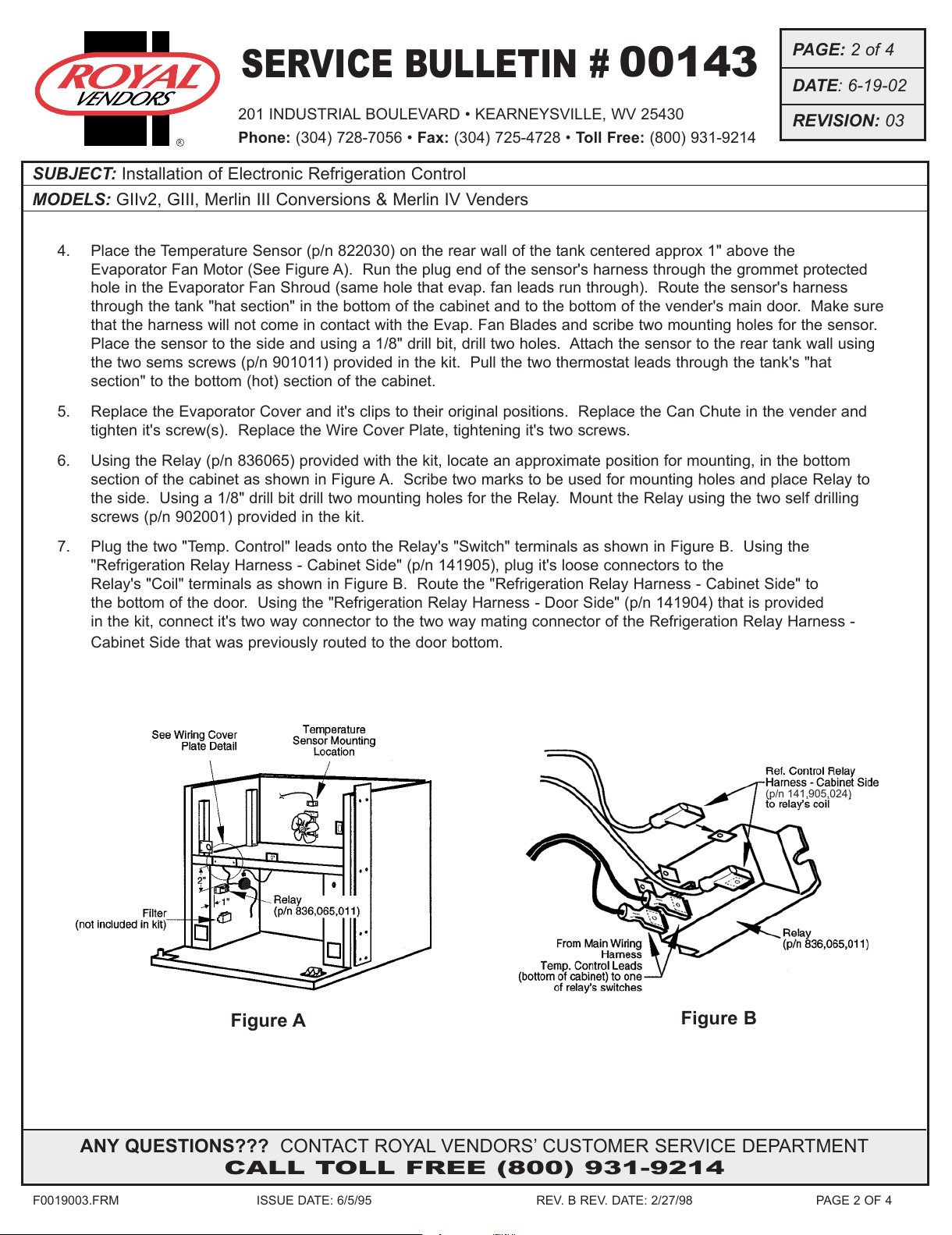
2. Remove Can Chute from vender. Loosen screws securing the Wire Cover Plate that is located in the lower, left
side of the tank area. (This part covers the wiring and refrigeration tubing that goes between the tank area and
the bottom of the cabinet via the “Hat Section”.) Remove the clips that hold the Evaporator Cover to the
Evaporator Fan Shroud Assembly and place the Evaporator Cover to the Side.
3. Optional: Remove the Thermostat from it’s mounting position by disconnecting the two terminals, removing the
two screws and backing the capillary out of it’s housing as you remove the thermostat. The thermostat will not be
needed and thus can be removed.
The following areas of this vender contain voltage, which can cause serious
injury or even death. The main power cord, supplying 110 VAC to the evapo-
rator, EMI filter, and refrigeration system. The power line from the EMI filter to
the ballast and transformer. The ballast can produce upwards of 600 volts.
Remove power from vender before working in any of these areas.
All manuals and user guides at all-guides.com
all-guides.com

201 INDUSTRIAL BOULEVARD • KEARNEYSVILLE, WV 25430
Phone: (304) 728-7056 • Fax: (304) 725-4728 • Toll Free: (800) 931-9214
PAGE: 2 of 4
DATE: 6-19-02
REVISION: 03
F0019003.FRM ISSUE DATE: 6/5/95 REV. B REV. DATE: 2/27/98 PAGE 2 OF 4
SERVICE BULLETIN #
00143
R
ANY QUESTIONS??? CONTACT ROYAL VENDORS’ CUSTOMER SERVICE DEPARTMENT
CALL TOLL FREE (800) 931-9214
SUBJECT: Installation of Electronic Refrigeration Control
MODELS: GIIv2, GIII, Merlin III Conversions & Merlin IV Venders
4. Place the Temperature Sensor (p/n 822030) on the rear wall of the tank centered approx 1" above the
Evaporator Fan Motor (See Figure A). Run the plug end of the sensor's harness through the grommet protected
hole in the Evaporator Fan Shroud (same hole that evap. fan leads run through). Route the sensor's harness
through the tank "hat section" in the bottom of the cabinet and to the bottom of the vender's main door. Make sure
that the harness will not come in contact with the Evap. Fan Blades and scribe two mounting holes for the sensor.
Place the sensor to the side and using a 1/8" drill bit, drill two holes. Attach the sensor to the rear tank wall using
the two sems screws (p/n 901011) provided in the kit. Pull the two thermostat leads through the tank's "hat
section" to the bottom (hot) section of the cabinet.
5. Replace the Evaporator Cover and it's clips to their original positions. Replace the Can Chute in the vender and
tighten it's screw(s). Replace the Wire Cover Plate, tightening it's two screws.
6. Using the Relay (p/n 836065) provided with the kit, locate an approximate position for mounting, in the bottom
section of the cabinet as shown in Figure A. Scribe two marks to be used for mounting holes and place Relay to
the side. Using a 1/8" drill bit drill two mounting holes for the Relay. Mount the Relay using the two self drilling
screws (p/n 902001) provided in the kit.
7. Plug the two "Temp. Control" leads onto the Relay's "Switch" terminals as shown in Figure B. Using the
"Refrigeration Relay Harness - Cabinet Side" (p/n 141905), plug it's loose connectors to the
Relay's "Coil" terminals as shown in Figure B. Route the "Refrigeration Relay Harness - Cabinet Side" to
the bottom of the door. Using the "Refrigeration Relay Harness - Door Side" (p/n 141904) that is provided
in the kit, connect it's two way connector to the two way mating connector of the Refrigeration Relay Harness -
Cabinet Side that was previously routed to the door bottom.
(p/n 141,905,024)
Figure A Figure B
All manuals and user guides at all-guides.com

201 INDUSTRIAL BOULEVARD • KEARNEYSVILLE, WV 25430
Phone: (304) 728-7056 • Fax: (304) 725-4728 • Toll Free: (800) 931-9214
PAGE: 3 of 4
DATE: 6-19-02
REVISION: 03
F0019003.FRM ISSUE DATE: 6/5/95 REV. B REV. DATE: 2/27/98 PAGE 3 OF 4
SERVICE BULLETIN #
00143
R
ANY QUESTIONS??? CONTACT ROYAL VENDORS’ CUSTOMER SERVICE DEPARTMENT
CALL TOLL FREE (800) 931-9214
SUBJECT: Installation of Electronic Refrigeration Control
MODELS: GIIv2, GIII, Merlin III Conversions & Merlin IV Venders
8. Remove the main Circuit Board Cover (if any). Route the Temperature Sensor from the bottom of the vender's
main door to the main Circuit Board. Plug the Temp. Sensor's connector to the proper Control Board pinout (refer
to vender wiring diagram or service manual for your vender).
9. G-III Models (804 & 660) only - Route the Refrigeration Relay Harness - Door Side from the bottom of the
vender's main door toward the main Circuit Board. Plug it's connector to the "Relay Regulator Board" (p/n
836,081,021). Using the enclosed "Harness, Regulator Board" plug attach it to the Relay Regulator Board and to
the main Control Board at the proper pinout (refer to vender wiring diagram or service manual for your vender).
Refer to Figure C for a complete layout of the refrigeration circuit.
All Other Models - Route the Refrigeration Relay Harness - Door Side from the bottom of the vender's main door to
the main Circuit Board. Plug it's connector to the main Control Board at the proper pinout (refer to vender wiring dia-
gram or service manual for your vender). Refer to Figure C for a complete layout of the refrigeration circuit.
IMPORTANT NOTE: When plugging the Refrigeration Relay Harness - Door Side to the main Control Board make
sure that you plug it to the proper connection or you could possibly damage the control board.
10. Replace main Control Board Cover (if necessary) and wire tie any loose wires if necessary. Restore power to
vender.
11. The last step is to program your vender's main Circuit Board to accept your new electronic refrigeration control
system. The features noted with checkmarks are necessary to program for correct system operation. Refer to
your service manual or vender programming instruction decal for detailed instructions of how to program your
vender's "FriG" mode for the following features.
FriG (Refrigeration) MODE
✔Cuti - compressor cut in temperature
✔Cuto - compressor cut out temperature
✔Frg - master on/off electronic control
Dsp - allow LED to display evap. air temperature
DEG - show settings in either Fahrenheit or Celsius
rELy - tests the various vender relays (heater, evap. fan, light, compressor)
All manuals and user guides at all-guides.com

201 INDUSTRIAL BOULEVARD • KEARNEYSVILLE, WV 25430
Phone: (304) 728-7056 • Fax: (304) 725-4728 • Toll Free: (800) 931-9214
PAGE: 4 of 4
DATE: 6-19-02
REVISION: 03
F0019003.FRM ISSUE DATE: 6/5/95 REV. B REV. DATE: 2/27/98 PAGE 4 OF 4
SERVICE BULLETIN #
00143
R
ANY QUESTIONS??? CONTACT ROYAL VENDORS’ CUSTOMER SERVICE DEPARTMENT
CALL TOLL FREE (800) 931-9214
SUBJECT: Installation of Electronic Refrigeration Control
MODELS: GIIv2, GIII, Merlin III Conversions & Merlin IV Venders
Main Wiring Harness
circuits for evap. fan motor and door power
eliminated for clarity
to wall outlet
Black (110 VAC)
White (neutral)
Ground
to compressor &
condenser fan
motor
Refrigeration Relay
CR1
SW1-1
SW1-2
not used
24 VDC
NEUTRAL
Control Board
Temperature Sensor
COOLING SECTION OF CABINET
CABINET
DOOR
Two way mate-n-lok
connector (bottom of door)
Relay
Regulator Board
Harness,
Regulator Board
Relay Harness - Door Side
G-III ONLY (804 & 660 MODELS)
Relay Harness - Cabinet Side
Electronic Refrigeration System
All manuals and user guides at all-guides.com
Other manuals for Merlin IV
4
This manual suits for next models
3
Table of contents