Full Gauge Digital Thermostat Kit Page 5 Rev 2.2 - March 2017
shut off voltage. A table of the resistor values for low battery protection is
included at the end of this manual.
3. Speed control: The compressor speed can be changed by adding a resistor (R1)
in series with the thermostat. If the system came with a resistor, the original
resistor value is usually the best choice and should be retained unless there is
a good reason to change it. Usually the manufacturer of the equipment has
determined the best compressor speed for the particular system to make it as
efficient as possible. Faster is not necessarily better, sometimes speeding up
the compressor results in less efficiency. A table of resistor values for various
compressor speeds is included at the end of this manual.
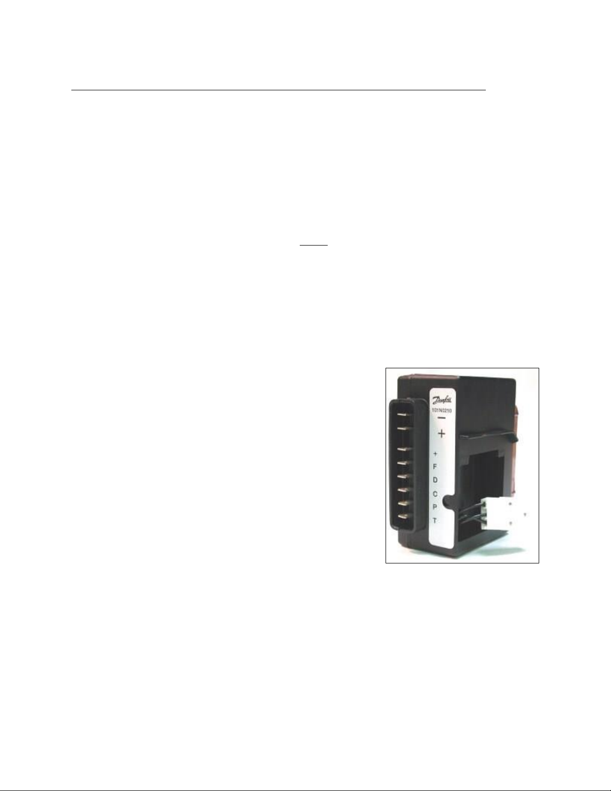
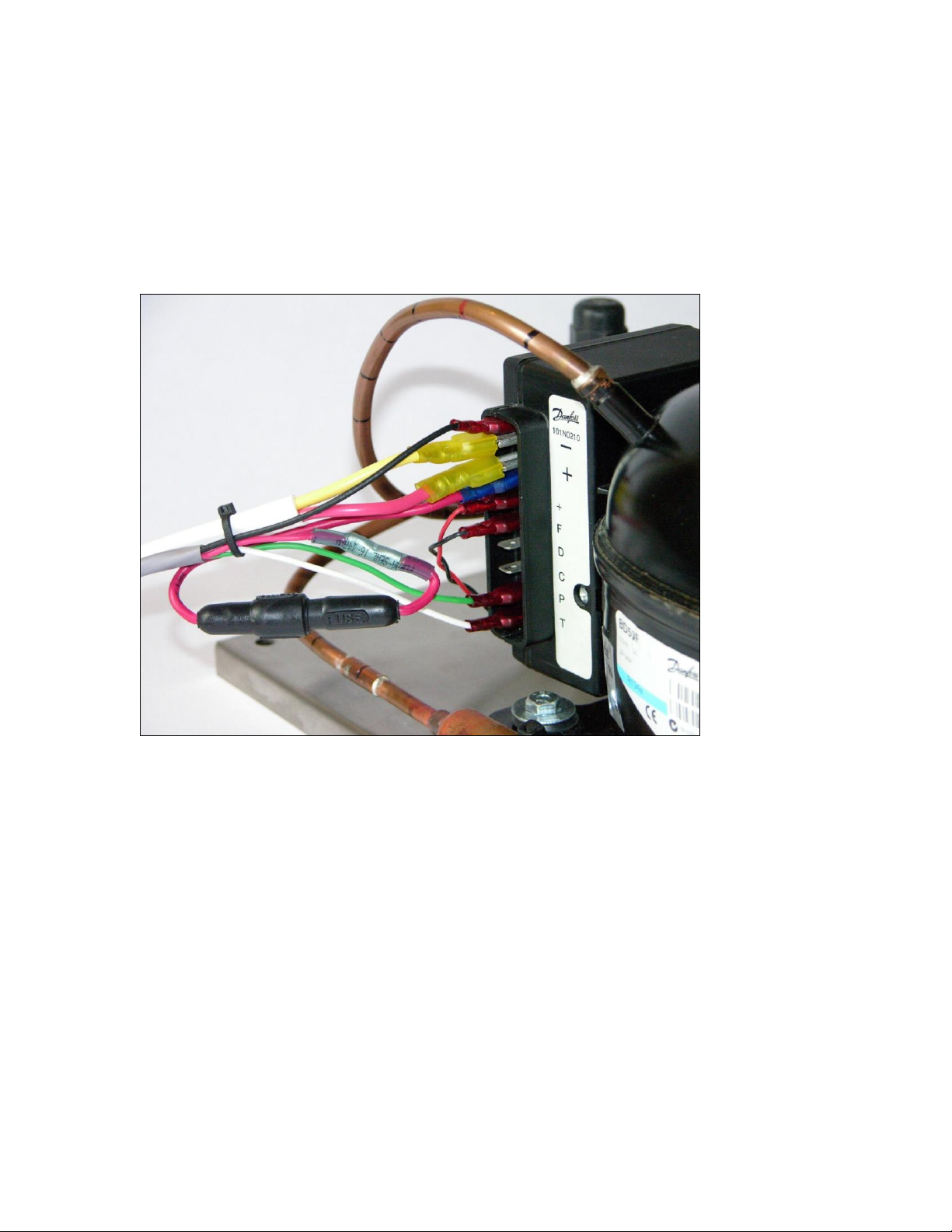
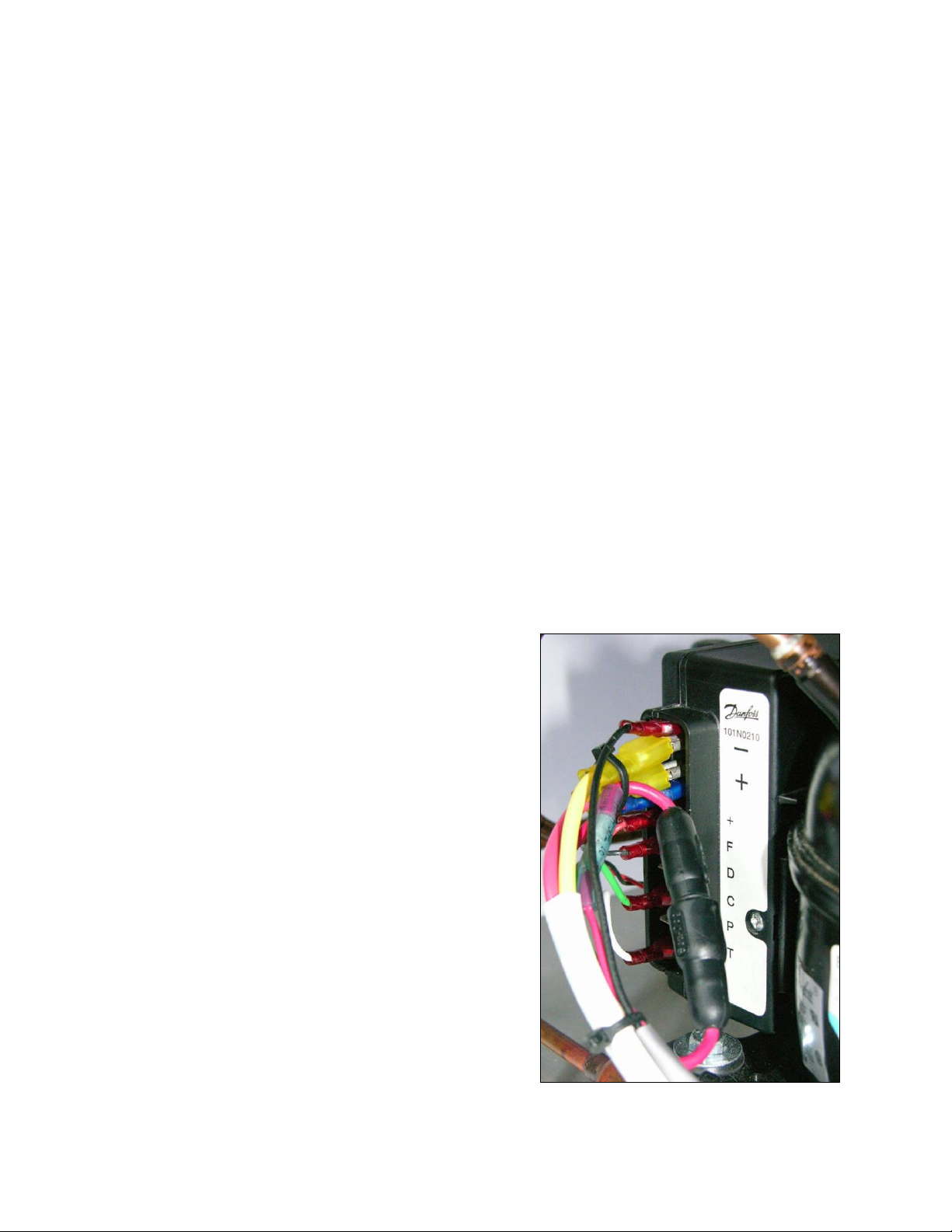
When upgrading from an analog thermostat, additional wires must be added to power
the Full Gauge thermostat from the compressor control module. The Full Gauge
thermostat power supply wire will attach to the existing power supply wires on the
large “+” and “-” terminals on the control module. Adapter terminals included in the
kit will allow the large “+” and “-” terminals to be shared. An inline fuse holder with
a 2 amp fuse will connect in series with the positive wire at the compressor module.
The power leads attach to Full Gauge thermostat connections 7 and 8. These
connections are polarity insensitive.
The thermostat wire connections on the control module will remain the same (“T” and
“C”), but the thermostat end of the wires will attach to the Full Gauge thermostat
connections 10 and 11.
The temperature-sensing probe will attach to the Full Gauge thermostat connections
3 and 4. If necessary, extend the probe wires with small gauge wire. It is best to
solder and heat shrink the wiring connections if additional length is required.
Preparation: Making Electrical Wiring Connections______
Please read the following section carefully before proceeding with the assembly and
installation of the kit.
To connect wiring to the Full Gauge digital thermostat connection terminals, strip
3/16” of the insulation from the wire ends of the multi-conductor cable before
inserting them into the appropriate wiring connection terminal. Avoid having any
loose strands of wiring that may contact other terminals and cause short circuits.
Wire ends that are attached to the wire electrical terminals will have 1/4” of insulation
stripped from the wire end before the terminal is crimped to the bare wire strands.
The wire electrical terminal also requires a second crimp to squeeze the barrel of the
terminal to the wire insulation, making a mechanical connection to relieve the strain
on the metal-to-metal crimped electrical connection.