RPS Studio RS-SB/300SLK User manual

Compact Digital
600 Watt/Second Monolite Kit
Instructions
Model RS-SB/300SLK
Check Our Website for Product Updates,
Troubleshooting, and Instructions
http://dotlinecorp.com

Flash Output
Power Guide Number f/Stop at 10 ft*
Using reflector
Full Power Guide Number 220 f/22
Without reflector
Full Power Guide Number 160 f/16
*Assuming ISO 100 Sensitivity
Technical Data
Maximum Output Power 300 Watt/Seconds
Maximum Guide Number 220 (ISO 100/ft)
100% Recycling Time 1-3 seconds
Power Adjustment 1/32th to Full Power
adjustable 1/10th stop
Modeling Lamp 110-120V 75 Watts
— On/Off Switch
— Tracking
Color Temperature Daylight 5600-5800° Kelvin
Triggering Methods - Synch Cord
- Test Button
- Internal Photo Cell
Triggering Voltage 5V DC
Synch Distance up to 36 ft
Voltage Range 110-120 V AC
Flash Tube User Replaceable *
Reflector/Softbox Mount 3-3/4" diameter mount
Weight 2.8 lbs
- Page 2 -
* Note: This unit uses a “U” shaped tube. Even with the unit un-
plugged the unit maintains considerable power in the internal
capacitor. We recommend having a qualified service agent
change the flash tube.

- Page 3 -
• Caution •
• Even unplugged, the unit maintains considerable internal
voltage. There are no user serviceable parts inside. Do not
disassemble! Refer to authorized service center for any
repairs.
• Do not exceed 75 Watt modeling lamp. The excess heat
can damage the unit.
• Do not touch the bulb when it is hot!
• When not in use, disconnect from the power supply
• Avoid sudden impacts as this can damage the flash tube
and/or modeling lamp!
• The unit must be connected to a 3 prong grounded outlet.
Preparing Your Flash for
Use
These units can be used with
or without the supplied
reflector. Use the reflector to
gain higher, more focused
direct light output. Remove the
reflector when using the unit with umbrellas or softboxes.
Mount the monolite on the post of the supplied light stand
and securely tighten the locking knob. Make sure the flash
tube and modeling light are seated correctly. Be sure the
power switch ("1/0") is OFF ("0") and then plug the power
cord into the unit first, and then the wall outlet. NOTE: This
unit is designed to work on 110-120 Volts 60 HZ AC current.
Once the unit powers up you will hear a “beep” and the
green light to the left of the test button will glow. The digital
display will show the current power settings.

- Page 4 -
Setting the Flash Unit’s Controls
Photo Cell This cell senses the light of another flash unit.
Digital Display Shows power output. Range 6.0 (Full
Power) to 1.0 in full stop (and 1/10 stop) increments
Beeper On/Off Press to turn audible ready beeper off.
Press again to turn on. Beeper light indicates status.
Modeling Light Mode Press this button to turn the
modeling lamp on/off. When on, the lower LED to the right of
the button lights and the modeling light will “track.” To adjust
the power ratio on the modeling light independently of the
flash, push the modeling lamp power up or down. The
display will blink indicating modeling lamp power setting.
Photocell
Digital Display
Beeper On/Off
Modeling
Light
Mode
Modeling
Lamp
Power
Sync
Cord
Power Cord
Tilt Knob
Remote
Display
Remote
Button
Ready LED
Test
Button
Flash
Power
Power On/Off
Fuse Cover
Umbrella Mount
Mount Knob

Setting the Flash Unit’s Controls (continued)
3.5mm Synch Cord Input A synch cord is provided with
your flash unit. The input is a 3.5mm mini plug.
Power Cord Input 110v AC Power Cord input. Use a
grounded outlet.
Tilt Knob Loosen this knob to tilt (bounce) the entire flash
head.
Remote Button/Remote Display Indicates the status of
the built-in photocell. Push the remote button to change the
status. Push the button to change the settings.
LED Off: Built-in photocell sensor is off.
LED 1 Lit: Photocell is ON and the unit will flash when
another flash unit fires.
LED 2 Lit: Flash unit will fire on 2nd flash (after preflash).
LED 3 Lit: Flash unit will fire on 3rd flash
LED 4 Lit: Flash unit will fire on 4th flash
LED 5 Lit: Flash unit will fire on 5th flash
Ready LED Indicates the flash is ready to fire when lit.
Test To fire the flash without taking a picture, push the Test
button.
Flash Power Use the Up/Down arrows to control the power
output of the flash. Adjustable in 1/10th f/stop increments.
Power On/Off Main switch controls power 1 = On, 0 = OFF
Fuse Cover Remove power cord, and lift the door to
replace fuse. 2 Additional fuses are supplied.
Umbrella Mount Slide the umbrella shaft into this opening
Mount Knob Tightens monolite onto a 5/8" post.
- Page 5 -

- Page 6 -
Using the Kit’s Other Components
Light Stands The light stands are easily adjustable. Simply
extend the base legs to the maximum spread and tighten. Then
adjust the height by pulling the sections to the desired height and
locking the knobs in position. Mount the flash unit on the 5/8"
post and tighten.
Umbrella A soft, wide angle light can
be obtained using the supplied
umbrella. Extend the umbrella, and
then insert the umbrella shaft into the
round umbrella mount on the head.
When using the umbrella, remove the
reflector.
Softbox This kit is supplied with a
softbox. Unlike an umbrella, which reflects light back at the
subject, a softbox softens the light pointed directly at the subject.
This is especially useful for portraits.
Assembling the Softbox
This is easiest when the flash head is
mounted on the light stand.
Remove the reflector, and place the
softbox around the flash unit. The silver
side should be inside, and the black side
outside. Let it fall.
Mount the softbox adapter ring onto
the front of the flash unit as shown.
At this point it is easiest to point the
unit towards the ceiling.

Assembling the softbox (Continued)
Insert the rods supplied into the holes
on the bracket. These rods will bend to
form the shape of the softbox. See
picture.
Now bend each rod and insert into the
silver cups sewn into the front diffusion
panel as shown in the picture.
At this point you can lift the softbox
and then attach the front edges of the
softbox to the front edges of the
diffusion panel using the hook and
loop. Be sure you match the 20 inch
side and the 28 inch side to the
appropriate side of the front diffusion
panel.
Gently cover the back of the strobe with
the material and tighten the draw string.
Internal diffuser.
If you would like to use the internal diffuser, gently open one side
of the soft box and locate the hook and loop tabs built into the
side of the softbox. Attache the tabs on the internal diffuser to
these tabs. This will provide a softer, more even illumination.
The softbox is best used when placed above the subject shooting
down at an angle; however, experimentation and your own
creative ideas really come into play.
- Page 7 -

1 Year Limited Warranty.
Dot Line Corp. warrants that if the accompanying product proves to be
defective to the original purchaser in material or workmanship within 1
year from the original retail purchase, Dot Line Corp. will, at its option,
either repair or replace same without charge (but no cash refund will be
made).
What you must do to enforce the warranty: You must deliver, mail or
ship the product together with the original bill of sale, to:
Dot Line Corp. 9420 Eton Ave., Chatsworth, CA 91311
Phone 1-800-423-2624 Fax 818-700-9797.
Limitation of Liability and Remedies: This warranty is void if any
defects are caused by abuse, misuse, negligence or unauthorized
repairs. All liability for incidental or consequential damages is specifically
excluded. The company shall have no liability for any damages due to
lost profits, loss of use or anticipated benefits, or other incidental,
consequential, special or punitive damages arising from the use of, or
inability to use, this product, whether arising out of contract, negligence,
tort, or under any warranty, even if the company has been advised of the
possibility of such damages. The Company’s liability for damages in no
event shall exceed the amount paid for the product. The Company
neither assumes nor authorizes anyone to assume for it any other
liabilities.
Some states do not allow for the exclusion of incidental or consequential
damages, so the above exclusion may not apply to you. This warranty
gives you specific legal rights and you may have other rights which vary
from state to state.
RPS Studio Products are Marketed exclusively by:
Dot Line Corp. 9420 Eton Ave.
Chatsworth, CA 91311
818-700-9997 • Fax 818-700-9797
www.dotlinecorp.com
email: [email protected]
Product Made in China © Dot Line Corp. 2008
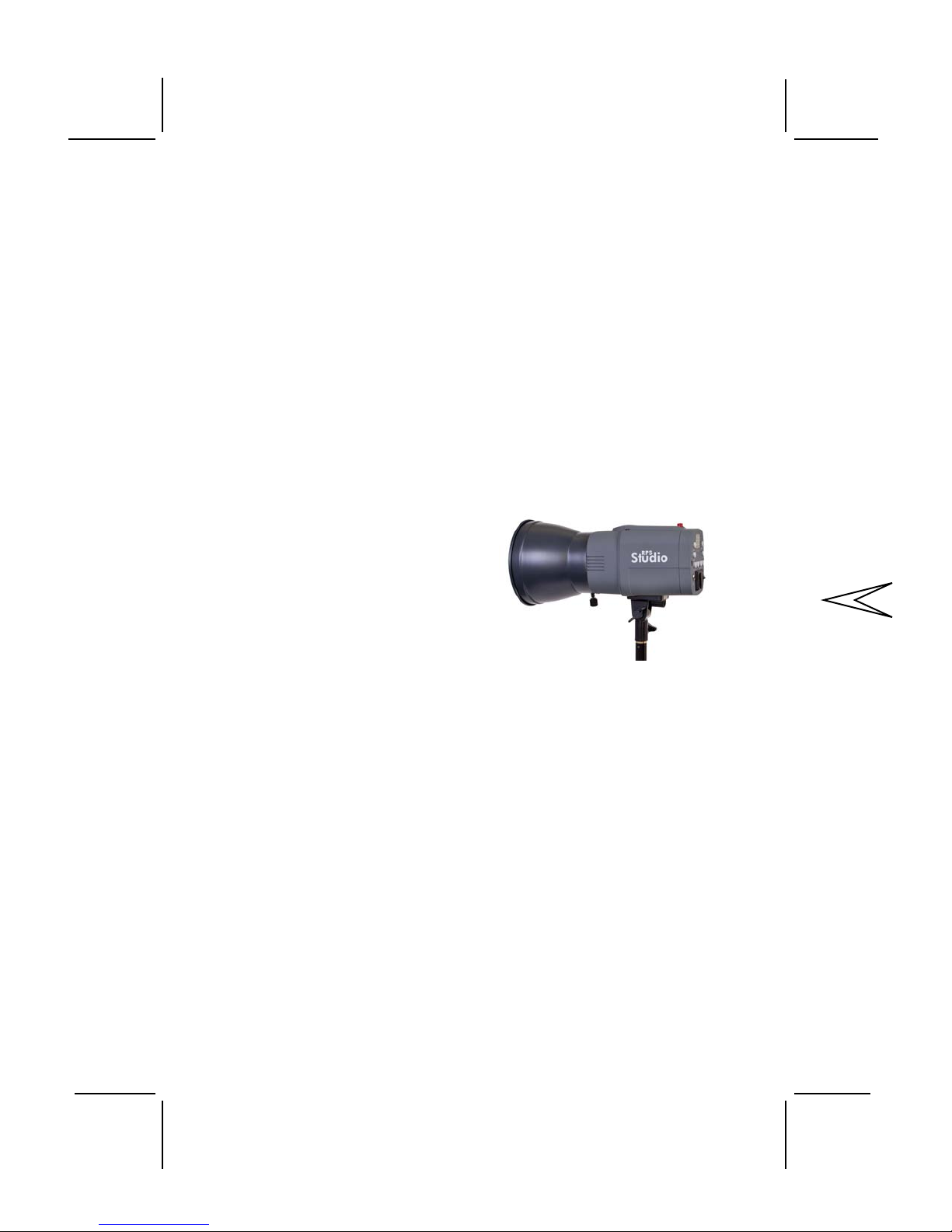
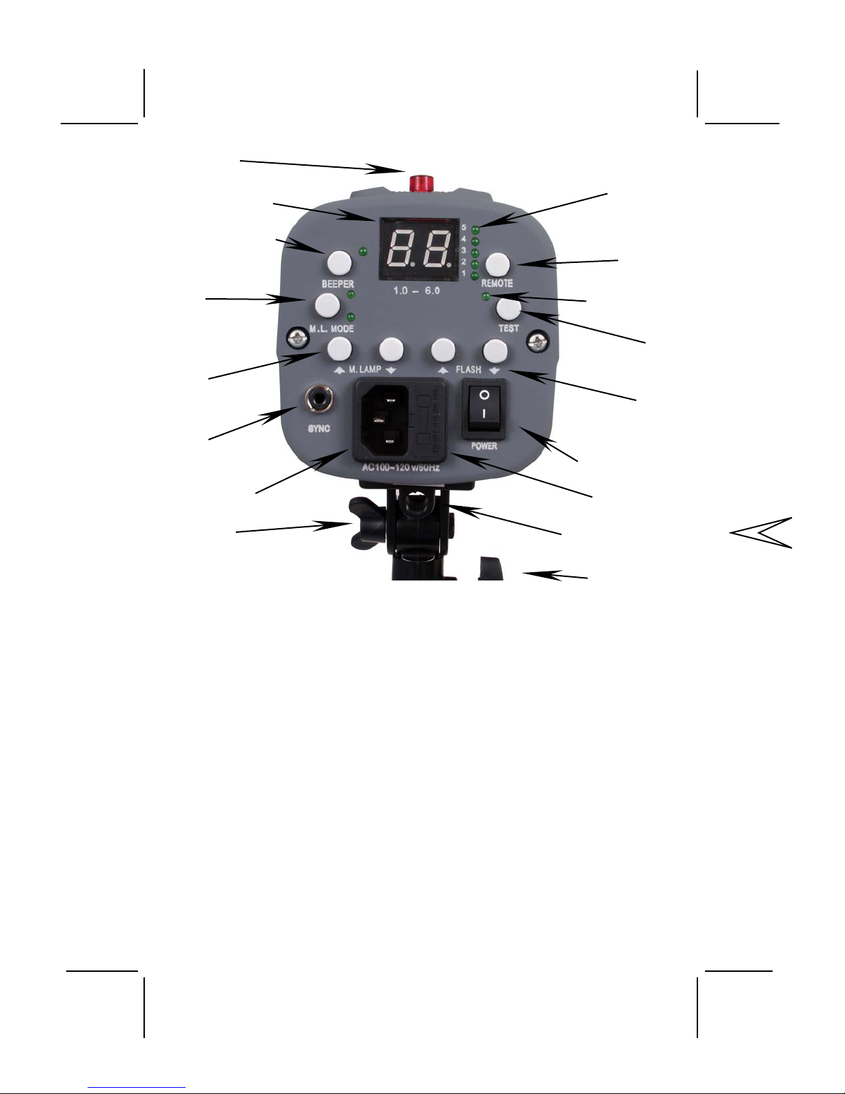
These Instructions are for RS-SB/300 monolites. Pictures may vary.
Specifications are subject to change. Printed March 2009.
Table of contents
Other RPS Studio Lighting Equipment manuals