RSI MasterBath User manual

Page 1
33 1
/
2
"
81"
Figure 1
Tack in shims at
low points.
Mark the outlines of
all cabinet sizes on
the wall to check the
actual cabinet
dimensions against
your layout.
Strike level baseline from highest
point of floor.
UNEVEN FLOORS AND WALLS
Because floors and walls have uneven spots which will affect the
installation, it will be necessary to locate these uneven areas. Wall
and floor unevenness can cause cabinets to be misaligned result-
ing in “racking” or misalignment of the doors and drawer fronts.
Uneven spots can be found with a straight edge or a 4’ level.
Simply run the straight edge along the floor and wall to identify
any uneven areas. Where these uneven spots interfere, high spots
can be removed by scraping or sanding the excess plaster. Low
spots can be shimmed.
LOCATE STUDS
Locate the wall studs with a stud finder or tap on the wall to locate
a “solid sound.” This generally will tell you where the wall studs are
located. You can verify this location by driving a small finishing nail
into the wall. Make sure this is an area that will be covered by the
base cabinets. Mark a chalk line at the center of the wall studs at
the top and bottom of the cabinet position. Normally the wall studs
are located 16” apart, center to center.
CABINET HEIGHT
To establish the height of your base cabinets,measure up and mark
the wall at 331⁄2” from the highest spot on the floor. Use this mark
as a starting point and draw the lines around the bathroom. Mark
the outlines of all cabinets on the wall to check actual cabinet
dimensions against your layout (Figure 1).
HARDWARE
Decorative and installation hardware such as nails, screws, glue,
tape, etc. are not included.
R37077
Rev. 11-11
Step 1. Preparation
MasterBath & MasterBath Elite
Please read prior to installation

Page 2
Before beginning the cabinet installation, you will need to
apply the finished overlays to the side (s) of the cabinet or run of
cabinets that will be exposed to the room. Just follow the below
simple steps to apply the flush fit end panels.
Materials:
Finished Flush Fit End Panel, Roll of Double Sided Tape
(Suggest 1 roll per flush fit end panel) or construction
adhesive. (Neither are provided.)
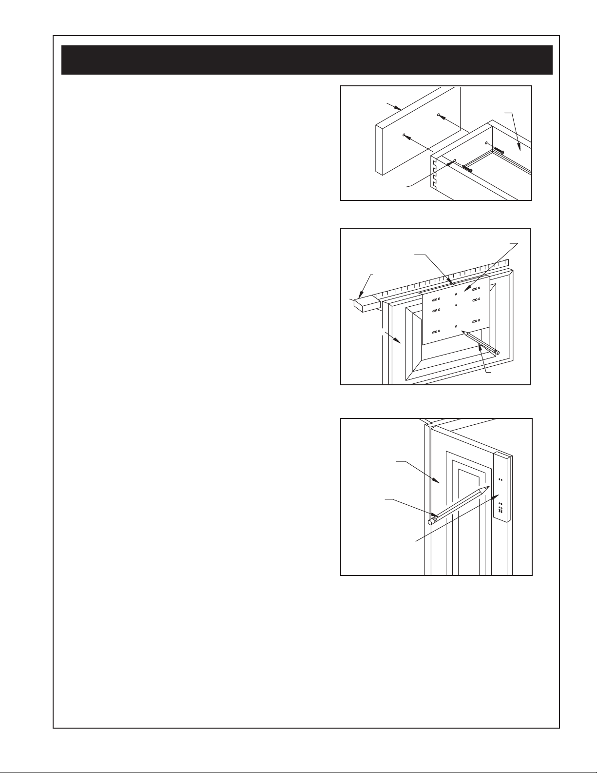
Toe Notch Instructions
Note: If flush fit end panel is on the left side of cabinet, the toe
notch will be on the right side of the flush fit end panel. If the flush
fit end panel is for the right side of the cabinet, the toe notch will
be on the left side of the flush fit end panel.
Toe notch out the flush fit end panel.
a) Line up the bottom of toe notch with the bottom of
the overlay
b) Using a pencil draw a line along the edge of the
toe notch
c) Using a jigsaw or hand saw, cut along the line.
Make sure the saw blade is inside the toe notch
area, which will be removed.
d) Any left over pencil marks can be erased with a
pencil eraser.
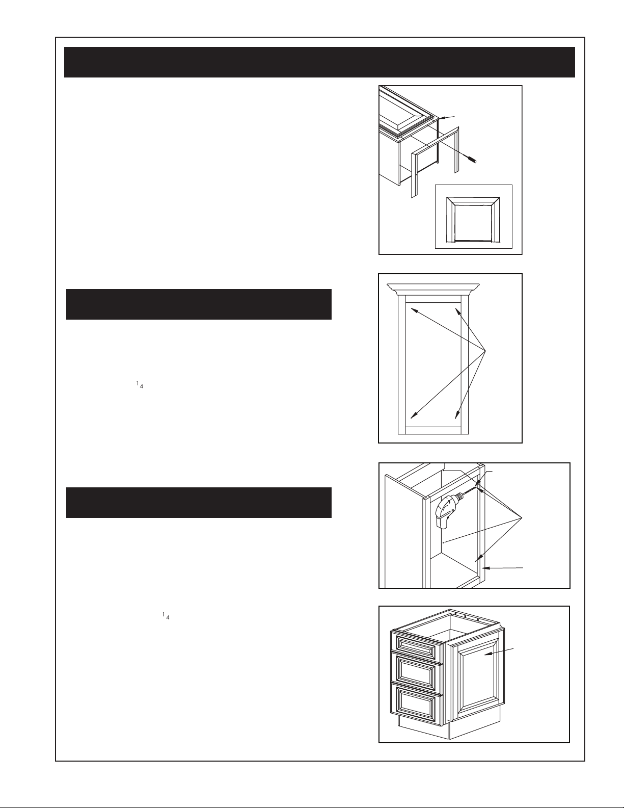
1. Cut and apply double sided tape to flush fit end panel or
use construction adhesive (Figure 2). If using construction
adhesive, use tape guidelines as glue guideline and then
move to Step #2.
a) Cut the roll of double sided tape into strips. Cut
tape strips to the lengths and quantities listed on the
tape template. You will need approximately one
roll of tape for each flush fit end panel.
b) Apply the tape to the flush fit end panel following
the tape template diagram. Tape strips applied
along the edges of the flush fit end panel should be
1/4” from the edge.
c) As you apply each tape strip, run your finger along
the strip, applying pressure to make sure the tape
makes complete contact with the flush fit end panel.
2. Apply flush fit end panel to cabinet side panel
a) Remove the backer from each tape strip.
b) Holding the flush fit end panel at an angle from the
cabinet side panel, slide the front edge of the flush
fit end panel into the face frame groove. Make sure
the entire edge of the flush fit end panel is seated
inside the face frame groove.
c) Align the top of the flush fit end panel with the top
of the cabinet side panel and press the flush fit end
panel against the side panel.
d) Working from front to back, apply pressure along
the entire surface of the flush fit end panel to make
sure each tape/adhesive strip makes complete
contact with the cabinet side panel.
e) Allow the tape/adhesive to cure for 1 hour before
proceeding with the cabinet installation.
Step 2. Flush Fit End Panel Application Instructions
NOTE: TAPE/ADHESIVE SHOULD BE APPLIED 1/4” FROM EDGES OF FLUSH FIT END PANEL.
Strip/
Adhesive
LEFT
SIDE
RIGHT
SIDE
Strip/
Adhesive
Strip/
Adhesive
Strip/
Adhesive
Strip/
Adhesive
Strip/
Adhesive
Strip/Adhesive
Strip/Adhesive
Strip/Adhesive
Strip/Adhesive
Figure 2

Page 3
Step 3. Cabinet Installation
INSTALL HUTCH OR LINEN CROWN MOLDING (if necessary)
Crown molding,sold separately,can be installed on the Hutch or Linen cabinet. The length of crown molding pieces will need to be cut
from the full length piece. You will need to miter the pieces to fit the Hutch or Linen. Please see Figures 3 and 4 on how to install the crown
molding to the cabinet. If your Hutch or Linen will be installed with a side against a wall it is not necessary to attach molding to the side
against the wall. Cut to fit your wall (Figure 5).
Figure 3
ATTACH FRONT MOLDING
Front molding
NOTE: Make sure to align molding
with face frame.
TOP VIEW
Figure 4
ATTACH RIGHT AND LEFT
SIDE MOLDINGS
Front molding
Use either white glue or
carpenter’s glue (not provided)
Use 7/8" screw (not provided)
Left side molding
Right side molding
TOP VIEW
NOTE: Make sure to align side
moldings with front molding.
Wall
Unused side molding
(cut to length)
Figure 5
FRONT VIEW
Cabinet
Wall
Figure 6
UPPER UNIT
BASE
UNIT
Brackets Brackets
Bottom panel
FACE FRAME MENDING DETAIL
Figure 7
Upper face frame
Lower face frame
SIDE PANEL MENDING DETAIL
Upper side panel
Lower side panel
2-PIECE LINEN ASSEMBLY
The 15” Linen,18” Linen with Drawers and 18” Linen with Doors
are 2-piece units that require assembly prior to installation. Place
the upper linen unit on top of the lower linen unit. The upper unit
has six attachment brackets in place at the bottom, interior of the
unit (Figure 6).
If you purchased a linen with drawers, you need to remove the
drawers to have access to the attachment brackets on the upper unit.
Reach through the back or front of the bottom unit to remove one
screw on each attachment bracket so the bracket hangs down ver-
tically (Figure 7). Align the upper and lower units, first making sure
the front of the linens (face frame) line up, then the sides. (The over-
all width of one unit may be slightly larger than the other unit. This is
normal and does not
compromise the function-
ality or structural integrity
of the units.) Once the
top and bottom units are
aligned, secure the two
together by screwing the
front two brackets to the
face frame of the lower
unit first. Then repeat
process for each side
panel. Attaching the two
front attachment brackets
first and then the brack-
ets on each side last will
create proper alignments.

Page 4
LINEN INSTALLATION
Hardware for installation not included. To fasten the linen to the
wall, drill pilot holes at the stud location through the top back rail,
then fasten with #8 x 2” screws. If the linen sits in between the
studs,you will need to use toggle bolts to fasten to the wall. It is
not recommended to place the linen in a corner where the back
is not against a wall.
NOTE: A 3” Linen Filler must be used if one side of the linen is
placed next to a wall. This will prevent doors and drawers from
rubbing.
The linen comes with two side molding pieces to install over the
seam line between the upper and lower units. If a side of the linen
is against a wall or cabinet DO NOT install these pieces on that
side. If a side of the linen IS NOT against a wall or cabinet, use
finishing nails (not provided) to nail the side molding over the seam
line. Three to four finishing nails per side should be sufficient. Use
the color stick provided in the parts bag to color over the top of
the finishing nails to hide the nail heads. Install one side molding
piece per side.
INSTALL BASE CABINETS
NOTE: Fillers must be used when a drawer bank or vanity is next
to a wall. Minimum of 1/4” or drawers will rub.
When starting the installation process, it is very important to start
your installation from a corner wall and work out. If the wall is not
straight, you may need to use a filler and scribe it to the wall’s
shape (Figure 8). Fillers may also be used to accommodate wall
to wall installations where the cabinets do not fit exactly.
Once you have identified the starting point, take the first cabinet
and shim it to the previously established level line. Drill pilot holes
at the stud location, through the back rail and into the studs. Then
securely fasten the cabinet to the wall,using #8 x 21⁄2” screws
and appropriate anchors (Do Not Nail). Make sure the cabinet
remains square and level after wall attachment.
ATTACH CABINETS TOGETHER
Once you have securely fastened the starting cabinet to the wall,
line up the front of the cabinets and use “C” clamps to simply join
the next cabinet to it. Place the “C” clamps on the adjoining stiles
and carefully clamp the two together. Carefully line up the top and
shim the bottom of the cabinets. Now drill a pilot hole,using a 1⁄8”
drill bit, through the adjoining stiles. Once done, draw the two
together, use two #8 x 21⁄2” wood screws (Figure 9).
NOTE: When securing a 24” curved base cabinet to another
cabinet,use two #8 x 21⁄2” woodscrews (Figure 10).
Installation Tip: Use a little wax on the screws to help seat them
into the wood.
Continue installing the remaining base cabinets in the same
manner. After joining all of your base cabinets together, verify all
cabinets are level and secure each cabinet to the wall.
Figure 8
TOP VIEW
Wall Block
Cabinet
Filler
Wall
3" filler
Trim to
desired size
and shape.
Filler
Wall
Shim
Shim
Figure 9
Installation
spacer
Stiles
Scrap block
1/8" diameter
2 #8 x 2 1/2" screws
Curved cabinet
Figure 10

Page 5
Figure 13
24"
Step 4. Specialized Cabinet Installations
Figure 15
Wall
Back splash Counter top
KNEE DRAWER
Your knee drawer can be installed by either mounting it to the
sides of the adjacent cabinets or directly to the underside of your
countertop.
A. COUNTERTOP INSTALLATION (recommended)
Start the knee drawer installation by using the screws provided to
connect the angle brackets to the drawer glides (Figure 11),then in-
stall the knee drawer to the underside of the counter top (Figure12).
B. CABINET TO CABINET INSTALLATION
Ensure that cabinets are approximately spaced at 24”. (Figure 13)
Attach to cabinet side with the #4 x 3⁄4” screws and plastic spacers
as shown. (Figure 14)
HUTCH
Install the hutch after you have completed installing all of the base
cabinets and the counter top. Set the hutch on top of the counter
top. Fasten the hutch by drilling pilot holes at the stud location
through the back rail. Then fasten the hutch to the wall with #8 x 2”
screws. If the hutch sits in between the studs, you will need to use
toggle bolts to fasten the hutch to the wall. For water protection it is
recommended that you caulk the hutch to the countertop or to install
a side splash around the bottom edge of the hutch (Figure 15).
LINEN
Your 15” or 18” Linen can be installed as
part of a cabinet run, or as a standalone
unit. In either case, fasten the linen by drill-
ing pilot holes at the stud location through
the back rail. Then fasten to the wall with
#8 x 2” screws. If your linen sits in between
the studs, you will need to use toggle bolts
to fasten to the wall. If your linen is used in
a corner where the back is not against a
wall, secure your unit with furniture restraint
hardware, such as wall anchor rings and
cable restraints. This will prevent the linen
from toppling over.
Figure 11
Figure 14
Figure 12

Page 6
Step 5. Changing the Door Swing
180
o
180
o
Figure 16
Face
frame
Figure 17
3/32" diameter drill bit
Face frame
Figure 18
Loosen screw for
adjustment of door
up and down
Loosen screw for
adjustment of door
left from right
Figure 19
Push glides outward
Glides
Because some installations require a cabinet door to open in the op-
posite direction, it may be necessary to switch the hinges from one
side of the cabinet to the other. You must first remove the door by un-
screwing the hinges from the face frame. Then using a 3⁄32” diameter
drill bit, drill holes 3⁄4” deep on the other side of the face frame. Rotate
the door 180 degrees and screw the hinge onto the opposite side of
the face frame (Figures 16 and 17).
Step 6. Hinge Adjustment
It usually is necessary to adjust your hinges once you have finished
the installation of your cabinets (Figure 18).
Step 7. Drawer Adjustment
DRAWER GLIDES – MASTERBATH
To adjust the alignment of the glides you must first remove the
drawer from the cabinet. Push both glides outward toward the
sides of the cabinet until they stop (Figure 19). Set the drawer
back in the glide tracks and push the drawer all the way into the
cabinet. The glides will align automatically when the drawer box
is pushed back in. Slide drawer back 5-6 times to self adjust.
DRAWER GLIDES – MASTERBATH ELITE
To remove the drawer from the cabinet,extend the drawer to the
outer most location. Then reach underneath the drawer to the at-
taching clips located at the front of the drawer box. Then squeeze
the clips pulling toward you which will release the glides from the
drawer box. The drawer will now be ready to be removed. Lift the
drawer away. To reinstall the drawer, make sure glides are pushed
in all the way into the cabinet. Set the drawer back in the glide
tracks and push the drawer all the way into the cabinet. When the
clips attach to the glide you will hear a click. The glides will align
automatically when the drawer is pushed back in.
DRAWER FRONT
Make all drawer front adjustments prior to installing handle hard-
ware. Drawer fronts can be adjusted by simply loosening the
screws that are screwed into the back, and adjusting the drawer
fronts accordingly. The holes are oversized on the drawer box to
allow for perfect drawer front alignment (Figure 20).

Page 7
Step 8. Drill for Hardware
Drawer front
Drawer box
Oversized holes
Figure 20
Figure 21
Drawer hardware placement guide
Center mark
Tape measure
Drawer front
Pencil
Figure 22
Pencil
Cabinet door
Door hardware
placement guide
(Hardware sold separately)
DRAWER FRONT HARDWARE
PLACEMENT
Hardware Placement Guide provided
Measure the exact width and determine the center point of the
drawer front. Align the drawer hardware placement guide directly
over the center point of the drawer front. For a knob,mark the cen-
ter point. For a handle,mark the outside points that correspond to
the exact width of the desired handle hardware. Drill from the out-
side of the drawer to the inside. A 3/16” drill bit is recommended
to allow for final adjustments for exact alignment (Figure 21).
DOOR HARDWARE PLACEMENT
Hardware Placement Guide provided
Place the handle hardware guide on the corner of the cabinet
door where you would like to have your handle located. Mark
the point on your door that corresponds to the size of your handle
hardware and your door finish. Please note that you must use the
outside holes for the Satin White door finish. Drill through your
marks from the outside of the door to the inside. A 3/16” drill bit
is recommended to allow for final adjustments to exact alignment
(Figure 22).
Every effort was made to provide you with an accurate template,
but we cannot be held responsible for the final print quality.
Always do a visual check prior to actual drilling.

Page 8
9. Standard Fillers /Decorative Fillers
Figure 23
Face frame
Side panel
Shim
(not provided)
Rope/column filler
Figure 24
Face frame
Side panel
Curved front face
Rope/column filler
Shim
(not provided)
Figure 25
Finishing nail
Toe kick
Decorative Fillers: In contrast to standard fillers, which are trimmed for a
proper fit to complete a cabinet run, decorative fillers require a 3” spac-
ing between cabinets.
STANDARD CABINET INSTALLATION
• Spacecabinets3”apart.
• Clampllerandanynecessaryshimsinplacejustbehindcabinetface
frame (Figure 23).
• Pre-drillholesthroughcabinetsideataposition3/8”behindface
frame (two holes on right side and two holes on left side). Use a 3⁄16”
drill bit.
• Securellerinplacewith#6x15⁄8” screws.
• Removeclamps.
CURVED FRONT CABINET
• Spacecabinets3”apart.
• Clampllerandanynecessaryshimsinplace.Shimtobeusedon
cabinet adjacent to curved cabinet (Figure 24).
• Followremaininginstructionunder“CabinetInstallation”above.
Step 10. Toe Kick Installation
The toe kick should be attached once all of your cabinets have been
installed and secured to the wall. Cut the toe kick to your exact dimen-
sions. Use small finishing nails to attach the toe kick to your cabinets. It is
recommended that a bead of high quality caulking material be used to
seal the toe kick to the floor (Figure 25).Use touch up fill stick (provided)
on any exposed edges of the toe kick.

Page 9
11. Bath Storage Topper/Wall Hutches
Figure 26
TOP VIEW
Face frame
Use 3/4" screw
(not included)
Suggested
hole
locations
Figure 27
3/16" diameter drill bit
Pilot holes
Figure 28
Face frame
Side panel
End panel
Figure 29
For your convenience, matching crown molding has been included
with your Bath Storage Topper or Wall Hutch.
To install, simply set the molding on top of the cabinet. Make sure the
molding is aligned side to side on the face frame. Additionally, make
sure the front, bottom edge of the crown molding lines up with the outer
edge of the door. Mark pre-boring locations on face frame with a pen-
cil. Drill into face frame with a 3/16” drill bit. Screw crown to cabinet
using #6 x 3/4” wood screws (not included) (Figure 26).
• Tohangcabinet,itwillrstbenecessarytolocatethestudsinthe
wall (in some cases where a stud location will not work, it will be
necessary to use a Hollow Wall Anchor).
• Afterlocatingthestuds,youwillneedtopre-drillholesthroughthe
back panel.
• Placethecabinetintoplace,and using a #8x2”woodscrew,
secure the cabinet to the wall (Figure 27).
Step 12. Decorative End Panel
• DecorativeEndPanelisinstalledovertheushFitEndPanels.See
Step 2.
• Removethecabinetdoor.Thisallowsaccesstoclamptheendpanel.
• Pre-drilleightholesaroundperimeter(1”fromedge)ofcabinetside
panel from the inside (Figure 28).
• Measuredown1⁄4” from the top of the cabinet. Make a pencil mark.
Align top edge of end panel with pencil mark and secure to cabinet
with clamps.
• Securetheendpaneltothecabinetusing#6x1”woodscrews
(Figure 29).
CAUTION: Never secure decorative end panel by inserting screws into
center of the panel.
Step13. Mirrors
Determine where to hang the mirror. Using the mirror clips on the mirror,
measure the correct spacing and mark on to the wall. Determine if studs
are located at the marks. Hollow wall anchors will need to be used
if no studs are located in the desired hanging location. You may also
use hanging wire to hang the mirror from a single stud or wall anchor.
Hardware must be capable of supporting 75 lbs. (34 kg) minimum.
• Drivescrewsintostudsorwallanchors,makingsurethescrewsare
level. Use at least a 1 1⁄4” wood screw.
• Clipmirrorontoscrewheads.

Page 10
Step 14. Furniture Rail
Face frame
Figure 30
Pilot holes
Side panel
3/16" diameter drill bit
Figure 31
1/8" toe kick
Parts List
Strike Plate 1
1hctaLhsuP
Push Latch Screw 2
Shelf Support 12
Adjustable Shelves 3
Hinge Bushing 2
2 + 2e & Hinge PlategniHtoviP
Mirror 1
Qty
Before installing the Furniture Rail you will need to install the stan-
dard 1⁄8” finish toe kick.
• Fitupfurniturerailtocabinets.Iftrimmingofthefurniturerailis
required, do not trim off one end. Cut the desired length out of
the center of the furniture rail and rejoin. This will preserve the
edge detail.
• Clampthefurniturerailintoplace.
• Measure1”fromfrontofcabinetbottompanel.Pre-drillintothe
furniture rail with a 3⁄16” drill bit. Be careful NOT to drill too far
into the furniture rail (Figure 30).
• Securefurniturerailintoplacewith#6x1”woodscrews.
• Removeclamps.
Step 15. Toe Kicks
Before installing a Decorative Toe Kick, you will need to install the
standard 1⁄8” finish toe kick.
When installing the decorative toe kicks (straight or curved) it will
be necessary to remove the doors or drawers from the sink base
cabinets or drawer banks (the decorative toe kick is designed to fit
under the sink base or drawer bank in the cabinet run).
• Oncethedoorsareremoved,clampthetoekickintoplace.
• Measurein1”fromthefrontedgeofthebasecabinetoor(or
just behind the face frame).
• Usinga3⁄16” drill bit, pre-drill three holes.
• Using #6 x 1” wood screws, secure the toe kick into place
(Figure 31).
Step 16. Surface Mount
Medicine Cabinet
IMPORTANT: Before beginning assembly, carefully remove all
parts from carton. Make sure you have all the parts listed below.
To make assembly easier, please review the assembly instructions
prior to assembly.
1. ATTACH CROWN MOLDING TO CABINET.
For your convenience, matching crown molding has
been included with your Medicine Cabinet. Determine
location of hinge holes for left or right swing before you
install crown. (Figure 32).
• Setthemoldingontopofthecabinet.Makesurethe
molding is aligned side to side on the face frame.
Additionally, make sure the front, bottom edge of the
crown molding lines up with the outer edge of the
face frame.
• Markpre-boringlocationsonfaceframewithapencil.
• Drillintofaceframewitha3⁄16” drill bit.
• Screw crown to cabinet using #6 x 3⁄4” wood
screws (not included). Refer back to Figure 26 of
Step 11 for diagram.

Page 11
2. ATTACH CABINET TO WALL.
The most secure way to hang this cabinet is by using
four screws (not included) – two through upper and two
through lower section of back panel into wall stud. If it is
not possible to fasten to wall stud, we recommend using
3/16” toggle bolts or appropriate wall anchor. Hard-
ware must be capable of supporting 75 lbs.(34.13 kg)
minimum.
• Mark the location(s) of the wall studs (if available)
on the inside of the cabinet and drill two 3/16”
holes through the hanging rail and two 3/16” holes
through the cabinet back (Figure 33).
• Attachthe cabinet to the wallwithfourscrews(not
included) or appropriate fasteners.
NOTE: To ensure proper door alignment it may be
necessary to shim one of the corners of the
cabinet away from the wall in order to avoid racking (or
twisting) the cabinet.
3. INSTALL SHELVES.
Place all adjustable shelves on top of shelf supports.
Finished edge facing out.
4. INSTALL BOTTOM HINGE. (Figure 32)
NOTE: Make sure screws on Pivot Hinge are facing
INTO the cabinet.
5. ATTACH TOP OF HINGE SET. (Figure 34)
6. ATTACH DOOR. (Figure 35)
Place hinge bushing onto pivot hinge. Insert pivot
hinge into top rail. Slide bottom of mirror door into
bottom pivot hinge. Tighten screw. NOTE: Doors
require adjustment or glass could break.
7. INSTALL PUSH LATCH AND STRIKE PLATE.
(Figure 36)
The side you put the hinge on will be opposite of the side
you install the push latch. Install push latch with provided
hardware.
Wipe area where strike plate will be attached, place
strike plate onto face of magnet, peel paper from foam
tape and close door,open door, press on strike plate to
ensure good adhesion.
Figure 33
Suggested hole location
Figure 34
Hinge Plates
(Attach to Mirror first
approximately 1/8”
from inside edge)
Pivot Hinge (Do Not Over Tighten)
Back of Mirror
Mirror Side
Mirror
Pivot
Hinge
Hinge
Screw
Hinge Plate
INSTALL BOTTOM HINGES & CROWN MOLDING
NOTE: Make sure screws on pivot
hinge are facing INTO the cabinet.
Hinge Bushing
Pivot Hinge
Crown Screws
Figure 32

Page 12
Customer Service and Parts Department
Voice:(888)829-1140•Fax:(714)449-2208
Email: [email protected]
Step 17. Care and Cleaning
Figure 36
Push latch
Peel paper
Strike plate
Push
Latch
Intended strike plate location
Strike
plate (tape side OUT)
EXTERIOR CARE AND CLEANING
For normal spills, a damp cloth is sufficient. Remember to dry
the surface immediately. Lemon oil is recommended for cleaning
wood doors. Most furniture care products, not containing wax,
petroleum solvents or silicone can be used for polishing. Do
not use caustic agents and/or abrasive scrubbers. Nicks and
dings can be repaired using the color sticks. Fill in the scratch or
nick using the color stick. A Clear Coat spray may be applied
if desired.
INTERIOR CARE AND CLEANING
Cabinets can be cleaned with a damp sponge or cloth using
soapy water. Do not use any type of abrasive scrubbers. Do not let
liquids stay on the surfaces for a long period of time. The surface
is water resistant, not waterproof.
ATTACH DOORS
Use to adjust
door gap
Place hinge bushing into pivot hinge. Insert pivot hinge into top rail.
Slide bottom of mirror door into bottom pivot hinge. Tighten screw.
NOTE:
Doors require
adjustment or
glass could
break.
Door gap should
be consistent.
1.
2.
Figure 35
This manual suits for next models
1
Table of contents
Other RSI Indoor Furnishing manuals
Popular Indoor Furnishing manuals by other brands

FROST
FROST BUKTO TROLLEY U6100-B FITTING INSTRUCTION

AZZURRA
AZZURRA GABRIELLA H.180 Assembly instructions

Hillsdale Furniture
Hillsdale Furniture 1178-021 Assembly instructions

Coaster
Coaster 203503 Assembly instructions

Baxton Studio
Baxton Studio King Bed MG0005 Assembly instructions

IKEA
IKEA Ransby Assembly instructions