manuals.online logo
Brands
  1. Home
  2. •
  3. Brands
  4. •
  5. Argos Home
  6. •
  7. Indoor Furnishing
  8. •
  9. Argos Home Canterbury 553/4801 User manual

Argos Home Canterbury 553/4801 User manual

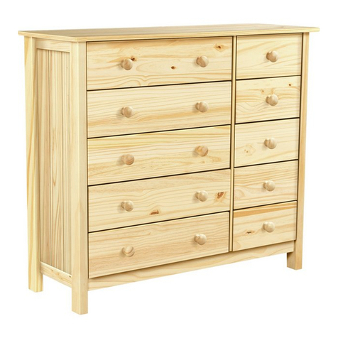
Canterbury 4 DRW CHEST
Assembly Instructions - Please save for future reference
565/2178
572/6080
553/4801
Dimensions
Width - 84.3cm
Depth - 41.9cm
Height - 99.7cm
Important – Please read these instructions carefully before starting the assembly
If you need help or have damaged or missing parts, call the Customer Helpline:
Argos = 0345 6400800
71944 Version B Date 11/09/2017
max.
lbs
kg
25
55
lbs
kg
9
20
71944
-50
71944
A01
www.tvilum.com
2
Safety and Care Advice
Important – Please read these instructions carefully before starting assembly
Note: If required, the next
page can be cut out and used
as reference throughout the
assembly. Keep this page with
these instructions for future
reference.
• Check you have all the
components and tools listed on
the following pages.
• Remove all ttings from the
plastic bags and separate them
into their groups.
• Keep children and animals
away from the work area, small
parts could choke if swallowed.
• Make sure you have enough
space to lay out the parts before
starting.
• During assembly, do not stand
or put weight on the product,
this could cause damage.
• Assemble the item as close
to its nal position (in the same
room) as possible.
• Assemble on a soft level
surface to avoid damaging the
unit or your oor.
• Parts of the assembly will be
easier with 2 people.
• We do not
recommend the use
of power drivers for
inserting screws, as
this could damage
the unit. Only use hand screw
drivers.
• Only clean using a damp cloth
and mild detergent, do no use
bleach or abrasive cleaners.
• From time to time check that
there are no loose screws on
this unit.
• This product should not be
discarded with household waste.
Take to your local authority
waste disposal centre.
Care and maintenance
Skin contact: Remove
contamination by washing with
soap and water. This procedure
should also be followed prior to
eating and drinking.
Eye contact: Rinse immediately
with clean water for 15 minutes
and seek medical advice.
If swallowed: Seek medical
advice immediately.
Glue safety - Take care when using glue, please follow the advice below
• The provided tip-over restraint
must be installed in order to
optimize user safety.
Safety
3
Components - Panels
Please check that you have all the panels listed below
If you have damaged or missing components, call the
Customer Helpline: Argos = 0345 6400800
00753
Right drawer side
(34.5 x 14cm ) x4
00754
Left drawer side
(34.5 x 14cm) x4
03333
Drawer back
(72.2 x 14cm) x4
06080
Drawer bottom
(73.3 x 34.2cm) x4
09665
Back panel
(97.3 x 76.4cm)
76425
Profile side
(41.5 x 2.5cm) x2
76426
Profile side
(41.5 x 2.5cm) x2
76315
Profile front
(83.5 x 2.5 cm) x2
76316
Base rail
(75.4 x 3.1 cm)
EC
Drawer front
(75.1 x 22.1cm) x4
FN
Side panel
(96.4 x 39 cm) x2
IA
Bottom panel (84.3 x 41.9cm)
LA
Top panel (84.3 x 41.9cm)
71944
-50
4
Please check that you have all the ttings as listed below
Note: The quantities listed below are the correct amounts to complete the assembly.
In some cases, more ttings may be supplied than required.
Components - Fittings
Ruler - Use this ruler to help correctly identify the screws
Tools required
94066
Stabilizer x1
Cross head screwdriver
(medium & large)
Wooden block
Flathead screwdriver
(medium)
Ruler
Eye protection
(when using a
hammer or glue)
01 02 03 04 05 06 07 08 09 0 100 110 120 130 140 150
01 23 45 6
Hammer
Tape measure
Panel clips x8
10401
Tape dots x1
17414
Dowel (ø5 x 30mm) x31
20203
Drawer fastener x16
20228
Glue x1
22601
Flat head screw (ø3,5 x 15mm) x16
25233
Screw (ø4 x 13mm) x12
25440
Flat head screw (ø5,8 x 9mm) x18
26020
Flat head screw (ø6,3 x 27mm) x7
26033
Machine screw (M4 x 9mm) x8
26214
Machine screw (M4 x 23mm) x8
26232
Cam bolt x16
31513
Cam x16
31687
Wedges x4
33204
Floor glider x4
63008
Handle x8
81040
Strap x2
94009
Drawer runner x8
41404
Drawer bottom support x4
10510
Awl
5
Assembly Instructions
Step 1
Fittings you will need for this step:
Cam bolt
#31513 x8
Insert cam bolts
Insert cam bolts 31513
into the holes on top and
bottom panel LA .
The cam bolts must be
screwed ush down with
the surfaces.
FN
(x2)
IA
LA
07-09-2017_JTJA:
OBS:
Billedramme samt billede er gemt under "Skjult" lag.
Dette skyldes, at samlevejledningen gemmes til AI, og for at
sørge for, at der ikke automatisk kommer disse billedrammer
med i eksporteringen, hvorved man ikke skal rette AI filen
efterfølgende og manuelt.
DETTE ER BILLEDE 1 & 2
Step 2
Insert dowles
Insert dowels 20203
into outer holes on the
ends of side panels FN .
Place cam 31687 into
the holes on top of side
panel FN .
Make sure that the
arrows on the cams are
facing the edges of the
panels as illustrated.
Dowel
#20203 x8
Fittings you will need for this step:
Cam
#31687 x8
6
5.
27
4.
15
3.
25
4
2.
1.
1 27
3
10
17
1
FNFN
24
07-09-2017_JTJA:
OBS:
Billedramme samt billede er gemt under "Skjult" lag.
Dette skyldes, at samlevejledningen gemmes til AI, og for at
sørge for, at der ikke automatisk kommer disse billedrammer
med i eksporteringen, hvorved man ikke skal rette AI filen
efterfølgende og manuelt.
DETTE ER BILLEDE 3
Front
Front
Front
Assembly Instructions
Step 3 Fittings you will need for this step:
Flat head screw
#26020 x16
Flat head screw
#25233 x16
Drawer runner
#41404 x8
Place drawer runners
1.
Extend drawer runner
41404 and make sure to
note which way it runs.
2.
Place drawer runner
41404 so that they face
the fronts of side panels
F . Next, screw in at
head screw 26020 into
hole no. 4 as illustrated.
3.
Adjust drawer runner
41404 as illustrated and
screw in at head screw
26020 into hole no. 25.
4.
Likewise, extend drawer
runner 41404 and nd
hole no. 15 as illustrated.
Then, use an awl before
screwing in at head
screw 25233 .
5.
Lastly, use an awl and
screw in at head screw
25233 in hole no. 27 as
illustrated.
Repeat these 5steps for
the remaining runners.
7
Assembly Instructions
Step 4
Attach bottom panel
Place cam bolts from the
bottom panel IA into
the holes in the ends of
side panels FN .
Make sure that the
nished edges are facing
towards the front and
that the unnished sides
are facing towards the
bottom of the cabinet.
When pushed together,
tighten the cams as
illustrated.
9,8 cm
19,4 cm
IA
FN
FN
FN
IA
FN
07-09-2017_JTJA:
OBS:
Billedramme samt billede er gemt under "Skjult" lag.
Dette skyldes, at samlevejledningen gemmes til AI, og for at
sørge for, at der ikke automatisk kommer disse billedrammer
med i eksporteringen, hvorved man ikke skal rette AI filen
efterfølgende og manuelt.
DETTE ER BILLEDE 4
8
Assembly Instructions
Step 5
Attach back panel
Slide back panel 09665
smoothly down into the
grooves in the side and
bottom panel FN .
IA
FN
FN
09665
07-09-2017_JTJA:
OBS:
Billedramme samt billede er gemt under "Skjult" lag.
Dette skyldes, at samlevejledningen gemmes til AI, og for at
sørge for, at der ikke automatisk kommer disse billedrammer
med i eksporteringen, hvorved man ikke skal rette AI filen
efterfølgende og manuelt.
DETTE ER BILLEDE 5
9
9,8 cm
IA
LA
FN
09665
FN
x2
76426
76315
76425
07-09-2017_JTJA:
OBS:
Billedramme samt billede er gemt under "Skjult" lag.
Dette skyldes, at samlevejledningen gemmes til AI, og for at
sørge for, at der ikke automatisk kommer disse billedrammer
med i eksporteringen, hvorved man ikke skal rette AI filen
efterfølgende og manuelt.
DETTE ER BILLEDE 6 & 7
Assembly Instructions
Step 6
Step 7
Assemble proles
Insert wedges 33204
into slots on the angle
ends of side and front
proles 76315 + 76425
+ 76426 .
Please use a hammer for
this step.
Fittings you will need for this step:
Wedges
#33204 x4
Attach top panel
Place the cam bolts from
top panel LA into the
end holes on side panels
FN .
When pushed together,
tighten the cams as
illustrated.
Top
Bottom
9,8 cm
IA
LA
FN
09665
FN
x2
76426
76315
76425
07-09-2017_JTJA:
OBS:
Billedramme samt billede er gemt under "Skjult" lag.
Dette skyldes, at samlevejledningen gemmes til AI, og for at
sørge for, at der ikke automatisk kommer disse billedrammer
med i eksporteringen, hvorved man ikke skal rette AI filen
efterfølgende og manuelt.
DETTE ER BILLEDE 6 & 7
10
Assembly Instructions
Step 9
Step 8 Fittings you will need for this step:
Fittings you will need for this step:
Flat head screw
#26033 x7
Glue
#22601 x1
Dowel
#20203 x7
Add glue
Insert dowels 20203
into outer holes on the
assembled prole. Use
glue 22601 as shown.
Add one small drop of
glue per hole.
Attach prole
Push the prole down
as it reaches the bottom
panel IA . Use at head
screw 26033 to tighten.
max 9 mm
76425
76315 76426
IA
LA
FN
09665
FN
07-09-2017_JTJA:
OBS:
Billedramme samt billede er gemt under "Skjult" lag.
Dette skyldes, at samlevejledningen gemmes til AI, og for at
sørge for, at der ikke automatisk kommer disse billedrammer
med i eksporteringen, hvorved man ikke skal rette AI filen
efterfølgende og manuelt.
DETTE ER BILLEDE 8 & 9
11
Assembly Instructions
Step 10
Step 11
Fittings you will need for this step:
Tape dots
#17414 x1
Glue
#22601 x1
Attach tape dots
Attach the tape dots
17414 on the base rail
76316 .
Attach assembled
prole
Add glue 22601 in holes
of the top panel LA .
Add one small drop of
glue per hole.
Place the assembled pro-
le as shown and press
down (dowels going into
dedicated holes).
76316
LA
IA
FN
09665
FN
07-09-2017_JTJA:
OBS:
Billedramme samt billede er gemt under "Skjult" lag.
Dette skyldes, at samlevejledningen gemmes til AI, og for at
sørge for, at der ikke automatisk kommer disse billedrammer
med i eksporteringen, hvorved man ikke skal rette AI filen
efterfølgende og manuelt.
DETTE ER BILLEDE 10 & 11
12
Assembly Instructions
Step 12
Attach base rail
Flip the cabinet so that
it stands on its bottom
panel IA .
Then pull of the paper
from the tape dots and
place the base rail
76316 behind the
assembled prole.
Push forward as
illustrated with the arrow.
Step 13
Fittings you will need for this step:
Flat head screw
#26020 x2
Stabilizer
#94066 x1
Attach stabilizer
Place the stabilizer
94066 between the two
side panels FN . See the
detail drawing for correct
orientation.
Use the at head screw
26020 to tighten the
stabilizer.
LA
IA
76316
FN
09665
FN
LA
IA
FN
FN
09665
07-09-2017_JTJA:
OBS:
Billedramme samt billede er gemt under "Skjult" lag.
Dette skyldes, at samlevejledningen gemmes til AI, og for at
sørge for, at der ikke automatisk kommer disse billedrammer
med i eksporteringen, hvorved man ikke skal rette AI filen
efterfølgende og manuelt.
DETTE ER BILLEDE 12 & 13
LA
IA
76316
FN
09665
FN
LA
IA
FN
FN
09665
07-09-2017_JTJA:
OBS:
Billedramme samt billede er gemt under "Skjult" lag.
Dette skyldes, at samlevejledningen gemmes til AI, og for at
sørge for, at der ikke automatisk kommer disse billedrammer
med i eksporteringen, hvorved man ikke skal rette AI filen
efterfølgende og manuelt.
DETTE ER BILLEDE 12 & 13
13
IA
FN
09665
LA
FN
09665
FN
IA
FN
LA
07-09-2017_JTJA:
OBS:
Billedramme samt billede er gemt under "Skjult" lag.
Dette skyldes, at samlevejledningen gemmes til AI, og for at
sørge for, at der ikke automatisk kommer disse billedrammer
med i eksporteringen, hvorved man ikke skal rette AI filen
efterfølgende og manuelt.
DETTE ER BILLEDE 14 & 15
Assembly Instructions
Step 14 Fittings you will need for this step:
Panel clips
#10401 x8
Fittings you will need for this step:
Floor Glider
#63008 x4
Step 15
Attach oor gliders
Place the oor gliders
63008 in the holes of
bottom panel IA .
Use a wodden block
between a hammer and
the oor gliders.
Attach back panels
Important:
The unit MUST be
square when the panel
clips is attached.
Lay the cabinet face
down on the oor. To
stabilize the back panel,
use the panel clips
10401 . Press forward
the thin tabs between
the back panel and the
groove, and then tighten
with a screwdriver.
IA
FN
09665
LA
FN
09665
FN
IA
FN
LA
07-09-2017_JTJA:
OBS:
Billedramme samt billede er gemt under "Skjult" lag.
Dette skyldes, at samlevejledningen gemmes til AI, og for at
sørge for, at der ikke automatisk kommer disse billedrammer
med i eksporteringen, hvorved man ikke skal rette AI filen
efterfølgende og manuelt.
DETTE ER BILLEDE 14 & 15
14
94009
3 cm
IA
LA
FN
FN
09665
07-09-2017_JTJA:
OBS:
Billedramme samt billede er gemt under "Skjult" lag.
Dette skyldes, at samlevejledningen gemmes til AI, og for at
sørge for, at der ikke automatisk kommer disse billedrammer
med i eksporteringen, hvorved man ikke skal rette AI filen
efterfølgende og manuelt.
DETTE ER BILLEDE 16
Assembly Instructions
Step 16
Fittings you will need for this step:
Strap
#94009 x2
Fix the unit to a wall
with the strap
Fix the unit to a wall with
strap 94009 .
The screw supplied
together with the anti-
topple bracket is to be
used only for xing the
anti-topple bracket to
the furniture. In addition
to this, you will need
to choose a screw or a
tting which is suitable
for securing the bracket
to the kind of wall you
have. If you are unsure
about what type of screw
to use contact your local
hardware store.
15
00754
00753
x4
EC
07-09-2017_JTJA:
OBS:
Billedramme samt billede er gemt under "Skjult" lag.
Dette skyldes, at samlevejledningen gemmes til AI, og for at
sørge for, at der ikke automatisk kommer disse billedrammer
med i eksporteringen, hvorved man ikke skal rette AI filen
efterfølgende og manuelt.
DETTE ER BILLEDE 17
Assembly Instructions
Step 17 Fittings you will need for this step:
Cam
#31687 x8
Dowel
#20203 x16
Cam bolt
#31513 x8
Assemble drawers
Attach cam 31687 into
the holes in left and right
drawer side 00754 +
00753 .
Make sure that the cams’
arrows are facing the
edges of the panels as
illustrated.
Screw the cam bolt
31513 in the drawer
front EE .
Cam bolts must be
screwed down ush with
the surface.
16
Assembly Instructions
Step 18
Step 19
Fittings you will need for this step:
Screw
#20228 x16
Assemble drawers
Align holes at back of the
drawer sides 00754 +
00753 with the holes on
the drawer back 03333 .
Make sure the grooves
are facing the inner side
of the drawer.
Tap drawer fasteners
20228 into place with a
hammer.
Assemble drawer
bottom
Press the drawer bottom
06080 smoothly in the
grooves (nished side
up).
x4
00753
00754
03333
x4
06080
00754
00753
03333
07-09-2017_JTJA:
OBS:
Billedramme samt billede er gemt under "Skjult" lag.
Dette skyldes, at samlevejledningen gemmes til AI, og for at
sørge for, at der ikke automatisk kommer disse billedrammer
med i eksporteringen, hvorved man ikke skal rette AI filen
efterfølgende og manuelt.
DETTE ER BILLEDE 18 & 19
71944
-50
x4
00753
00754
03333
x4
06080
00754
00753
03333
07-09-2017_JTJA:
OBS:
Billedramme samt billede er gemt under "Skjult" lag.
Dette skyldes, at samlevejledningen gemmes til AI, og for at
sørge for, at der ikke automatisk kommer disse billedrammer
med i eksporteringen, hvorved man ikke skal rette AI filen
efterfølgende og manuelt.
DETTE ER BILLEDE 18 & 19
71944
-50
17
Assembly Instructions
Step 20
Step 21
Fittings you will need for this step:
Handle
#81040 x8
Machine screw
#26232 x8
Assemble drawer front
Attach the drawer front
EE by placing dowels
and cam bolts in the cor-
rect holes. See the detail
drawing.
Once pushed together,
tighten the cams as illus-
trated.
Attach handles
Attach the handle 81040
to the drawer front EE .
Use machine screw
26232 to attach the
handle.
x4
06080
03333
EC
00754
00753
x4
03333
00753
00754
06080
EC
07-09-2017_JTJA:
OBS:
Billedramme samt billede er gemt under "Skjult" lag.
Dette skyldes, at samlevejledningen gemmes til AI, og for at
sørge for, at der ikke automatisk kommer disse billedrammer
med i eksporteringen, hvorved man ikke skal rette AI filen
efterfølgende og manuelt.
DETTE ER BILLEDE 20 & 21
x4
06080
03333
EC
00754
00753
x4
03333
00753
00754
06080
EC
07-09-2017_JTJA:
OBS:
Billedramme samt billede er gemt under "Skjult" lag.
Dette skyldes, at samlevejledningen gemmes til AI, og for at
sørge for, at der ikke automatisk kommer disse billedrammer
med i eksporteringen, hvorved man ikke skal rette AI filen
efterfølgende og manuelt.
DETTE ER BILLEDE 20 & 21
18
Assembly Instructions
Step 22
Attach drawer
bottom support
Place the drawer bottom
support 10510 on the
bottom of the drawers.
See the detail drawing,
for correct orientation.
Use the screw 25440 to
attach the drawer bottom
support.
Fittings you will need for this step:
Drawer bottom support
#10510 x4
Step 23
Mount the drawers
Pull out all the runners
before mounting the
drawers.
Screw
#25440 x12
DU
06080
03333
EC
00753
00754
DR
FN
09665
FN
IA
LA
07-09-2017_JTJA:
OBS:
Billedramme samt billede er gemt under "Skjult" lag.
Dette skyldes, at samlevejledningen gemmes til AI, og for at
sørge for, at der ikke automatisk kommer disse billedrammer
med i eksporteringen, hvorved man ikke skal rette AI filen
efterfølgende og manuelt.
DETTE ER BILLEDE 22 & 23
19
Mount the drawers
Place the drawers
between 2 drawer
runners each.
See illustration for
reference.
Make sure that the
drawer runners are
pushed into the grooves
of the drawer, touching
the drawer front.
Fix the drawer runners
with machine screw
26214 from the inside of
the drawer in both sides.
Repeat this procedure
for each of the remaining
drawers.
Assembly Instructions
Step 24
Fittings you will need for this step:
Machine screw
#26214 x8
If you need help or have damaged or missing parts, call the Customer Helpline:
Argos = 0345 6400800
Assembly is complete.
# $PRPVIEW:{Pos_Beslag}
x8
EC
EC
EC
EC
EC
DP
Drawer front
?
07-09-2017_JTJA:
OBS:
Billedramme samt billede er gemt under "Skjult" lag.
Dette skyldes, at samlevejledningen gemmes til AI, og for at
sørge for, at der ikke automatisk kommer disse billedrammer
med i eksporteringen, hvorved man ikke skal rette AI filen
efterfølgende og manuelt.
DETTE ER BILLEDE 24
71944
-50

This manual suits for next models

2

Other Argos Home Indoor Furnishing manuals

Argos Home Apartment Mirror 299/8426 User manual

Argos Home

Argos Home Apartment Mirror 299/8426 User manual

Argos Home Normandy 5+2 Drawer Chest of Drawers User manual

Argos Home

Argos Home Normandy 5+2 Drawer Chest of Drawers User manual

Argos Home New Hallingford 652/9482 User manual

Argos Home

Argos Home New Hallingford 652/9482 User manual

Argos Home Gloss Tall Boy White 393/2780 User manual

Argos Home

Argos Home Gloss Tall Boy White 393/2780 User manual

Argos Home Tongue & Groove 344/7794 User manual

Argos Home

Argos Home Tongue & Groove 344/7794 User manual

Argos Home 725/5573 User manual

Argos Home

Argos Home 725/5573 User manual

Argos Home Scandinavia 6423801 User manual

Argos Home

Argos Home Scandinavia 6423801 User manual

Argos Home Capella 255/7276 User manual

Argos Home

Argos Home Capella 255/7276 User manual

Argos Home 313/5226 User manual

Argos Home

Argos Home 313/5226 User manual

Argos Home Matrix Round Glass Lamp Table User manual

Argos Home

Argos Home Matrix Round Glass Lamp Table User manual

Argos Home Dutch Glam 821/3507 User manual

Argos Home

Argos Home Dutch Glam 821/3507 User manual

Argos Home Chrome Double Tidy Rail HD 171/7639 User manual

Argos Home

Argos Home Chrome Double Tidy Rail HD 171/7639 User manual

Argos Home Ohio 322/3468 User manual

Argos Home

Argos Home Ohio 322/3468 User manual

Argos Home Tongue and Groove 326/3002 User manual

Argos Home

Argos Home Tongue and Groove 326/3002 User manual

Argos Home Tongue and Groove Corner Shelf 488/2884 User manual

Argos Home

Argos Home Tongue and Groove Corner Shelf 488/2884 User manual

Argos Home Ohio TV Unit 309/6561 User manual
Argos Home

Argos Home Ohio TV Unit 309/6561 User manual

Argos Home lslington 803/4786 User manual

Argos Home

Argos Home lslington 803/4786 User manual

Argos Home Banbury Dining Chair 632/3846 User manual

Argos Home

Argos Home Banbury Dining Chair 632/3846 User manual

Argos Home Crystal 3ft Frame 697/0536 User manual

Argos Home

Argos Home Crystal 3ft Frame 697/0536 User manual

Argos Home Tongue and Groove Corner Cabinet 363/3481 User manual

Argos Home

Argos Home Tongue and Groove Corner Cabinet 363/3481 User manual

Argos Home Rosie 711/5596 Datasheet

Argos Home

Argos Home Rosie 711/5596 Datasheet

Argos Home 502/5509 User manual

Argos Home

Argos Home 502/5509 User manual

Argos Home 403/9448 User manual

Argos Home

Argos Home 403/9448 User manual

Argos Home Grey And Chrome Tidy Rail With Two Rails... User manual

Argos Home

Argos Home Grey And Chrome Tidy Rail With Two Rails... User manual

Popular Indoor Furnishing manuals by other brands

Noblewell NWOC6 instruction manual

Noblewell

Noblewell NWOC6 instruction manual

Kingfisher 5059340400273 manual

Kingfisher

Kingfisher 5059340400273 manual

SMITH SYSTEM 56000E Assembly instructions

SMITH SYSTEM

SMITH SYSTEM 56000E Assembly instructions

Costway 14708635 user manual

Costway

Costway 14708635 user manual

LDI Spaces SAFCO 3505 Assembly instructions

LDI Spaces

LDI Spaces SAFCO 3505 Assembly instructions

Munchkin MK0016 manual

Munchkin

Munchkin MK0016 manual

Serta Dream Convertibles Corey Assembly instructions

Serta

Serta Dream Convertibles Corey Assembly instructions

Dunelm Lisbon 30276687 instructions

Dunelm

Dunelm Lisbon 30276687 instructions

Mr IRONSTONE SB05 Assembly instructions

Mr IRONSTONE

Mr IRONSTONE SB05 Assembly instructions

Courtyard Creations RTS487G Assembly instructions

Courtyard Creations

Courtyard Creations RTS487G Assembly instructions

Gladiator GEARLOFT GAWA45SFTG Assembly instructions

Gladiator

Gladiator GEARLOFT GAWA45SFTG Assembly instructions

ZINUS SmartBase instructions

ZINUS

ZINUS SmartBase instructions

Beurer BS 89 Instructions for use

Beurer

Beurer BS 89 Instructions for use

VECELO KHD-XF-MR01-BLK Assembly instructions

VECELO

VECELO KHD-XF-MR01-BLK Assembly instructions

modway MOD-5478 quick start guide

modway

modway MOD-5478 quick start guide

HAIDER BIOSWING 670 iQ instruction manual

HAIDER BIOSWING

HAIDER BIOSWING 670 iQ instruction manual

JAMES MARTIN VANITIES 388-V36-CFO-A Assembly instructions

JAMES MARTIN VANITIES

JAMES MARTIN VANITIES 388-V36-CFO-A Assembly instructions

Richelieu ELEFU installation guide

Richelieu

Richelieu ELEFU installation guide

manuals.online logo
manuals.online logoBrands
  • About & Mission
  • Contact us
  • Privacy Policy
  • Terms and Conditions

Copyright 2025 Manuals.Online. All Rights Reserved.