©
UPLIFT
Desk
• 800-349-3839 • 512-614-3152 • inf[email protected]om • upliftdesk.com4
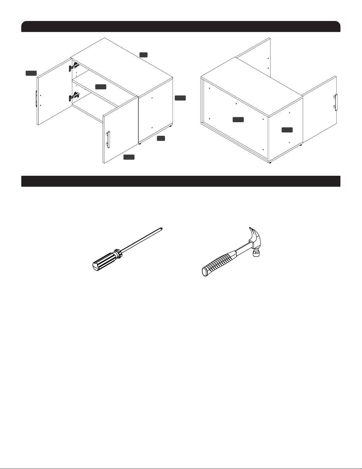
PACKAGE CONTENTS
Bottom Panel
(qty 1)
Top Panel
(qty 1)
Right Side Panel
(qty 1)
Left Side Panel
(qty 1)
Back Panel
(qty 1)
Doors
(qty 2)
Shelf
(qty 1)
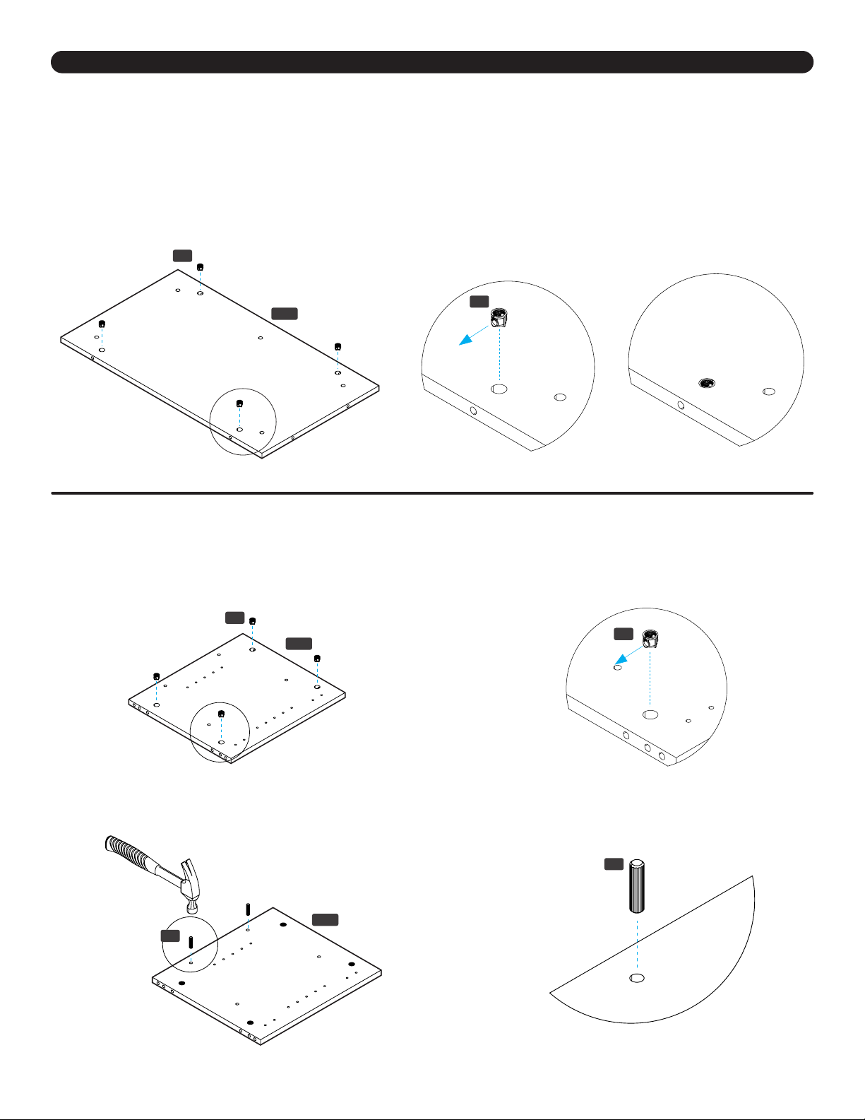
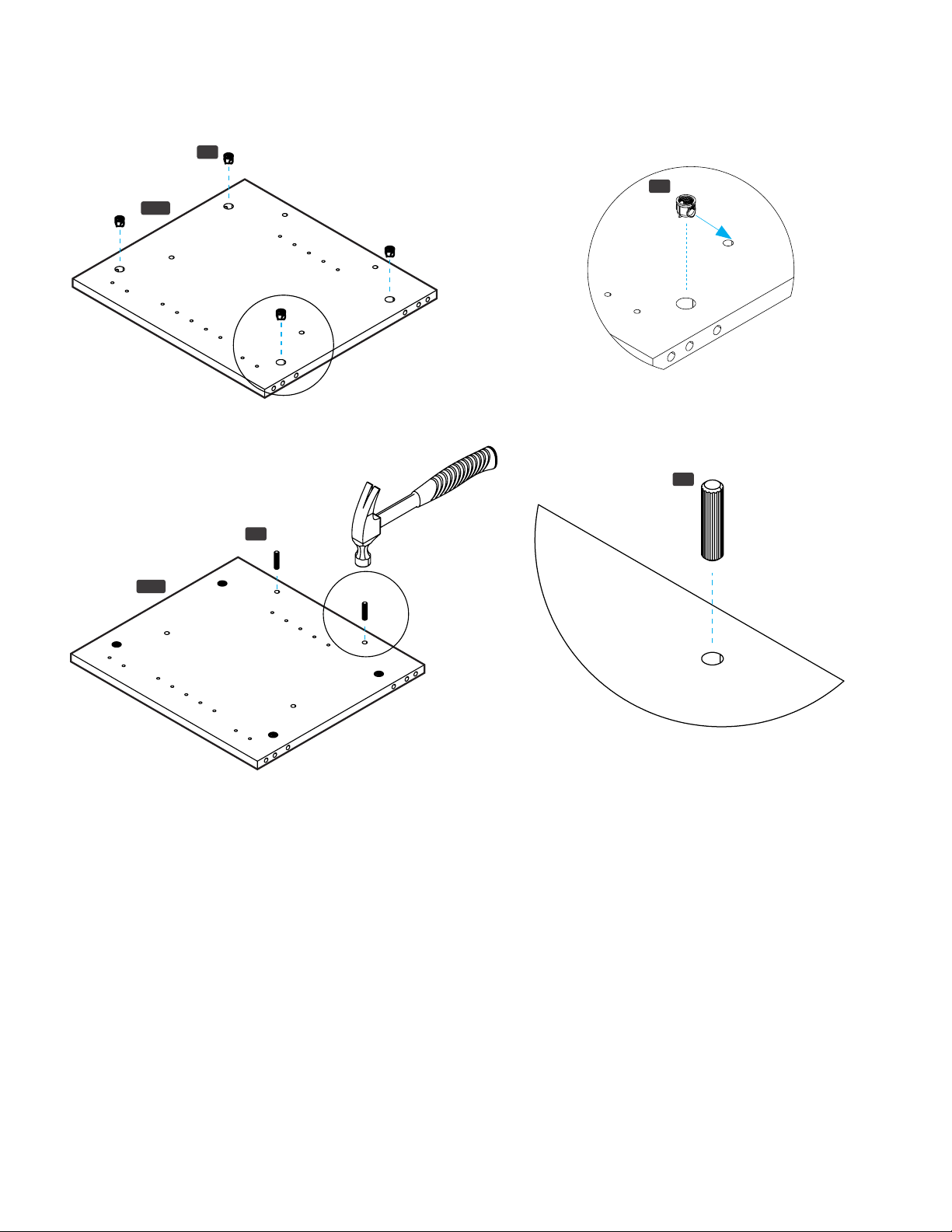
Cam
Lock Barrels
(qty 12)
Cam
Lock Pins
(qty 12)
Cam Lock
Set Screws
(qty 12)
CODE QTY CODE QTY
C1-Bottom
Panel
C2-Right Side
Panel
C3-Left Side
Panel
C4-Top
Panel
C5-Back
Panel
C6-Shelf
C7-Door 2
1
1
1
1
1
1
CODE QTY CODE QTY
C1-Bottom
Panel
C2-Right Side
Panel
C3-Left Side
Panel
C4-Top
Panel
C5-Back
Panel
C6-Shelf
C7-Door 2
1
1
1
1
1
1
CODE QTY CODE QTY
C1-Bottom
Panel
C2-Right Side
Panel
C3-Left Side
Panel
C4-Top
Panel
C5-Back
Panel
C6-Shelf
C7-Door 2
1
1
1
1
1
1
CODE QTY CODE QTY
C1-Bottom
Panel
C2-Right Side
Panel
C3-Left Side
Panel
C4-Top
Panel
C5-Back
Panel
C6-Shelf
C7-Door 2
1
1
1
1
1
1
CODE QTY CODE QTY
C1-Bottom
Panel
C2-Right Side
Panel
C3-Left Side
Panel
C4-Top
Panel
C5-Back
Panel
C6-Shelf
C7-Door 2
1
1
1
1
1
1
CODE QTY CODE QTY
C1-Bottom
Panel
C2-Right Side
Panel
C3-Left Side
Panel
C4-Top
Panel
C5-Back
Panel
C6-Shelf
C7-Door 2
1
1
1
1
1
1
CODE QTY CODE QTY
C1-Bottom
Panel
C2-Right Side
Panel
C3-Left Side
Panel
C4-Top
Panel
C5-Back
Panel
C6-Shelf
C7-Door 2
1
1
1
1
1
1
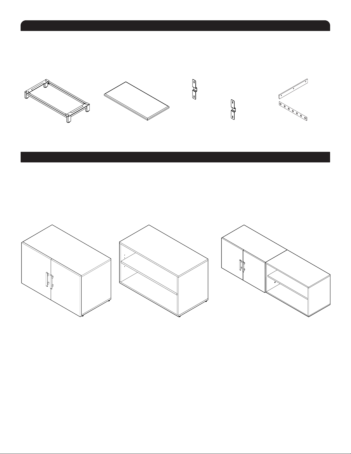
HARDWARE
Wood
Dowels
(qty 16)
Leveling
Glides
(qty 4)
Hinges
with Fasteners
(qty 4)
Handles
with Fasteners
(qty 2)
Shelf
Pins
(qty 4)
Hole
Covers
(qty 24)
M6x13
Side-by-Side
Connector Screw
(qty 2)
M6x30
Side-by-Side
Connector Nut
(qty 2)
Pads
for Stacking
(qty 8)
Security
Strap Kit
(qty 1)
CODE QTY
H1- Cam Lock Pin
H2- Cam Lock Barrel
H3- Cam Lock Set Screw
H4- Wood Dowel
H5- Leveling Glides
H6- Hinges With Fasteners
H7- Handle With Fasteners
H8- Shelf Pins
H9- Hole Covers
Security Strap Kit
12
12
12
16
4
4
2
4
1 Sheet
1
H10- M6x13 Binding Post
Machine Screw
H11- M6x13 Binding Post
H2- Felt Pads for stacking
2
2
8
P5P4
P3
P6
P2P1
H3H2H1
P7
H4 H5 H6 H7
H8 H9 H10 H11 H12