RTD Embedded Technologies, Inc. | www.rtd.com iv VID34860ER User’s Manual
Table of Contents
1Introduction 6
Product Overview........................................................................................................................................................................ 6
Board Features ........................................................................................................................................................................... 6
Ordering Information................................................................................................................................................................... 6
Contact Information .................................................................................................................................................................... 7
1.4.1 Sales Support 7
1.4.2 Technical Support 7
2Specifications 8
Operating Conditions .................................................................................................................................................................. 8
Electrical Characteristics ............................................................................................................................................................ 8
3Board Connection 9
Board Handling Precautions ....................................................................................................................................................... 9
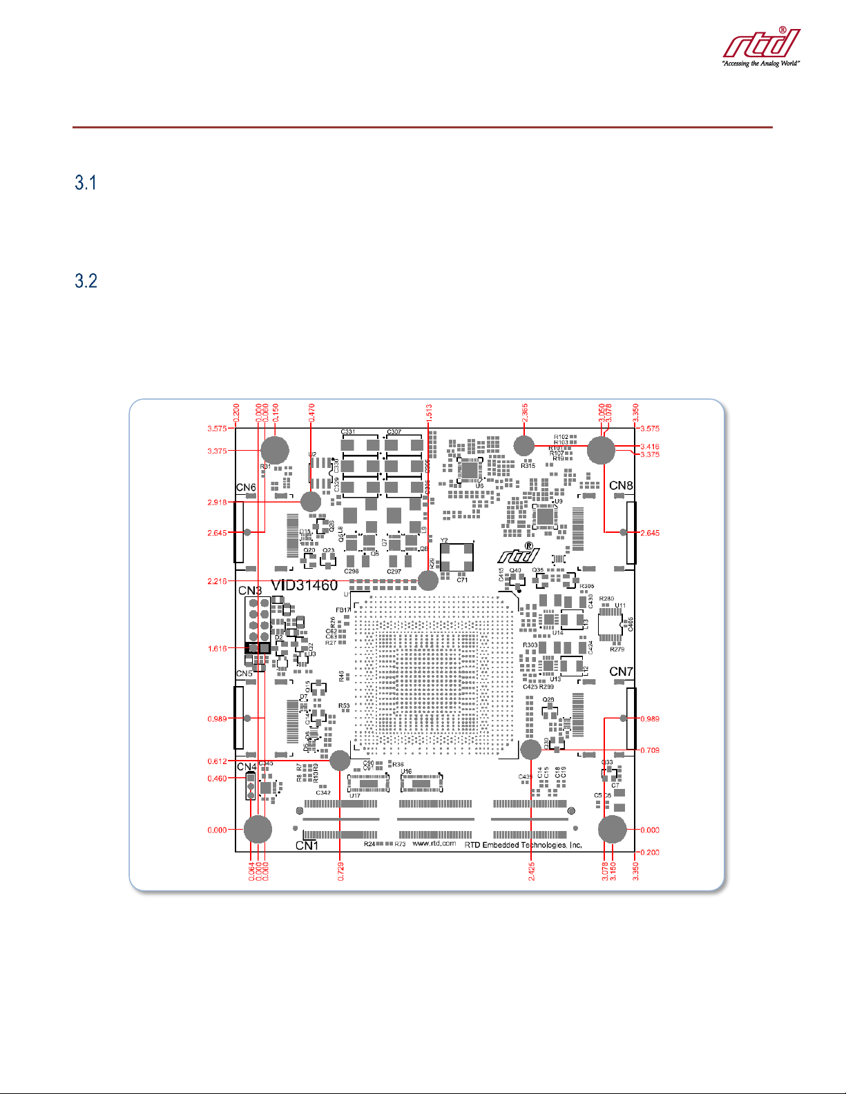
Physical Characteristics.............................................................................................................................................................. 9
3.2.1 Thermal Management 10
Connectors and Jumpers.......................................................................................................................................................... 11
3.3.1 External I/O Connectors 11
CN3: VGA Connector 11
CN4: Fan Header 11
CN5, CN6, CN7 & CN8: DisplayPort Connector 12
3.3.2 Bus Connectors 12
CN1 (Top) & CN2 (Bottom): PCIe Connector 12
Steps for Installing .................................................................................................................................................................... 13
4IDAN Connections 14
Module Handling Precautions................................................................................................................................................... 14
Physical Characteristics............................................................................................................................................................ 14
Connectors................................................................................................................................................................................ 15
4.3.1 External I/O Connectors 15
VGA Connector 15
DisplayPort Connector 15
4.3.2 Bus Connectors 15
CN1 (Top) & CN2 (Bottom): PCIe Connector 15
Steps for Installing .................................................................................................................................................................... 16
5Functional Description 17
Block Diagram........................................................................................................................................................................... 17
AMD GPU Controller ................................................................................................................................................................ 17
5.2.1 Multiple Displays 17
6Software 18
Drivers....................................................................................................................................................................................... 18
7Troubleshooting 19
8Additional Information 20
PC/104 Specifications............................................................................................................................................................... 20
PCI and PCI Express Specification .......................................................................................................................................... 20
9Limited Warranty 21