rtd USB25407 User manual

RTD Embedded Technologies, Inc.
AS9100 and ISO 9001 Certified
USB25407 and USB35407
PCI Express USB 3.0
User’s Manual
BDM-610020101 Rev. B

RTD Embedded Technologies, Inc.
103 Innovation Boulevard
State College, PA 16803 USA
Telephone: 814-234-8087
Fax: 814-234-5218
www.rtd.com

RTD Embedded Technologies, Inc. | www.rtd.com iii USB25407 User’s Manual
Revision History
Rev A Initial Release
Rev B Updated trademark text
Correct trademarks for IDAN, HiDAN, and HiDANplus throughout
Section 1.3: Corrected IDAN ordering part numbers
Section 3.2: Updated board dimensional drawing to include I/O connectors
Section 3.4: Indicate that STEP models are available upon request
Section 5.4: Corrected driver type to “USB” driver
Advanced Analog I/O, Advanced Digital I/O, aAIO, aDIO, a2DIO, Autonomous SmartCal, “Catch the Express”, cpuModule, dspFramework, dspModule, eBuild, expressMate, ExpressPlatform, “MIL Value for COTS
prices”, multiPort, PlatformBus, and PC/104EZ are trademarks, and “Accessing the Analog World”, dataModule, IDAN, HiDAN, HiDANplus, RTD, the RTD logo, and StackNET are registered trademarks of RTD
Embedded Technologies, Inc. (formerly Real Time Devices, Inc.). PS/2 is a trademark of International Business Machines Inc. PCI, PCI Express, and PCIe are trademarks of PCI-SIG. PC/104, PC/104-Plus, PCI-104,
PCIe/104, PCI/104-Express and 104 are trademarks of the PC/104 Consortium. All other trademarks appearing in this document are the property of their respective owners.
Failure to follow the instructions found in this manual may result in damage to the product described in this manual, or other components of the system. The procedure set forth in this manual shall only be performed
by persons qualified to service electronic equipment. Contents and specifications within this manual are given without warranty, and are subject to change without notice. RTD Embedded Technologies, Inc. shall not
be liable for errors or omissions in this manual, or for any loss, damage, or injury in connection with the use of this manual.
Copyright © 2017 by RTD Embedded Technologies, Inc. All rights reserved.

RTD Embedded Technologies, Inc. | www.rtd.com iv USB25407 User’s Manual
Table of Contents
1Introduction 6
Product Overview........................................................................................................................................................................ 6
Board Features ........................................................................................................................................................................... 6
Ordering Information................................................................................................................................................................... 6
Contact Information .................................................................................................................................................................... 7
1.4.1 Sales Support 7
1.4.2 Technical Support 7
2Specifications 8
Operating Conditions .................................................................................................................................................................. 8
Electrical Characteristics ............................................................................................................................................................ 8
3Board Connection 9
Board Handling Precautions ....................................................................................................................................................... 9
Physical Characteristics.............................................................................................................................................................. 9
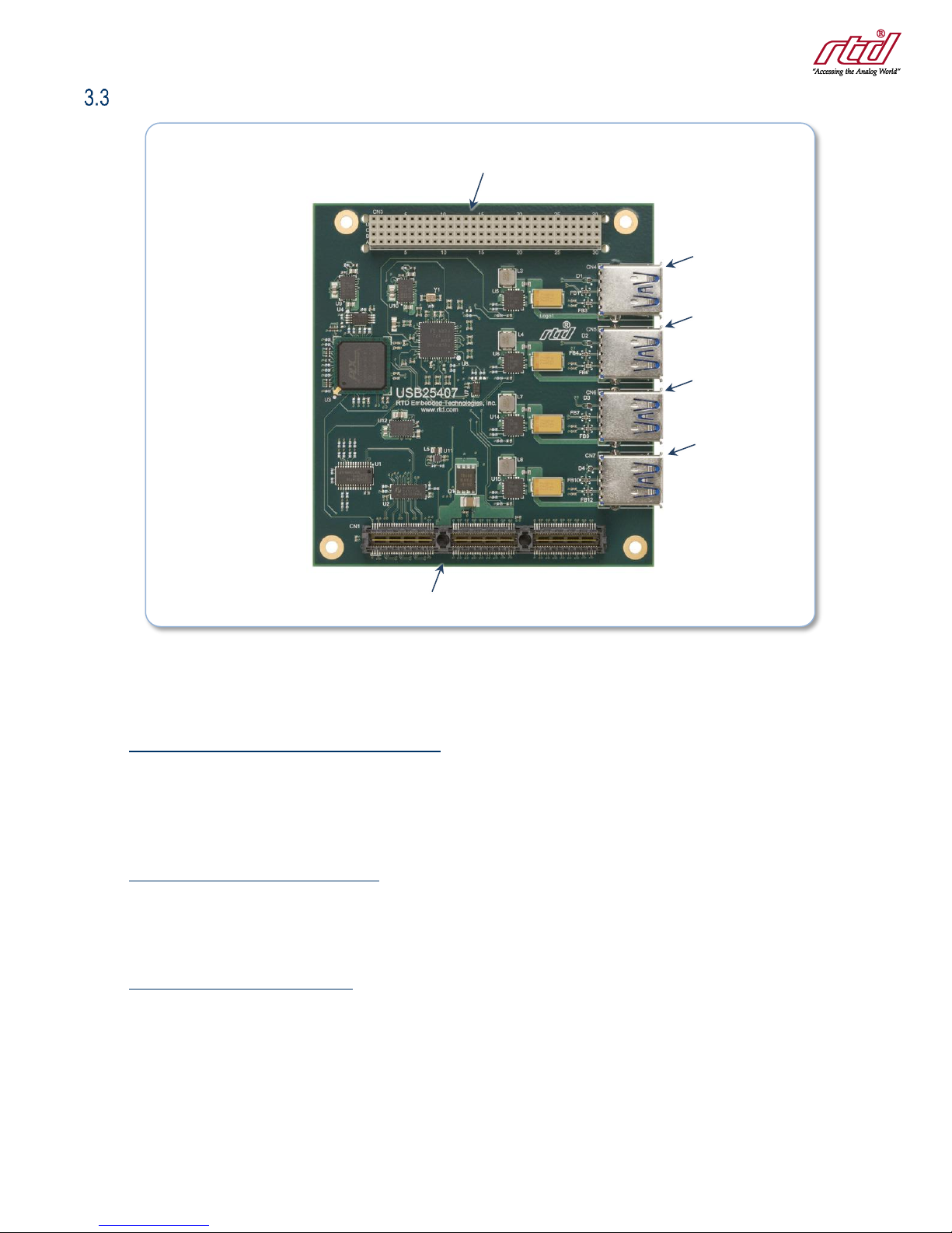
Connectors and Jumpers.......................................................................................................................................................... 10
3.3.1 External I/O Connectors 10
CN4, CN5, CN6 and CN7: USB 3.0 Type A Connectors 10
3.3.2 Bus Connectors 10
CN1 (Top) & CN2 (Bottom): PCIe Connector 10
CN16: PCI Connector (USB25407 only) 10
Steps for Installing .................................................................................................................................................................... 11
4IDAN Connections 12
Module Handling Precautions................................................................................................................................................... 12
Physical Characteristics............................................................................................................................................................ 12
Connectors................................................................................................................................................................................ 13
4.3.1 External I/O Connectors 13
CN4, CN5, CN6 and CN7: USB 3.0 Type A Connectors 13
4.3.2 Bus Connectors 13
CN1 (Top) & CN2 (Bottom): PCIe Connector 13
CN16: PCI Connector (USB25407 only) 13
Steps for Installing .................................................................................................................................................................... 14
5Functional Description 15
Block Diagram........................................................................................................................................................................... 15
Current Limited Boost Converter .............................................................................................................................................. 15
PCI Express Repopulation........................................................................................................................................................ 15
Driver Support........................................................................................................................................................................... 15
6Troubleshooting 16
7Additional Information 17
PC/104 Specifications............................................................................................................................................................... 17
PCI Express Specification ........................................................................................................................................................ 17
8Limited Warranty 18

RTD Embedded Technologies, Inc. | www.rtd.com vUSB25407 User’s Manual
Table of Figures
Figure 1: Board Dimensions ..................................................................................................................................................................................... 9
Figure 2: Board Connections .................................................................................................................................................................................. 10
Figure 3: Example 104™Stack............................................................................................................................................................................... 11
Figure 4: IDAN Dimensions .................................................................................................................................................................................... 12
Figure 5: Example IDAN System ............................................................................................................................................................................ 14
Figure 6: USB25407 Block Diagram....................................................................................................................................................................... 15
Table of Tables
Table 1: Ordering Options ........................................................................................................................................................................................ 6
Table 2: Operating Conditions .................................................................................................................................................................................. 8
Table 3: Electrical Characteristics ............................................................................................................................................................................ 8

RTD Embedded Technologies, Inc. | www.rtd.com 6USB25407 and USB35407 User’s Manual
1Introduction
Product Overview
The USB25407/USB35407 is a four port USB 3.0 controller. This module provide the latest in high-speed connectivity with transfer rates up to
5 Gbps. Advanced connectivity opens the door to high resolution and high frame rates for USB cameras. It also allows USB hard drives to
perform as well as SATA hard drives.
Board Features
The following sections describe the major features of the USB25407 USB 3.0 communication module.
•General Features
oUSB 3.0 xHCI compliant Host Controller
▪PCIe x1 Interface
▪Repopulates PCIe link
▪TI TUSB7340 Controller Chip
oFour Downstream Ports
▪Type A connectors
▪Up to 900mA provided per port
oSupports all USB 3.0 speeds
▪Super Speed (5 Gbit/s)
▪High Speed (480 Mbit/s)
▪Full Speed (12 Mbit/s)
▪Low Speed (1.5 Mbit/s)
oBest-In-Class Adaptive Receive Equalizer Design
▪Maximizes cable length
•Software
oWindows Drivers: XP (32-bit), Windows 7 (32- and 64-bit)
oLinux Support in Kernel (2.6.37 or later)
Ordering Information
The USB25407 is available with the following options:
Table 1: Ordering Options
Part Number
Description
USB25407HR
PCI/104-Express USB 3.0 Module (with pass-through PCI)
USB35407HR
PCIe/104 USB 3.0 Module (without pass-through PCI)
IDAN-USB25407HRS
PCI/104-Express USB 3.0 Module in IDAN enclosure
IDAN-USB35407HRS
PCIe/104 USB 3.0 Module in IDAN enclosure
Throughout this document, USB25407 refers to both the USB25407 and USB35407 unless otherwise noted.
The Intelligent Data Acquisition Node (IDAN®) building block can be used in just about any combination with other IDAN building blocks to
create a simple but rugged 104™ stack. This module can also be incorporated in a custom-built RTD HiDAN®or HiDANplus®High Reliability
Intelligent Data Acquisition Node. Contact RTD sales for more information on our high reliability systems.

RTD Embedded Technologies, Inc. | www.rtd.com 7USB25407 and USB35407 User’s Manual
Contact Information
1.4.1 SALES SUPPORT
For sales inquiries, you can contact RTD Embedded Technologies sales via the following methods:
Phone: 1-814-234-8087 Monday through Friday, 8:00am to 5:00pm (EST).
1.4.2 TECHNICAL SUPPORT
If you are having problems with your system, please try the steps in the Troubleshooting section of this manual.
For help with this product, or any other product made by RTD, you can contact RTD Embedded Technologies technical support via the
following methods:
Phone: 1-814-234-8087 Monday through Friday, 8:00am to 5:00pm (EST).

RTD Embedded Technologies, Inc. | www.rtd.com 8USB25407 and USB35407 User’s Manual
2Specifications
Operating Conditions
Table 2: Operating Conditions
Symbol
Parameter
Test Condition
Min
Max
Unit
Vcc5
5V Supply Voltage
4.75
5.25
V
Vcc3
3.3V Supply Voltage
n/a
n/a
V
Vcc12
12V Supply Voltage
n/a
n/a
V
Vcc-12
-12V Supply Voltage
n/a
n/a
V
Ta
Operating Temperature
-40
+85
C
Ts
Storage Temperature
-55
+125
C
RH
Relative Humidity
Non-Condensing
0
90%
%
MTBF
Mean Time Before Failure
Telcordia Issue 2
30°C, Ground benign, controlled
TBD
Hours
Electrical Characteristics
Table 3: Electrical Characteristics
Symbol
Parameter
Test Condition
Min
Max
Unit
Pd
Power Dissipation
Vcc5 = 5.0V, IPORT = 0A
3.0
W
Icc5
5V Input Supply Current
Active, Board only
600
mA
VPORT
Port voltage output
4.75
5.25
V
IPORT
Current Limit per port
0.9
2.0
A
PCIe Bus
Differential Output Voltage
0.8
1.2
V
DC Differential TX Impedance
95.2
116.9
Ω
Differential Input Voltage
0.175
3.3
V
DC Differential RX Impedance
92.7
115.8
Ω
Electrical Idle Detect Threshold
61
173
mV

RTD Embedded Technologies, Inc. | www.rtd.com 9USB25407 and USB35407 User’s Manual
3Board Connection
Board Handling Precautions
To prevent damage due to Electrostatic Discharge (ESD), keep your board in its antistatic bag until you are ready to install it into your system.
When removing it from the bag, hold the board at the edges, and do not touch the components or connectors. Handle the board in an antistatic
environment, and use a grounded workbench for testing and handling of your hardware.
Physical Characteristics
STEP model is available upon request; contact RTD Tech Support for more information.
•Weight: Approximately 0.07 kg (0.16 lbs.)
•Dimensions: 90.17 mm L x 95.89 mm W (3.550 in L x 3.775 in W)
Figure 1: Board Dimensions

RTD Embedded Technologies, Inc. | www.rtd.com 10 USB25407 and USB35407 User’s Manual
Connectors and Jumpers
Figure 2: Board Connections
3.3.1 EXTERNAL I/O CONNECTORS
CN4, CN5, CN6 and CN7: USB 3.0 Type A Connectors
CN4, CN5, CN6 and CN7 are USB 3.0 Type A connectors. They support connections at SuperSpeed, HighSpeed, FullSpeed, and LowSpeed.
The Type A connector contains a total of three differential pairs, as well as power and ground. Two of the differential pairs are for SuperSpeed
(TX and RX) and one is for the other speeds.
3.3.2 BUS CONNECTORS
CN1 (Top) & CN2 (Bottom): PCIe Connector
The PCIe connector is the connection to the system CPU. The position and pin assignments are compliant with the PCI/104-Express
Specification. (See PC/104 Specifications on page 17)
The USB25407 is a “Universal” board, and can connect to either a Type 1 or Type 2 PCIe/104 connector.
CN16: PCI Connector (USB25407 only)
The PCI connector is pass-through. The only electrical connections to the board are power and ground. The position and pin assignments are
compliant with the PCI/104-Express Specification. (See PC/104 Specifications on page 17)
CN5: USB Port 2
CN6: USB Port 3
CN7: USB Port 4
CN1 & CN2: PCIe Connector
CN16: PCI Connector (Pass-through, USB25407 only)
CN4: USB Port 1

RTD Embedded Technologies, Inc. | www.rtd.com 11 USB25407 and USB35407 User’s Manual
Steps for Installing
1. Always work at an ESD protected workstation, and wear a grounded wrist-strap.
2. Turn off power to the PC/104 system or stack.
3. Select and install stand-offs to properly position the module on the stack.
4. Remove the module from its anti-static bag.
5. Check that pins of the bus connector are properly positioned.
6. Check the stacking order; make sure all of the busses used by the peripheral cards are connected to the cpuModule.
7. Hold the module by its edges and orient it so the bus connector pins line up with the matching connector on the stack.
8. Gently and evenly press the module onto the PC/104 stack.
9. If any boards are to be stacked above this module, install them.
10. Attach any necessary cables to the PC/104 stack.
11. Re-connect the power cord and apply power to the stack.
12. Boot the system and verify that all of the hardware is working properly.
Figure 3: Example 104™Stack

RTD Embedded Technologies, Inc. | www.rtd.com 12 USB25407 and USB35407 User’s Manual
4IDAN Connections
Module Handling Precautions
To prevent damage due to Electrostatic Discharge (ESD), keep your module in its antistatic bag until you are ready to install it into your system.
When removing it from the bag, hold the module by the aluminum enclosure, and do not touch the components or connectors. Handle the
module in an antistatic environment, and use a grounded workbench for testing and handling of your hardware.
Physical Characteristics
•Weight: Approximately 0.21 Kg (0.46 lbs.)
•Dimensions: 151.972 mm L x 129.978 mm W x 16.993 mm H (5.983 in L x 5.117 in W x 0.669 in H)
Figure 4: IDAN Dimensions

RTD Embedded Technologies, Inc. | www.rtd.com 13 USB25407 and USB35407 User’s Manual
Connectors
4.3.1 EXTERNAL I/O CONNECTORS
CN4, CN5, CN6 and CN7: USB 3.0 Type A Connectors
CN4, CN5, CN6 and CN7 are USB 3.0 Type A connectors. They support connections at SuperSpeed, HighSpeed, FullSpeed, and LowSpeed.
The Type A connector contains a total of three differential pairs, as well as power and ground. Two of the differential pairs are for SuperSpeed
(TX and RX) and one is for the other speeds.
4.3.2 BUS CONNECTORS
CN1 (Top) & CN2 (Bottom): PCIe Connector
The PCIe connector is the connection to the system CPU. The position and pin assignments are compliant with the PCI/104-Express
Specification. (See PC/104 Specifications on page 17)
The USB25407 is a “Universal” board, and can connect to either a Type 1 or Type 2 PCIe/104 connector.
CN16: PCI Connector (USB25407 only)
The PCI connector is pass-through. The only electrical connections to the board are power and ground. The position and pin assignments are
compliant with the PCI/104-Express Specification. (See PC/104 Specifications on page 17)

RTD Embedded Technologies, Inc. | www.rtd.com 14 USB25407 and USB35407 User’s Manual
Steps for Installing
1. Always work at an ESD protected workstation, and wear a grounded wrist-strap.
2. Turn off power to the IDAN system.
3. Remove the module from its anti-static bag.
4. Check that pins of the bus connector are properly positioned.
5. Check the stacking order; make sure all of the busses used by the peripheral cards are connected to the cpuModule.
6. Hold the module by its edges and orient it so the bus connector pins line up with the matching connector on the stack.
7. Gently and evenly press the module onto the IDAN system.
8. If any boards are to be stacked above this module, install them.
9. Finish assembling the IDAN stack by installing screws of an appropriate length.
10. Attach any necessary cables to the IDAN system.
11. Re-connect the power cord and apply power to the stack.
12. Boot the system and verify that all of the hardware is working properly.
Figure 5: Example IDAN System

RTD Embedded Technologies, Inc. | www.rtd.com 15 USB25407 and USB35407 User’s Manual
5Functional Description
Block Diagram
The Figure below shows the functional block diagram of the USB25407. The various parts of the block diagram are discussed in the following
sections.
Figure 6: USB25407 Block Diagram
Current Limited Boost Converter
The USB25407 has four over-current protected boost converters, one for each connector. These serve two functions. The first function is to
limit the current output of the port to 900mA. The second function is to ensure that the output voltage at the connector meets the USB
requirement of 5V ± 10%, regardless of the input voltage. Even when the board is at its minimum input voltage of 4.75V, the output voltage at
the USB connector will be 5V typical.
PCI Express Repopulation
The USB25407 provides a PCI Express packet switch to repopulate the lane that it uses. The uplink for the switch is attached to the host
through the PCIe/104 bus. One of the downlinks is attached to the USB 3.0 controller. The other downlink is fed back to the PCIe/104 bus,
and provides connectivity to the fourth card in the stack from the USB25407. This allows the PCIe/104 system to grow beyond the four PCIe
x1 links that can be provided by the host. If all of the peripherals in the system provide repopulation, a very large number of peripherals can be
used.
Driver Support
For Windows XP and Windows 7, the USB25407 is supported by an USB driver provided by Texas Instruments. A copy of this driver is
provided on the companion CD that is shipped with the board, and may also be downloaded from the RTD web site (www.rtd.com) or the TI
web site (www.ti.com). It is recommended that you frequently check the RTD web site for updated documentation and drivers.
Linux support is available in Kernel version 2.6.37 or later. Early Linux support for USB 3.0 has been shown to have issues with USB 3.0 Hubs,
therefore we recommend using Kernel version 3.1.0 or later.
PCIe packet
Switch
PCIe Bus
PCIe x1
+5V
TI
TUSB7340
USB 3.0
Controller
USB 3.0
Port 0
Boost/
Current
Limit
PCIe x1
(repopulate)
USB 3.0
Port 1
Boost/
Current
Limit
USB 3.0
Port 2
Boost/
Current
Limit
USB 3.0
Port 3
Boost/
Current
Limit

RTD Embedded Technologies, Inc. | www.rtd.com 16 USB25407 and USB35407 User’s Manual
6Troubleshooting
If you are having problems with your system, please try the following initial steps:
•Simplify the System –Remove modules one at a time from your system to see if there is a specific module that is causing a
problem. Perform you troubleshooting with the least number of modules in the system possible.
•Swap Components –Try replacing parts in the system one at a time with similar parts to determine if a part is faulty or if a type of
part is configured incorrectly.
If problems persist, or you have questions about configuring this product, contact RTD Embedded Technologies via the following methods:
Phone: +1-814-234-8087
Be sure to check the RTD web site (http://www.rtd.com) frequently for product updates, including newer versions of the board manual and
application software.

RTD Embedded Technologies, Inc. | www.rtd.com 17 USB25407 and USB35407 User’s Manual
7Additional Information
PC/104 Specifications
A copy of the latest PC/104 specifications can be found on the webpage for the PC/104 Embedded Consortium:
www.pc104.org
PCI Express Specification
A copy of the latest PCI Express specifications can be found on the webpage for the PCI Special Interest Group:
www.pcisig.com

RTD Embedded Technologies, Inc. | www.rtd.com 18 USB25407 and USB35407 User’s Manual
8Limited Warranty
RTD Embedded Technologies, Inc. warrants the hardware and software products it manufactures and produces to be free from defects in
materials and workmanship for one year following the date of shipment from RTD Embedded Technologies, Inc. This warranty is limited to the
original purchaser of product and is not transferable.
During the one year warranty period, RTD Embedded Technologies will repair or replace, at its option, any defective products or parts at no
additional charge, provided that the product is returned, shipping prepaid, to RTD Embedded Technologies. All replaced parts and products
become the property of RTD Embedded Technologies. Before returning any product for repair, customers are required to contact the factory for
a Return Material Authorization (RMA) number.
This limited warranty does not extend to any products which have been damaged as a result of accident, misuse, abuse (such as: use of
incorrect input voltages, improper or insufficient ventilation, failure to follow the operating instructions that are provided by RTD Embedded
Technologies, “acts of God” or other contingencies beyond the control of RTD Embedded Technologies), or as a result of service or
modification by anyone other than RTD Embedded Technologies. Except as expressly set forth above, no other warranties are expressed or
implied, including, but not limited to, any implied warranties of merchantability and fitness for a particular purpose, and RTD Embedded
Technologies expressly disclaims all warranties not stated herein. All implied warranties, including implied warranties for merchantability and
fitness for a particular purpose, are limited to the duration of this warranty. In the event the product is not free from defects as warranted above,
the purchaser's sole remedy shall be repair or replacement as provided above. Under no circumstances will RTD Embedded Technologies be
liable to the purchaser or any user for any damages, including any incidental or consequential damages, expenses, lost profits, lost savings, or
other damages arising out of the use or inability to use the product.
Some states do not allow the exclusion or limitation of incidental or consequential damages for consumer products, and some states do not
allow limitations on how long an implied warranty lasts, so the above limitations or exclusions may not apply to you.
This warranty gives you specific legal rights, and you may also have other rights which vary from state to state.

RTD Embedded Technologies, Inc.
103 Innovation Boulevard
State College, PA 16803 USA
Telephone: 814-234-8087
Fax: 814-234-5218
www.rtd.com
Copyright 2017 by RTD Embedded Technologies, Inc. All rights reserved.
This manual suits for next models
1
Table of contents
Other rtd PCI Card manuals