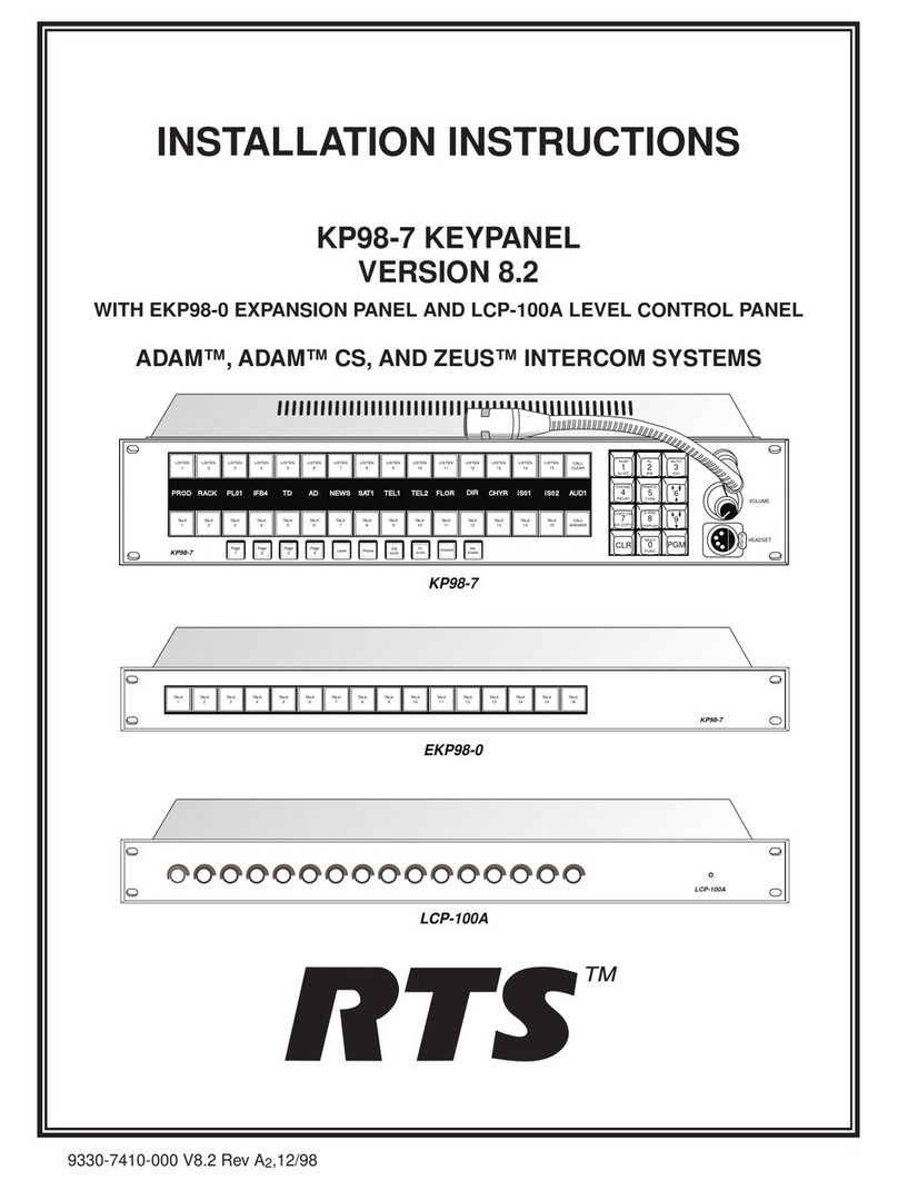
RTS SSA-324 User manual

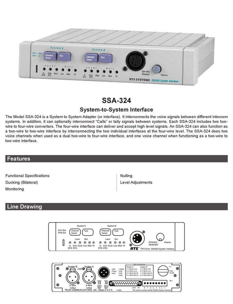
USER
MANUAL
MODELSSA324
System Interface
(System to System Adapter)
OQ
RTSTM
9350
-
6979
-
00
Rev
F
6/00

PROPRIETARY NOTICE
Theinformation and design disclosed herein were
originated by and are the property of RTS Systems. RTS
Systemsreservesall patent, proprietary design,
manufacturing,reproduction,use and salesrightsthereto,
and to any articledisclosedtherein, except to the extent
rights are expresslygranted to others.
COPYRIGHT NOTICE
Copyright 1993by RTS Systems. All rights reserved.
Reproduction in whole
or
in part withoutprior written
permission from RTS Systems is prohibited.
PATENT NOTICE
This equipment contains and uses a design embodiedin
United StatesPatent No. 4,358,644: “A Bilateral Current
Sourcefor a Multi
-
terminalIntercom”. This design
employs a two
-
wire to four
-
wire converter.
UNPACKING AND INSPECTION
Immediatelyupon receipt of the equipment, inspect the
shippingcontainer and the contents carefullyfor any
discrepancies
or
damage. Should there
be
any,notify the
freightcompany and the dealerat once.
WARRANTY INFORMATION
Theproducts of RTS Systems are warranted to
be
free
from defects in materialsand workmanshipfor a period
of
three years from the date of sale.
RTS Systems soleobligationduring the warranty period
is toprovide, withoutcharge,parts and labor necessary to
remedy covered defectsappearing in productsreturned
prepaid to RTS Systems. This warranty does not cover
any defect, malfunctionor failure caused beyond the
control of RTS Systems,including unreasonable
or
negligent operation,abuse, accident, failureto follow
instructionsin the ServiceManual or the User Manual,
defective
or
improperassociated equipment, attemptsat
modification and repair not authorized by RTS Systems,
and shippingdamage. Products with their serial numbers
removed
or
effaced arenot covered by this warranty.
To
obtain warranty service,follow the proceduresentitled
“ProcedureFor Returns” and “ShippingtoManufacturer
forRepair
or
Adjustment”.
This warranty
is
the soleand exclusiveexpresswarranty
given with respect to RTS Systems.products. It is the
responsibility of the user
to
detemune before purchase
that this product is suitableforthe user’s intended
purpose.
ANY ANDALLIMPLIEDWARRANTIES,
INCLUDING THE
IMPLIED
WARRANTY OF
MERCHANTABILITYARE LIMITEDTOTHE
DURATIONOF
THIS
EXPRESS
LIMITED
WARRANTY.
CUSTOMER SUPPORT
Technicalquestions should be directed to:
Customer ServiceDepartment
RTSRelex
12000Portland Avenue South
Burnsville, MN 55337 U.S.A.
Telephone: (952) 884
-
405
1
Fax: (800) 323
-
0498
RETURNSHIPPING INSTRUCTIONS
PROCEDURE FOR RETURNS
If a repair is necessary, contact the dealer where this unit
was purchased.
If repair throughthe dealer is not possible, obtain a
RETURN AUTHORIZATIONfrom:
Customer ServiceDepartment
Telex Communications,Inc.
Telephone: (877) 863
-
4169
Fax:
(800)
323
-
0498
DONOT RETURNANY EQUIPMENT DIRECTLY
TOTHEFACTORY WITHOUT
FIRST
OBTAINING A RETURN AUTHORIZATION.
Be prepared to provide the company name, address,
phone number, a person to contactregarding the repair,
the type and quantity of equipment,a descriptionof the
problemand the serial number(s).
SHIPPINGTOMANUFACTURERFOR REPAIR OR
ADJUSTMENT
All shipmentsof RTS Systemsequipment should
be
made
via United Parcel Service
or
the best availableshipper,
prepaid. The equipment should
be
shipped in the original
packing carton; if that is not available,use any suitable
containerthat
is
rigid and
of
adequate size. If a substitute
containeris used, the equipment should
be
wrapped in
paper and surroundedwith at leastfour inches
of
excelsior
or
similar shock
-
absorbingmaterial. All
shipmentsmust be sentto the following address and must
includethe Return Authorization.
CustomerServiceDepartment
Telex Communications,Incorporated
West 1stStreet
Blue Earth, MN 56013 U.S.A.
Upon completion of any repair the equipmentwill
be
returned via United Parcel Serviceor specifiedshipper
collect.
NEITHER RTS SYSTEMSNOR
THE
DEALER
WHO
SELLSRTS SYSTEMSPRODUCTS
IS
LIABLE FOR
INCIDENTAL
OR
CONSEQUENTIALDAMAGES OF
ANY KIND.
2
SSA324
User
Manual
.
.
.
TABLE
OF
CONTENTS
PROPRiETARYNO
TI.
....................................................
2
COPYRIGHTNOTICE
.....................................................
2
PATENT NO^
.........................................................
2
UNPACKINGANDINSP~ON
...............................................
2
WARRANTYINFORMATlON
.................................................
2
FtETURNSHIPPINGINSTRUCTIONS
............................................
2
SECTION
1;
DESCRIPTION
AND
SPECIFICATIONS
..................................
5
1.1DEs~ON
.......................................................
5
1.2SPEclFICATIONS
.....................................................
5
1.2.1 FWNCTIONAL SPECIFICATIONS
..........................................
5
1.2.2 ETJXTRICAL SPECIFICATIONS
.........................................
7
SECTION
2:
INSTALLATION
................................................
9
2.1 MECHANICALINSTALLATION
.............................................
9
22 ELECTRICALINSTALLATION
.............................................
9
SECTION
3:
OPERATION
..................................................
11
3.1 CONTROLS AND CONNECTORS
............................................
11
3.20PEWTION
........................................................
11
3.2.1-G
......................................................
11
3.2.2 LEVELSFITING
..................................................
11
3.2.3DUCKSE~G
...................................................
11
SECTION
7:
DIAGRAMS
..................................................
12

TB1-1.2 UlOlA RlO5 UlMA UlOlB U103B U103A U104A
u105
T105
JlOl
TB1-5.6 U201A
R205
U2MA U201B U203B U203A U204A u205
"
205
J102
Four
IVVtfEit
Zin=
A~lldB Adjust uitry A~l0dB F~=200Hz
F-5
kHz AMdB
Source
former
Output
25k
NOm
LevelTo Two
Uuck Buffer Low
Pass
Buffer Bilateral
Optional
Wire
Current
-
Trans
-
-D
Diffl
Amp
RTS
(2
-
W)
-
Circ
-
Amp
-
-
Filter
-
Amp
-
*-5
*dt
JlOl
SlOl
S105
W103
T105
U104 B
u106
u102c
J201 S2Ol S205 W203
"
205
U204 B u206 u2mc
Two
Wire Balanced/ Channel Gnnmd
Optional
Differential
Null
Duck
Input -Unbalanced
-
Select
-
Reference
%=IO
k
Switch Switch Jmper fonner
Amplifier
Circuitry Ciatitry
Nominal
-
Trans
-
-Input Buffer
-
-
-
-
UlO7A
S
103
R145
.
U207A s203 R245
~
I
Buffed Test Level
From
11
dB Pickoff Adjust
-
Amplifer
-
Switch
-
RTS (2 Wire)-
U107B u108 TIM
U207B u208
"202
TB1-7.8
TB1-3.4
Figure
1
-
1
SSA324
Block
Diagram
System Interface(System
to
System Interface)

SECTION
1:
DESCRIPTIONAND SPECIFICATIONS
1.1 DESCRIPTION
(See!
Block
Diagram,
Figure
1
-
1)
TheModel
SSA324
is
a System
to
SystemAdapter (or inter-
face). It interconnects the voice signals between different
intercom systems.
In
addition,
it
can
optionally interconnect
“Calls”
or
taUy
signals between systems. Each
SSA324
in-
cludestwo
two
-
wire
to
four
-
wireconverters. The four-wire
interface can deliver
and
accept
high
level signals such
as
those
from
the Mccurdy intercom
system.
An
SSA324
can
alsofunction
as
atwo
-
wire
to
two-wireinterfaceby intercon-
necting the two individual interfaces at the
four
-
wire
level.
The
SSA324
des
two voice channelswhen
used
as
adual
two
-
wire
to
four-wireinterface,and onevoice channelwhen
functioning
as
a two-wireto two-wire interface.
A
front panel channel select switch for each
of
the two
interfaces (A and
B)
will
select one of two, two
-
wire chan-
nels. For ClearCom
use,
theswitchwill
be
in the Channel
2
position. For
Audiocom
use, a rear panel switch will select
balanced two
-
wire operation.
Front panel controls include
1)
adjustments for null, level,
ducking,
2)
switchesfor monitoring and channelselect.
Rear
panel controls include balance/unbalance switches for
the two
-
wire ~onne~tionof each interface.
Rear
panel con-
nectors include two
XLR3
connectors for two-wire, eight
0
terminals for two four-* interconections,
one
25
pin
D
connector for duplicate four-wire connections plus options
connections. The terminals
are
useful
forrapid fieldconnec-
tions. The
D
connector
aids
rapidreplacementwhere mean-
time
-
to
-
repair
is
an
issueand
also
allows option strapping.
The SSA324replacesthe Model
lWI224
and
1wI222
inter-
faces where powering
from
the
intercom
is not
required.
Differencesbetween the Model
lWI224
/
TWI222
interface
and Model
SSA324
include
the
following:
1)
The
SSA324
is
self
(locally) powered, the
TWI224
/
TWI222
is usually
powered
from
the
TW
lineormay
be
locally
powered.
2)
The
SSA324
has
a maximum output at
the
four-wire output port
of
+22
dBm, the
‘WE224
/
TWI222
maximum output is
9
dBm.
1.2SPECIFICATIONS
1.2.1 FUNCTIONAL SPECIFlCATIONS
The Model
SSA324
consists of two two
-
wire
to
four-wire
convertersin a singlepackage(converterAand converter
B).
If
the
two converters
are
interconnected,theModel SSA32A
then functions
as
two
-
wire
to
two-wire converter. The
method
of
interconnection
is
as
follows: converterA’s four-
@
wire
output
is
connected
to
converter
B’S
four-wire input;
converter A’s four-wire input
is
connected
to
converter
B’s
output.
Converter
A’s
two
-
wireport isdriven by an activebalanced
bilateral current
source
(an
optional transformer may be
added). Converter
B’s
two
-
wire
port
is
similarto Converter
A’S.
Converter
A’s
four-wireoutput
port
is
driven by an active
balanced voltageline driver (or
via
an optionaltransformer).
A
build-out resistor (about 33
ohms)
in
each
leg
of the
differential output maintains stability driving long cables.
Converter
B’s
four
-
wire output port
is
similar
to
converter
A’S.
The
optional bansformers can be
used
to
provide higher
common
mode voltage isolation between the four-wire sys-
tern@)and
the
two
-
wiresystems.
ConverterA’s four-wireinput
port
isactivebalanced, bridg-
ing, ten thousand ohmsimpedance. Converter
B’s
four
-
wire
input port
is
similar
to
converter
A‘s.
(An
optional
trans
-
former
is
availablefor the four-wireinput(s).
Adjustable,
0
to
30
dB.
Toggles
from
one
direction to the
other (threshold
is
factory
set).
There
is
one
adjustment for
interface
A
andone for interface
B.
Each interfacehas depth
level adjustment(front panel).
Monitwing
Uses
standardheadset. Front Panel has six pin female
XLR
type
headset connector.
Switchon frontpanel activatesthemonitoringfunction.
User
uses
headset microphone
or
abuilt
in
oscillator
to
adjust for
null in headsetearphones(orvia
a
built
-
in oscillatorwhich
is
jumper selectedby ajumpex on theprinted circuitboard).
Nulling
There
are
three
null adjustments
associated
with each
two
-
wire
port.
These
are
resistive (medium), capacitive (high),
and inductive(low)nulls. Medium, High, and Low refers
to
frequency
ranges;
medium
centersabout
1
kilohertz,high, 3
kilohertz,
low,300 hertz.
There
are
two level adjustments for interface
A
(to
-
from
two
-
wire) and two for interface
B
(to-from two
-
wire).
SSA324
User
Manual
5

Application
The Model
SSA324
applicationsincludethe following:
1.Interfaceaudio signalsbetween intercom systems
as
shown
in Table 1
-
1,below.
Table
1
-
1
Numberof ChannelsInterfacedwith the Madel
SSA324
by System
System
2
McCurdyl
Generic4W Audiocom ClearCom
RTSI;?WB
RTSDWU
RTS14WB
System
1
mlal
2x.Bal2liumd
2!iuM
2"lai-
2.
Interface
(using
optional plug
in
boards)
the following non
-
audio signals:
Audiocom
call
signal to Audiocom callsignal.
RTS
Systems
call
signal
to
RTS Systemscall signal.
RTS
Systems
call
signal
to
form
C
relay
contact transfer.
Audiocom
call
signalto
form
C
relay
contact transfer.
Contact closure
to
RTS Systems
call
signal generation.
Contactclosure
to
Audiocom
call
signalgeneration.
ClearCom
to
RTS
Systemscall and viceversa.

e
1.2.1
ELECTRICALSPECIFICATIONS
(Specifications
at
120VAClinevoltage)
IndividualInterface Specification
(each
of'
two
dividual interfaces)
Two
-
WireInput
Impedance:5,000
ohms
+la%,
-
20% singleended,
10,000
ohms
+loo%,
-
20%differential
OperatingLevels
-
20dBu
to
+O
dBu,nominal
Two
-
WireOutput
Impedance:5,000
ohms
20%
singleended,
10.000
ohms
20%d&erential
OperatingLevelxO.1
mA
to
10
mA,
nominal
Four
-
WireInput
Impedance:lO,oOO
ohms
minimum singleended,
20,000
ohms
minimum
differential
operatingLevels:-lO dBu
to
+8
dBu,nominal
Four
-
WireOutput
Impedance:ohms singleended
or
differential
OperatingLevels-10dBu
to
+
8
dBu,nominal
0
TrierFundions
(Duck
Level setto
no
ducking)
Voltage
Gain,
Four
-
Wire In toTwo
-
Wire
Out*
Level Pot
1Wo
r0tation:O
3
dB
LevelPot
50%
rotation:-15
dB
4
dB
Transfer
Fun&=
(Duck
Level
set
to
no
ducking)
Voltage
Gain,
Two-WireIn
to
Four
-
WireOut**
LevelPot 100%mtation:22
dB
3dB
LevelPot
5090
rotation:8
dB
4
dB
Frequency
Response
(Reference:
1
kilohertz,
0
dBu input)
Four
-
WireInputto
Two
-
Wire Output:200 hertz
to
5
kilohertz,+1,-4
dB,
typical
Two-WaeInput to
Four Wire Output:250hertz
to
5
kilohertz,+1,
-
4
dB,typical
Sinal
-
to
-
Noise
Ratio
(Reference:
1
kilohertz,
0
dBu at two
-
wire)
TWO-WW
to
Four-Wire:
-
60
dB
F0ur-W~
to
Two-Wire:
-
60
dB
Crosstalk
(Reference:
1
kilohertz,
0
dBu)
System
A
to
System
B,
Two
-
wire
to
Twewire
200
hertz
to
5
kilohertz:
-
50
dB,
Environmental
Temperature
0perating:OO
to
50
"
Celsius
Storage:-40"
to
85"
Celsius
Humidity:O
to
95%. non
-
condensing
Mains
Voltage
Standard:120volts
10%,
50
-
60
hertz
*POpti0n:230volts 10%,
50
-
60
hertz
#D
Optiox100volts
+
10%.
-5%,
50
-
60
hertz
Mains
Amperes
Standar&O.UIA
@
120
volts
lo%,
50
-
60
hertz
*P
Option:O.lOA
@
230volts 10%.
50
-
60
hem
#D
OptioxO.22.A
@
100
volts
+
1w0.-5%.
50
-
60
hertz
Dimensions
Height
1.72
inches
(
44
millimeters)
Width.8.19 inches
(208
millimeters)
Depk8.00inches
(204
millimeters)
Weight
SSA324***:5.0
pounds
(2.3
kilograms)
MCP1:l.O
pounds
(0.45
kilograms)
MCp2.1.0 pounds
(0.45
kilograms)
FmishThermoplasticfrontpanel, aluminumcase, lightgray
finish.
0
Notes:
*
Where two
-
wireoutputvoltage
is
outputcurrenttimes terminationimpedance,
and
termination
impedance
is
200
ohms
33nF.
**
Nullpots setformaximumnull, 200
ohm
33nFnominal two
-
wireline.
***
SSA324
weight with optionaltransformers
in
place.

Figure
2
-
1
Rear
Panel,
Model
SSA324
SystemInterface
8
SSMM
user

SECTION
2:
INSTALLATION
0
2.1
MECHANICAL INSTALLATION
-
The Model
SSA324
can
be
installed in
3
ways: a singleunit
mounted
in
a
half
rack
space
using
an
optionalModel
M82
Kit forrack mounting
a
singleunit;
or
two
SSA324
supplies
mounted side by sideusing the optional
M81
Kit for rack
mounting two
units
side by side; or
free
standing using the
optional MCF% Kit for adding side channels for non-rack
mounting portable
use.
2.2
ELECTRICAL INSTALLATION
The connectionfor the headset
used
to
set
-
up
the
interface
is
on
the
frontpanel,
all
otherconnections
are
on
the
rear
panel.
Figure
2
-
1
shows
the
rear
panel connections. System
A
two
-
wire connection is
at
J101,
System
B,
5102.
These are
XLR-3-31
(female)
type
connectors. System
A
and
B
four-
wireconnectionsareatbothTBlandJ103.
J103alsocontains
connections
to
theoption card,when installed.
Low
voltage
alternatingcurrentpower isapplied to
J104
(16
volts,AC).
connector
Pin-outs
are
listed below.
Audimm
ClearCom
RTS RTS
1
**
*
CHI
23 3
23
2
CH2
-
3
Com
1
1
1
1
*S101
(System
B)
and/or
S102
(System
A)
set
to
in position
forbalanced operation.
**
If option
board
installedandCleaKomcalllightoperation
is
required,
move jumper
W103
(System A) and/or jumper
W203
(System
B)
on motherboard
to
23
position.
Jumper
J103- 7,20
for System
A,
and/or
J103- 12,25
forSystem
B.
System
A
System
B
TB
1-
TB
1-
Audio
In
Hi
1
5
Audio In
Lo
2
6
Audio Out
Hi
3 7
Audio Out
Lo
4
8
Earth
1
16VAC
2
16VAC
3
NoConn.
4
1
2
15
3
16
4
17
5
18
6
19
7
20
8
9
21
22
23
10
11
24
12
25
Earth
4-Wh
Audio
In
Hi,
System A
4
-
Wire
Audio In
Lo,
SystemA
4
-
Wire
Audio Out
Hi,
System A
4
-
Wire
Audio Out
Lo,
System A
4
-
Wire
Audio
In
Hi,
System
B
4
-
Wire
Audio In
Lo,
System
B
4
-
Wire
AudioOut
Hi,
System
B
4
-
Wire
Audio Out
Lo,
System
B
Call
SendGND
(A)
Call Send
Hi
(A)
DC
CallSig
En
GND
(A)
DCCaUSigEnHi(A)
Relay Contact NO
(A)
Relay ContactCOM
(A)
Relay Contact NC
(A)
Relay ContactNO
(B)
Relay Contact COM
(B)
Relay ContactNC
(B)
Call Send GND
(B)
Call Send
Hi
(B)
DCCallSigEnGND(B)
DCCallSigEnHi(B)
1
Mic
Lo
2
Mic
Hi
3
Headphone Com
4
Left
Headphone
Hi
5
Right
Headphone
Hi
6
No Connection
Place jimper on
~2
for tone test signal,
~3
for voice test
signal. Test signal
used
with headsetand
front
panel nulling
adjustments
to
null
return
two-wire signal.
e
-

I
Figure
3
-
1
SSA324
Front
Panel
10
SSMN
User
~anual

SECTION
3:
OPERATION
e
3.1
CONTROLS AND CONNECTORS
Front
Panel
switches
1. Channel Selectswitch,
CHl
out
/
CH2
in,
Sys.
A.
2.
Press
momentary switch fornulling System
A
3.
Channel Selectswitch,
CH1
out
/
CH2
in,
Sys.
B.
4.
Press
momentary switch fornulling System
B
Two
-
wire.
Two
-
wire.
connectnrs
5.
XLR6-3
1Female
6
pin headset
connector
@YN
MIC HEADSET)
Contmls
6.
Monitor headphone level
(VOLUME).
Indicator
7.
Indicator(Power)
Green
LED.
ay
LEVEL
TO
RTS,
System
A.
-
9.
LEVEL
FR
O
M
RTS, system
A
.
10.
DUCK Level, System
A.
11.
Inductive
(LOW)
null, System
A.
12.
Resistive
(MEDium)
null, System
A.
13. Capacitive(HIgh)null, System
A.
14.
LEVEL
TORTS,System
B.
15.
LEVEL
FROM
RTS
wire,
System
B.
16.
DUCK Level, System
B.
17.
Inductive
(Low)
null, System
B.
18.
Resistive
mum)
null, System
B.
19.
Capacitive(HIgh)null, System
B.
Rear
Panel
Switches
3.2
OPERATION
3.2.1
NULLING
PresetControls
as
Follows:
ToJFrom
RTS
SettoMidway
Duck Level Set
to
CW
LOW
Set
to
Midway
Med Setto Midway
Hi
Setto CCW
Volume
10
O’clock
Press
Test Switch
If
test signal tone, adjust Med for null, then
Hi,
then Low.
If test signal voice, say
ahhh
into
microphone,adjustMed
for
null,
then
Hi,
then Low.
ReleaseTestSwitch
3.2.2
LEVEL SETTING
Have Talkers
1
and
2
on Four-Wire System,Talkers
3
and
4
onTwo
-
WireSystem. AdjustTo/FromRTS Controls
so
that
all Talkers
can
hear other
at
about the samelevel regardless
of which system the
other
talkers
may
be
on.
3.23
DUCK SETTING
QukI&Yd
AdjustDuckLevelonlyif fullduplex
opemtion
is
notpossible
becauseof feedback. Adjust Duck Level carefullyfrom
CW
towanis CCW. Onlya
very
small
amount
of ducking should
beUSed.
20.
Unbalance(Out) Balance
(In)
/
SelectTwo-Wire,
21.
.
Unbalance
(Out)
Balance (In)
/
SelectTwo-Wire,
System
A
System
B
ssA324
user Manual
11

SECTION
7:
DIAGRAMS
SD6926
B
SchematicDiagram
-
System
To
System Adapter,Model SSA324,
Sht
1
of
3
SD6926
B
SchematicDiagram
-
System
To
SystemAdapter, Model SSA324,
Sht
2
of
3
SD6926
B
SchematicDiagram
-
System
To
System Adapter,Model
SSA324,
Sht
3
of
3
AS6926
B
AssemblyDiagram,PCA, System
To
System Adapter,Model SSA324
12
SSA324User Manual
Other manuals for SSA-324
2
Table of contents
Other RTS Intercom System manuals