5
INTRODUCTION
This manual describes the installation, programming, and
operating procedures for the RTS Model TIF 2000A Digital
Hybrid Telephone Line Interface. Since TIF 2000A
functions as a keypanel, the user may also need to refer to
the manuals and/or on-line help files for AZedit for infor-
mation on configuring certain features.
INSTALLATION
Rear Panel DIP Switch (S201)
The rear panel DIP switch contains switches to configure
the most often changed options. These include: auto answer
on/off, ring signal on/off, password on/off, intercom port
address, and full duplex method.
Auto Answer
Turning on the auto answer option will set the unit to
answer the phone automatically when it rings. The number
of rings required before it answers is determined by the
setting of internal DIP switch (S202). If auto answer is
turned off, the line will ring until someone at a keypanel
answers the call or until the Select button on the
TIF 2000A’s front panel is pressed. To turn ON auto answer,
place switch 1 in the down position. To turn OFF auto
answer, place switch 1 in the up position.
Generate Ring Signal
Turning on the generate ring signal option sets the unit so
that when the phone line is ringing, keypanels that are
configured to receive ring signals will produce an audible
ring. To turn ON the ring signal, place switch 2 in the down
position. To turn OFF the ring signal, place switch 2 in the
up position.
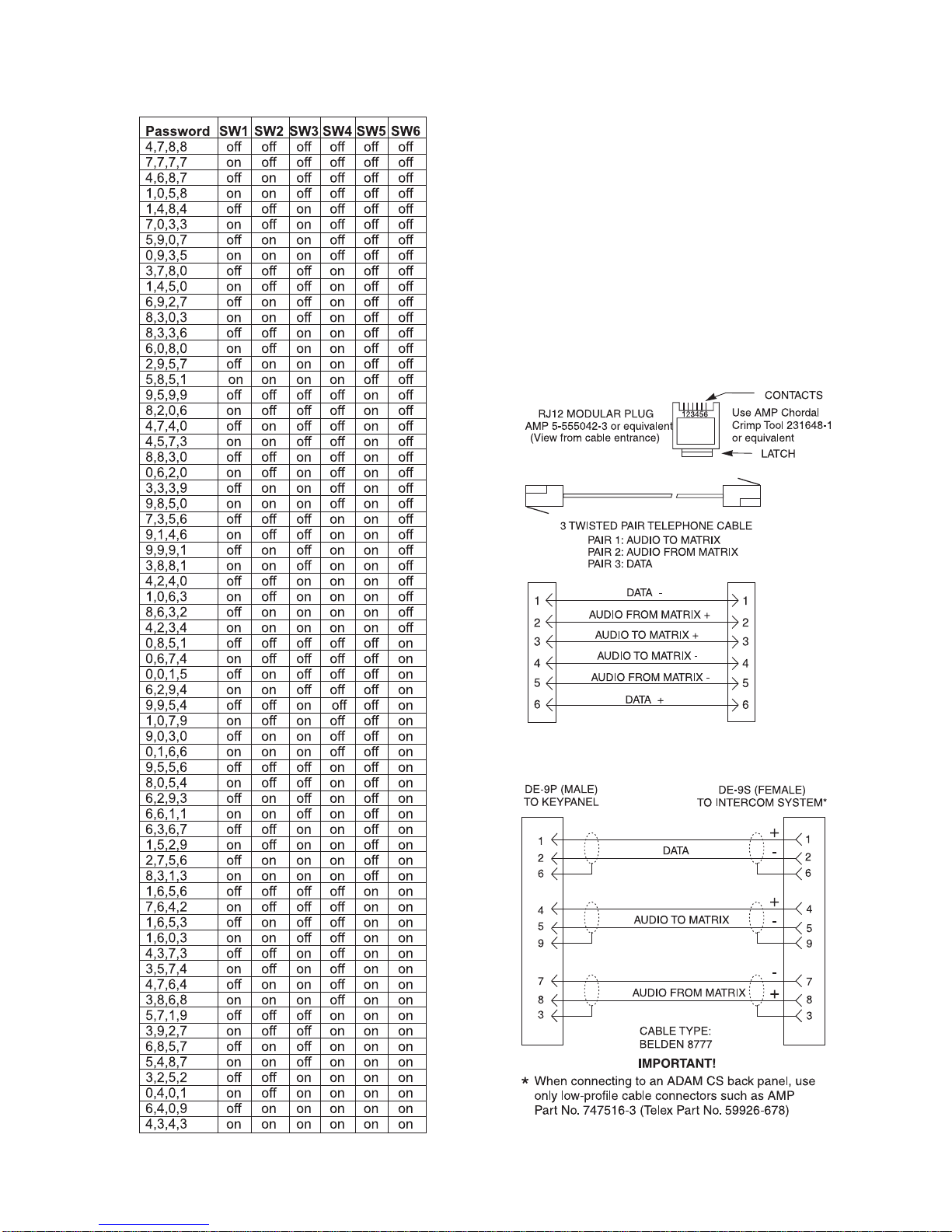
Password Required
Turning on the password required option sets the unit so that
when a call is automatically answered, the user must enter a
password via DTMF before the unit will allow communica-
tions. The password numeric sequence and length are
determined by the settings of internal DIP switch (S203). To
turn ON the password required option, place switch 3 in the
down position. To turn OFF the password required option,
place switch 3 in the up position.
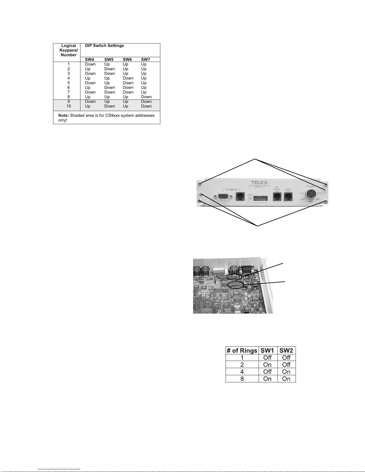
Intercom Port Address
Switches 4 to 7 determine the address of the unit. The port
address is expressed in binary with switch 4 being the least
significant bit (LSB) and switch 7 being the most significant
bit (MSB). To turn ON (set bit to 1), place the desired
switch in the down position. To turn OFF (set bit to 0), place
the desired switch in the up position. ADAM, ADAM CS,
and Zeus units use a 1-8 address scheme for their ports (e.g.
ports 1-8 have addresses 1-8, ports 9-16 have addresses 1-8,
etc...). CS 9xxx systems use a 1-10 scheme for port ad-
dresses (e.g. ports 1-10 have addresses 1-10, ports 11-20
have addresses 1-10, etc...).
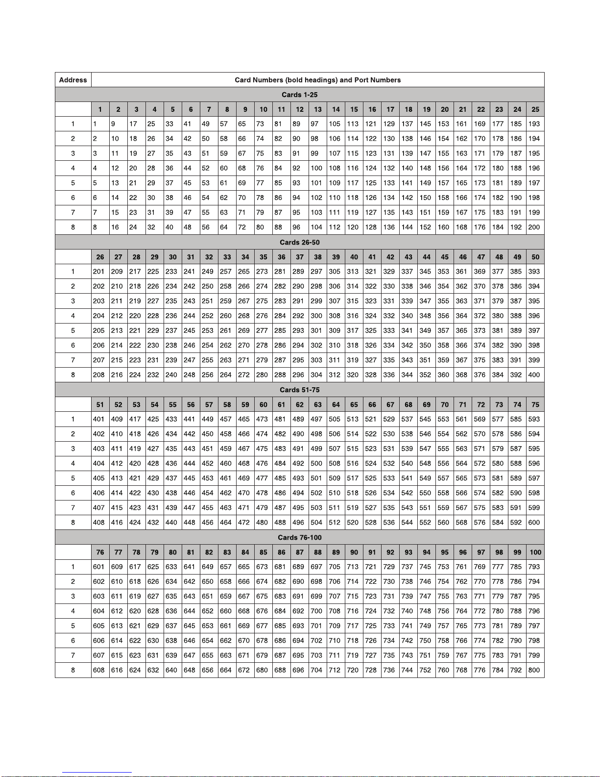
To set the address for ADAM, ADAM CS, or Zeus systems
do the following:
1. Determine the port number that will be used for the
TIF 2000A.
2. Locate the port number and its corresponding address in
Table 1.
Power
Indicator
Seizes &
Drops Line
Line Mode
Indicator
Audio to Matrix
Level Adjustment Audio to Telephone Line
Level Adjustment
Audio to Matrix
Level Meter Audio to Telephone Line
Level Meter
Intercom Matrix
Connections Data Present Address &
Configuration Telephone Line
Connections Power
Rear Panel Features
Figure 2 - TIF 2000A Rear Panel Features
Important! Be sure to review any recently added
supplemental information before proceeding.
Supplements are placed at the back of the manual.
DESCRIPTION
The TIF 2000A is a single line digital hybrid telephone line
interface designed to be compatible with ADAM,
ADAM CS, ZEUS, and CS 9000 series intercom systems. It
provides bi-directional communication between the inter-
com matrix and a standard DTMF capable telephone line. It
allows the phone to access all crosspoints of the matrix, as
well as dynamic party lines, IFB circuits, and other forms of
communications. The 1U high by ½ wide rack mountable
(via an optional kit) TIF 2000A provides a transparent link
to the telephone system enabling full dial-out capability
from any designated keypanel with keypad. The TIF 2000A
has full dial-in capability giving the caller a keypanel on the
system via commands from the DTMF pad on their tele-
phone. Since the TIF 2000A appears to the matrix as any
other keypanel would, the only limitation on the number of
units in the system is the same as for other keypanels.
Front Panel Features
Figure 1 - TIF 2000A Front Panel Features