RTX 2300 User manual

User’s Manual V1.00 RTX2300 – Smart ATE 1
RTX2300
Smart ATE
User Manual
Version: 1.00

User’s Manual V1.00 RTX2300 – Smart ATE 2
General
Information contained in this document is subject to change without notice. RTX A/S makes
no warranty of any kind regarding this material, including, but not limited to, the implied
warranties of merchantability and fitness for a particular purpose. RTX A/S shall not be
liable for errors contained herein or for incidental or consequential damages about the
furnishings, performance, or use of this material.
Warranty
This instrument is warranted against defects in material and Workman ship for a period of
one year from date of shipment. During the warranty period, RTX A/S will at its option,
either repair or replace products, which prove to be defective. For warranty service or
repair, this product must be returned to a service facility designated by RTX A/S. Buyer
shall prepay shipping charges to RTX A/S and RTX A/S shall pay shipping charges, duties,
and taxes for products returned to RTX A/S from another country. RTX A/S warrants that
its software and firmware designated by RTX A/S for use with an instrument will execute
its programming instructions when properly installed on that instrument. RTX A/S does not
warrant that the operation of the instrument or firmware will be uninterrupted or error
free.
Limitation of Warranty
The foregoing warranty shall not apply to defects resulting from improper or inadequate
maintenance by Buyer, Buyer-supplied software or interfacing, unauthorized modification
or misuse, operation outside of the environmental specifications for the product, or im-
proper site preparation or maintenance.
NO OTHER WARRANTY IS EXPRESSED OR IMPLIED.RTX A/S SPECIFICALLY DISCLAIMS
THE IMPLIED WARRANTIES OF MERCHANTABILITY AND FITNESS FOR A PARTICULAR
PURPOSE.

User’s Manual V1.00 RTX2300 – Smart ATE 3
General information
This document and the information contained, is property of RTX A/S, Denmark.
Unauthorized copying is not allowed. The information in this document is believed to be
correct at the time of writing. RTX A/S reserves the right at any time to change said
content, circuitry and specifications.
The general safety precautions, according to the information provided in the RTX2300
User’s Manual, must be observed during all phases of operation. RTX A/S assumes no
liability for the customer’s failure to comply with these requirements.
The purpose of the document is to provide guidance to users of the RTX2300 Smart ATE.
The User’s manual describes general functions of the test equipment and describes the use
of the related Windows® based interface, as well as interfacing with a production
application program.

User’s Manual V1.00 RTX2300 – Smart ATE 4
Safety information
The following general safety precautions must be observed during all phases of operation
and service of this instrument. Failure to comply with these precautions or with specific
warnings elsewhere in this manual violates safety standards of design, manufacture, and
intended use of the instrument. RTX A/S assumes no liability for the customer’s failure to
comply with these requirements.
DO NOT operate the product in an explosive atmosphere or in the pre-
sence of flammable gasses or fumes.
DO NOT use repaired fuses or short-circuited fuse holders: For continued
protection against fire, replace the line fuse(s) only with fuse(s) of the
same voltage and current rating and type.
DO NOT perform procedures involving cover or shield removal unless
you are qualified to do so – it is therefore strongly emphasized here that
operating personnel must not remove equipment covers or shields.
Procedures involving the removal of covers and shields are for use by
service-trained personnel at RTX A/S only.

User’s Manual V1.00 RTX2300 – Smart ATE 5
Electrostatic Discharge
Electrostatic discharge (ESD) can damage electronic test equipment. Working with
electronic components or test equipment should always be performed at a static-safe place.
High Voltage
Some power supplies can generate high voltage, which can damage the all the port of the
unit. To prevent damage to the RTX2300 Smart ATE please make sure that the device is
properly earthed.

User’s Manual V1.00 RTX2300 – Smart ATE 6
Documentation information
This User’s Manual contains essential items of information needed for general-purpose use
of the test equipment along with a detailed description for high throughput production
purposes. In this document you will find valuable information on how to unpack, install and
operate your RTX2300 Smart ATE unit.
The User’s Manual provides programming guidance to users of the RTX2300 Smart ATE
who would like to write their own test programs. A few examples on how to use the DLL
function calls in your source code are also outlined. However, please note that the
examples and code fragments are included for informational reasons only and should only
be used as a guidance to ease test program development. It is therefore strongly
emphasized here that RTX takes no responsibility for debugging and verification of the
actual test program developed by the customer.
Conventions Used in this Manual
The following text conventions are used in this guide:
Parameter used to represent a parameter, value or data in an entry field
RUN used to represent the text in the Windows® based user interface
Abbreviations Used in this Manual
The following abbreviations are used in this guide:
API Application Programming Interface
ATE Automatic Test Equipment
CCB Customized Connector Block (physically the same as SCB but with
customized connectors)
DECT Digital Enhanced Cordless Telecommunications
DUT Device Under Test
GUI Graphical User Interface
LED Light Emitting Diode
PSU Power Supply Unit
QSK Quick-Swap Kit
REPS RTX EAI Port Server
RF Radio Frequency
SCB Standard Connector Block (PCB with 2 connectors – one 2x25 pin header
and 3x14 pin + 6RF option + 2 pneumatic)
SCPI Standard Commands for Programmable Instruments
SMPS Switch Mode Power Supply
THD Total Harmonic Distortion
DUT Devicenit Under Test

User’s Manual V1.00 RTX2300 – Smart ATE 7
CONTENT
1. GETTING STARTED .............................................................................................................................. 11
A. INTRODUCTION ........................................................................................................................................... 11
B. UNPACKING THE RTX2300 SMART ATE.......................................................................................................... 12
i. Initial Inspection ............................................................................................................................................ 12
ii. Box content.................................................................................................................................................... 12
C. GENERAL OVERVIEW OF THE RTX2300 SMART ATE UNIT................................................................................... 12
i. Rear Panel Connectors................................................................................................................................... 12
ii. Internal Connectors ....................................................................................................................................... 14
Shielded Fixture Bay Connectors......................................................................................................................... 14
Controller Chamber Connectors ......................................................................................................................... 16
iii. Front Panel Functions .................................................................................................................................... 17
D. OVERVIEW OF INSTRUMENTATION AND FUNCTIONAL BLOCKS................................................................................ 19
i. Digital AC & DC Voltmeter (DVM) .................................................................................................................. 20
ii. Tone Generator.............................................................................................................................................. 20
iii. Signal multiplexer .......................................................................................................................................... 20
iv. GPIO ............................................................................................................................................................... 20
v. Main functional blocks in the RTX2300.......................................................................................................... 21
Fixture and box control ....................................................................................................................................... 21
Power supply....................................................................................................................................................... 21
Communication interfaces .................................................................................................................................. 22
Expansion slot USB interfaces........................................................................................................................ 22
RTX2300 control interface ............................................................................................................................. 22
CCB USB interface .......................................................................................................................................... 22
SCB USB interface .......................................................................................................................................... 22
DUT serial communication configuration ...................................................................................................... 22
E. INSTALLING RTX2300 OPTIONS ..................................................................................................................... 24
i. Installing modules.......................................................................................................................................... 24
ii. Installing Quick-Swap Kit................................................................................................................................ 25
Installing the fixture bay part of the Quick-Swap Kit........................................................................................... 25
Installing the fixture part of the Quick-Swap Kit ................................................................................................. 26
iii. Installing a fixture kit ..................................................................................................................................... 28
With QSK installed:................................................................................................................................................... 28
Without QSK installed: ............................................................................................................................................. 29
F. SYSTEM SETUP AND INSTALLATION OF THE RTX2300.......................................................................................... 30
i. Connecting the RTX2300 Smart ATE .............................................................................................................. 30
G. INSTALLING THE PC SOFTWARE ...................................................................................................................... 31
i. Installing the RTX2300 Basic Unit SW ............................................................................................................ 33
ii. Installing the RTX2300 USB Bridge Driver ...................................................................................................... 36
iii. Installing the RTX EAI Port Server .................................................................................................................. 37
iv. Installing the RTX2300 DUT UART driver ....................................................................................................... 39
v. Installing the RTX2300 Basic Unit Communication driver.............................................................................. 41
2. RTX2300 BASIC UNIT SW PACKAGE ..................................................................................................... 43
A. INTRODUCTION ........................................................................................................................................... 43
B. CONTENTS OF THE RTX2300 BASIC UNIT SW PACKAGE ..................................................................................... 43
i. Windows applications.................................................................................................................................... 43
ii. Documentation .............................................................................................................................................. 44
iii. Source Code and Binaries .............................................................................................................................. 44
C. RTX EAI PORT SERVER ................................................................................................................................. 44
i. Setup - General Page Overview ..................................................................................................................... 45
ii. Setup - UART Page Overview ......................................................................................................................... 46
iii. Setup – Socket Page Overview....................................................................................................................... 47
iv. Status Window Overview............................................................................................................................... 48
D. RTX2300 DETECTIVE DEBUG APPLICATION....................................................................................................... 48
i. I/O Page Overview ......................................................................................................................................... 48
Output pane ........................................................................................................................................................ 51
Input pane........................................................................................................................................................... 52

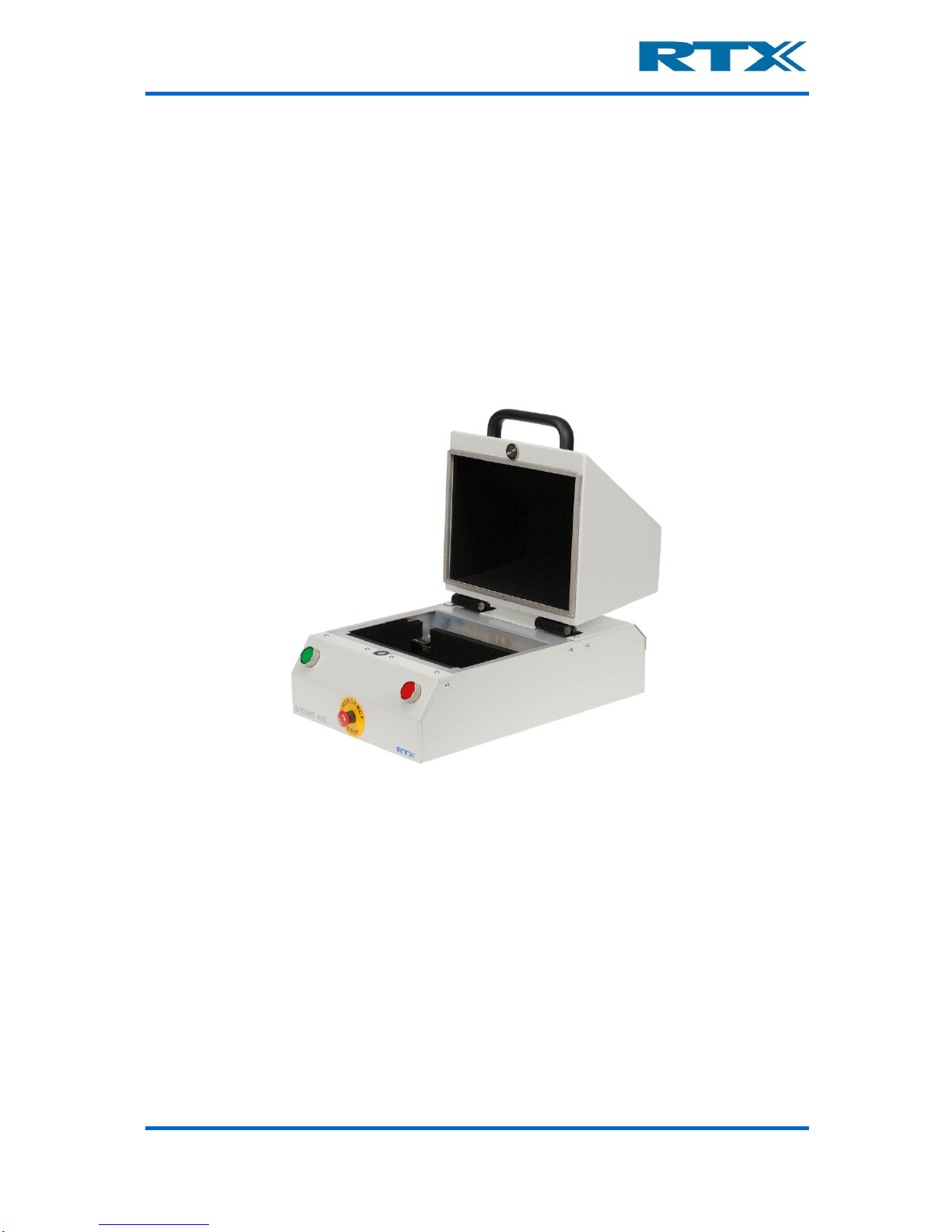
User’s Manual V1.00 RTX2300 – Smart ATE 8
ii. Ad/Da Page Overview .................................................................................................................................... 52
DAC...................................................................................................................................................................... 53
ADC...................................................................................................................................................................... 54
iii. Audio Page Overview..................................................................................................................................... 54
Level .................................................................................................................................................................... 55
Distortion ............................................................................................................................................................ 55
Generator............................................................................................................................................................ 56
iv. PWM Page Overview ..................................................................................................................................... 56
v. DUT Page Overview ....................................................................................................................................... 57
SCB bus................................................................................................................................................................ 58
USB enable .......................................................................................................................................................... 58
DUT SerCom ........................................................................................................................................................ 58
vi. Power Supply Page Overview ........................................................................................................................ 58
Voltage ................................................................................................................................................................ 58
Current ................................................................................................................................................................ 58
Current range ...................................................................................................................................................... 59
PSU Selection ...................................................................................................................................................... 59
Measurements .................................................................................................................................................... 59
vii. General Page Overview.................................................................................................................................. 60
Status .................................................................................................................................................................. 61
Access Mode ....................................................................................................................................................... 61
viii. Info Page Overview ........................................................................................................................................ 61
Serial number...................................................................................................................................................... 63
Insert/CCB Info.................................................................................................................................................... 64
ix. Firmware Page Overview ............................................................................................................................... 65
Firmware information ......................................................................................................................................... 66
Firmware update................................................................................................................................................. 66
x. User Data Page Overview............................................................................................................................... 67
xi. Logs Page Overview ....................................................................................................................................... 68
Logs ..................................................................................................................................................................... 68
Errors................................................................................................................................................................... 68
xii. Settings Page Overview.................................................................................................................................. 69
3. USING THE RTX2300 WINDOWS SW.................................................................................................... 70
A. INTRODUCTION ........................................................................................................................................... 70
B. USING THE RTX2300 DETECTIVE DEBUG APPLICATION ....................................................................................... 70
i. Configuring the RTX EAI Port Server (REPS) ................................................................................................... 70
ii. Launching and use of the RTX2300 Detective application ............................................................................. 74
Launching RTX2300 Detective............................................................................................................................. 74
Using the RTX2300 Detective application for debugging purposes .................................................................... 76
C. PERFORMING UNIT TESTS WITH THE RTX2300.................................................................................................. 77
4. RTX2300 SMART ATE OPTIONS ........................................................................................................... 81
A. MODULES .................................................................................................................................................. 81
i. Programmable PSU Module........................................................................................................................... 82
ii. Frequency Counter Module ........................................................................................................................... 82
Standard Frequency Counter .............................................................................................................................. 83
High-Stabilty Frequency Counter ........................................................................................................................ 83
B. QUICK-SWAP KIT (QSK) ............................................................................................................................... 83
i. Fixture bay part.............................................................................................................................................. 83
ii. Fixture part .................................................................................................................................................... 84
C. FIXTURE KITS .............................................................................................................................................. 84
i. Standard Fixture Kit with pneumatic slide ..................................................................................................... 84
ii. Standard Fixture Kit without pneumatic slide................................................................................................ 85
D. CONNECTIVITY OPTIONS ................................................................................................................................ 85
i. DUT Interface................................................................................................................................................. 85
SPI interface to DUT ............................................................................................................................................ 85
I2C interface to DUT ............................................................................................................................................ 86
ii. Rear panel...................................................................................................................................................... 86
RJ45 connection .................................................................................................................................................. 86

User’s Manual V1.00 RTX2300 – Smart ATE 9
5. FIXTURE BAY CONNECTOR INTERFACES............................................................................................... 87
A. STANDARD FIXTURE BAY CONNECTORS ............................................................................................................ 88
i. SCB ................................................................................................................................................................. 89
ii. CCB................................................................................................................................................................. 89
B. QUICK-SWAP KIT CONNECTORS –FIXTURE BAY PART (OPTION) ............................................................................ 89
i. SCB ................................................................................................................................................................. 90
ii. CCB................................................................................................................................................................. 91
C. QUICK-SWAP KIT CONNECTORS –FIXTURE PART (OPTION) .................................................................................. 91
i. SCB ................................................................................................................................................................. 93
ii. CCB................................................................................................................................................................. 93
D. SCB INTERFACE PIN OVERVIEW ...................................................................................................................... 94
E. CCB INTERFACE PIN OVERVIEW...................................................................................................................... 97
F. ELECTRICAL CHARACTERISTICS FOR FIXTURE INTERFACES.................................................................................... 100
6. RTX2300 CUSTOMIZATION................................................................................................................ 102
A. CONTROLLER CHAMBER CUSTOMIZATION INTERFACE........................................................................................ 102
B. CUSTOMIZATION INTERFACE PIN OVERVIEW ................................................................................................... 103
i. Customization Output Connector Pin Overview (J402) ............................................................................... 104
ii. Customization Input Connector Pin Overview (J400) .................................................................................. 106
iii. Customization Input Connector Pin Overview (J401) .................................................................................. 108
iv. Customization Input Connector Pin Overview (J403) .................................................................................. 110
v. External AUX Interface Connector (J1205)................................................................................................... 112
C. CREATING A CUSTOMIZATION BOARD FOR THE RTX2300 .................................................................................. 113
i. Customization board - dimensions and connector types............................................................................. 114
Board dimensions and connector location........................................................................................................ 114
Connector types ................................................................................................................................................ 114
ii. Reference PADS file ..................................................................................................................................... 115
D. CUSTOMIZATION OF FIXTURES FOR THE RTX2300............................................................................................ 115
7. IMPLEMENTING RTX2300 TEST PROGRAMS ...................................................................................... 118
A. RTX2300 API OVERVIEW ........................................................................................................................... 118
B. HOW TO IMPLEMENT A RTX2300 TEST PROGRAM ........................................................................................... 120
i. Example 1 – simple test program................................................................................................................. 120
ii. Example 2 – test program controlling multiple RTX2300 units.................................................................... 122
iii. Example 3 – firmware update program ....................................................................................................... 124
C. DYNAMIC LINK LIBRARY INTERFACING ............................................................................................................ 126
i. Dynamic Link Library Interface Description ................................................................................................. 126
Calling Convention ............................................................................................................................................ 126
Explicit DLL Linking ............................................................................................................................................ 127
Implicit DLL Linking............................................................................................................................................ 127
8. SPECIFICATIONS AND CHARACTERISTICS ........................................................................................... 128
A. INTRODUCTION ......................................................................................................................................... 128
B. RTX2300 SMART ATE BASIC UNIT ............................................................................................................... 128
i. D/A channels................................................................................................................................................ 128
ii. Tone generator ............................................................................................................................................ 128
iii. Audio buffer................................................................................................................................................. 129
iv. A/D channels................................................................................................................................................ 130
v. Audio measurement .................................................................................................................................... 131
vi. GPIO ............................................................................................................................................................. 132
vii. General Specifications.................................................................................................................................. 133
Power supply..................................................................................................................................................... 133
Mechanical specification................................................................................................................................... 133
Reliability requirements.................................................................................................................................... 133
Input/output connectors................................................................................................................................... 134
C. OPTIONAL MODULES.................................................................................................................................. 135
i. Programmable PSU ...................................................................................................................................... 135
ii. Frequency counter....................................................................................................................................... 136

User’s Manual V1.00 RTX2300 – Smart ATE 10
9. MAINTENANCE ................................................................................................................................. 137
A. INTRODUCTION ......................................................................................................................................... 137
B. GENERAL CUSTOMER RESPONSIBILITIES .......................................................................................................... 137
C. OPERATOR MAINTENANCE .......................................................................................................................... 137
i. General maintenance................................................................................................................................... 137
Replacing lid gasket........................................................................................................................................... 137
Replacing fuses.................................................................................................................................................. 138
Calibration of pneumatic pressure.................................................................................................................... 139
ii. Cleaning the RTX2300 unit........................................................................................................................... 139
D. CONTACTING RTX A/S OR RTX2300 DISTRIBUTORS ........................................................................................ 140
i. Before calling RTX A/S or the distributor ..................................................................................................... 140
ii. Check the Basics........................................................................................................................................... 140
iii. Sales and Service Office ............................................................................................................................... 141
E. RETURNING YOUR RTX2300 UNIT FOR SERVICE ............................................................................................. 142
i. Obtaining an RMA for service return ........................................................................................................... 142
ii. Packing the Unit for Shipment ..................................................................................................................... 143
APPENDIX A – EXAMPLE CODE – SIMPLE TEST PROGRAM (C++).................................................................. 144
APPENDIX B – EXAMPLE CODE – MULTIPLE RTX2300 UNITS (C++)............................................................... 146
APPENDIX C – EXAMPLE CODE – FIRMWARE UPDATE (C++)........................................................................ 149

User’s Manual V1.00 RTX2300 – Smart ATE 11
1. Getting Started
A. Introduction
The RTX2300 Smart ATE is a highly optimized automated test solution for calibration and
functional test in the production of wireless devices (including DECT, GSM, Wi-Fi, Blue-
tooth™, etc.). The design of the RTX2300 is based on extensive experience within devel-
opment and installation of Automated Test Equipment (ATE) systems, and hence, key
parameters as handling-time, flexibility and size have been considered as part of the design
process.
The RTX2300 Smart ATE is a multipurpose solution to simplify and cost-reduce the pro-
duction test environment dramatically compared to traditional “rack and stack” wireless
test implementations. The RTX2300 reduces the complexity and size of the ATE system
through the inclusion of modular instrumentation internal to the test unit, including a digital
volt meter, tone generator, and signal multiplexer. Optional internal instrumentation
includes a programmable power supply, and a frequency counter. These components allow
for the calibration and test of the baseband and audio portions of a Device Under Test
(DUT) without the need for additional external equipment.
The flexible nature of the RTX2300 Smart ATE enables a swift physical reconfiguration and
it can streamline the manufacturing process, since in literally a matter of seconds, it can
be physically reconfigured to accommodate different products and test types. The RF
shielded compartment of the RTX2300 can be customized with a device-specific probe
fixture, including a pneumatic capture unit to automatically hold the DUT in place during
test. Furthermore, the RTX2300 can decrease overall product test time since it has been
designed to allow several units to be set up in parallel, enabling optimal use of RF, base-
band, acoustic test resource, and effectively reducing the handling time of the DUTs.
The RTX2300 Smart ATE can be used for Printed Circuit Board (PCB) as well as final product
testing. It features a customization area that enables the interconnection between internal
and external measurement functionality and the DUT, hence reducing both space
requirements and complexity for the total test system. The flexibility of the RTX2300
simplifies the customization of the test platform, and enables economical replication. A
production test system can be implemented by using one or more RTX2300 Smart ATE
units in combination with an RF communication tester (such as the RTX2011/RTX2012 HS
DECT/DECT 6.0/CAT-iq RF Tester or Agilent 8960) and a PC for executing the test appli-
cation.

User’s Manual V1.00 RTX2300 – Smart ATE 12
B. Unpacking the RTX2300 Smart ATE
i. Initial Inspection
Please inspect the shipping container for damage. If the shipping container or packaging
material is damaged, it should be kept until the contents have been checked mechanically
and electrically. If any mechanical or electrical damage is observed, please notify RTX A/S.
Please refer to the description on how to contact RTX A/S provided in this document. Please
also keep the damaged shipping materials (if any) for inspection by the carrier and an RTX
A/S representative.
NOTE: The handle on the shield must not be used for lifting the RTX2300 out of the box.
ii. Box content
When unpacking the RTX2300 Smart ATE please verify that the items listed below are
included in the box:
•RTX2300 Smart ATE unit
•Power Supply
•USB cable (for communication between the RTX2300 unit and a PC)
•Optional items (modules, fixtures, QSK kit etc.) – if ordered
C. General overview of the RTX2300 Smart ATE Unit
The RTX2300 Smart ATE unit provides a wide range of external as well as internal con-
nectors. The connectors and functions can be divided into the following categories:
•Rear panel Connectors
•Internal Connectors
oShielded Fixture Bay Connectors
oController Chamber Connectors
•Front Panel Functions
Each of these categories will be descibed in more detail in the following.
i. Rear Panel Connectors
The RTX2300 Smart ATE provides rear panel inputs/outputs for many functions. Below a
brief overview of the available connectors is provided along with a description of each of
the connectors.

User’s Manual V1.00 RTX2300 – Smart ATE 13
Available rear panel
•AUX Port (): Connector (type 25-pin DSUB female) for external acquisition unit
measurement channels (e.g. Agilent 34970A or similar). For a detailed pin
description please refer to section v on page 112. The AUX Port can be used for
connecting external measurement equipment to the DUT, and it provides the fol-
lowing internal routing:
o10 voltage measurement channels (20 wires) are routed to the Customized
Connector Block (CCB) selection matrix (for more information regarding the
CCB block please see chapter 5)
oOne channel (2-wire) for current measurement is routed directly to the
Standard Connector Block (SCB) matrix (for more information regarding the
SCB block please see chapter 5)
oOne channel from the internal AD converter can be routed to the acquisition
unit
•Ground connector (): This ground connector is used for connecting all instru-
mentation together to avoid ESD problems.
•CLK Port (): Connector (type SMA female) for connecting to external equipment.
The port has the following functions:
oDUT CLK output to external frequency counter (e.g. Agilent 53181A)
o10MHz reference in (a reference signal from an external source is used as
reference for the optional internal frequency counter to measure the DUT
Clock)
o10MHz reference out (a source signal from the optional internal frequency
counter and to external equipment)
•USB Interface (): This interface should be used together with a Windows®
based PC to control the test set and to query data from the test set. The USB
interface on the RTX2300 unit is a Type B receptacle, and hence, a standard USB
cable with Type A-B plugs can be used to connect the RTX2300 unit to a PC. Please
note that the external USB connector is internally connected to a 7-port USB HUB
to provide both USB connection and a serial connection. Furthermore, 4 of these
ports are available as USB ports for the 4 expansion slots. The USB ports support
USB 1.1.
•LAN/PSTN () (optional): This connector (RJ45 type) is optional and is a con-
nector for Ethernet testing options. Furthermore, this connector can also be used
for PSTN/FXO/FXS testing options.

User’s Manual V1.00 RTX2300 – Smart ATE 14
•DUT Ext. Power supply (): Connector (type is XLR-4 male) for the external
power supply of the DUT and should provide V+, V-, V+ sense and V- sense. Please
note that double pins for V+ and GND must be used.
•Fixture power supply connections (): Connector (type XLR-3 male) for the
fixture power supply (+12V, 5A) – i.e. the main positive supply for the RTX2300
unit.
•RF IN/OUT (): Connector (type SMA female) for the RF interface to the DUT. In
the standard configuration the RF is routed directly to the SCB block to enable
measurements of one antenna. If measurements of more antennas are needed an
RF Switch Module (option) can be installed in the RTX2300, hence providing access
to more than one antenna at the SCB/CCB block through the RF IN/OUT connector
on the rear panel. When connecting the SMA male connector at the RF IN/OUT
connector it must be mounted with a maximum torque of 1.4 Nm.
•Air connector (): Connection for air supply for the pneumatic activators in the
RTX2300 Smart ATE.
ii. Internal Connectors
The RTX2300 is divided into two chambers:
•Shielded Fixture Bay Chamber – connectors in the internal shielded chamber are
used for connecting the fixture to the RTX2300.
•Controller Chamber – connectors in the main controller chamber are used for
connecting optional modules and customizing the internal routing of signals.
The connectors in each of the chambers are briefly described in the following.
Shielded Fixture Bay Connectors
The fixture bay is prepared with interfaces to the Smart ATE functionalities and external
RF equipment. The signal lines are filtered and can be accessed either at the connectors in
the bottom part of the fixture bay (standard interface in the basic unit) or the optional
Quick-Swap Kit (QSK) connectors. Consequently, these connectors are used for connecting
the fixture to the signal lines. In the figures below the fixture bay connectors are shown in
both the basic configuration and with a QSK (fixture bay part) installed.

User’s Manual V1.00 RTX2300 – Smart ATE 15
Available Fixture Bay Connectors (basic configuration)
•Power supply for DUT (): In the basic RTX2300 configuration the power supply
connectors for the DUT are in the 9-pin male DSUB connector. With a Quick-Swap
Kit installed the power supply for the DUT is accessible through two connectors Type
M-Flat female connectors (GND and Power).

User’s Manual V1.00 RTX2300 – Smart ATE 16
Available Fixture Bay Connectors (with fixture bay Quick-Swap Kit installed)
•Standard Connection Block (SCB) (): The SCB is used for general purpose
connections to the test-interface. In the basic configuration the SCB signals are
distributed over the 9-pin male DSUB and two 25-pin male DSUB’s. With a QSK
installed the SCB connector is a 60 + 4 Type M female. Please note that the power
supply for the DUT is available from this connector (as mentioned above).
•Pneumatic connectors (): Connectors for pneumatic control of fixture. In the
basic RTX2300 configuration the pneumatic connectors are placed to the right on
the bay wall. With a QSK installed the pneumatic connectors are placed on the QSK
PCB for easy access.
•Customization Connection Block (CCB) (): The CCB is used for user configu-
rable connections to the test-interface. In the basic configuration the CCB signals
are distributed over two 25-pin male DSUB’s. With a QSK installed the CCB con-
nector is a 60 + 4 Type M female.
Controller Chamber Connectors
The controller chamber can be accessed by removing the back cover (please see section 0
on page 24 for details on how to remove the back cover). In the controller chamber of the
RTX2300 main board provides two main categories of connectors – connectors for modules
and connectors for customization boards (input and output). Please note that two optional
module cards have been installed in the figure below – i.e. they are not part of a basic
RTX2300 configuration.

User’s Manual V1.00 RTX2300 – Smart ATE 17
Controller Chamber Connectors (with two optional modules installed)
•Customization connector (output) (): This connector (2 x 32 pins female) is
used for the customization board for output signals (i.e. customization of the CCB
functionality).
•Customization connectors (input) (): In all three customization input con-
nectors (2 x 32 pins female) are available. The connector closest to the rear panel
is also connected to the external AUX-port.
•Extension Module connectors (): In total there are five connectors (4 pcs. 2 x
32 pins female and 1 pcs. 60 + 4 pins female) available for (optional) extension
modules. Please note that the basic RTX2300 Smart ATE is not equipped with any
extension modules.
Please note that the customization connectors also are referred to as the option matrix
while the extension connectors are referred to as the instrumentation area.
iii. Front Panel Functions
The front panel on the RTX2300 Smart ATE provides many buttons for controlling the unit
(e.g. start/stop of the test sequence) – each of these are briefly described below. Please
note that the RTX2300 can be delivered both with (standard) or without (optional) the
shielded lid.

User’s Manual V1.00 RTX2300 – Smart ATE 18
Front panel functions
•Emergency stop (): The emergency button is a safety precaution. When pressed
all power to the RTX2300 is cut and all pneumatic valves controlled by the RTX2300
are released to disconnect the DUT.
•Push buttons / indicators (& ): The two push buttons are intended to be
used as Start/Stop buttons. However, the button functionality can be customized
through the SW API. Furthermore, each of the buttons can be configured as normal
input or as interrupt inputs with a programmable de-bounce time. The indicators in
the buttons can be used for showing the status of a test sequence (i.e. PASS /
FAIL). They are controlled from the SW API, and hence, the functionality of the
indicators can be customized as well.
•Top-lid closing mechanism (): The top-lid closing mechanism is a magnetic
“lock” connected to an electrical motor which will pull down the lid. In the standard
configuration the test sequence is started when closing the lid and upon completion
of the test sequence the electrical motor will lift the lid. One signal for controlling
this mechanism is available from the SW API.

User’s Manual V1.00 RTX2300 – Smart ATE 19
D.Overview of instrumentation and functional blocks
The figure below provides an overview of the instrumentation in the standard configuration,
main functional blocks of the RTX2300 and the available optional modules.
Overview of RTX2300 main functional blocks and instrumentation
Shielded Fixture Area
Customization Area
Controller
DVM
Tone generator
Signal multiplexer
GPIO
Option:
Progammable PSU
Option:
Frequency Counter
Option:
RF Switch
Option:
Battery simulator
New options /
customer modules
Fixture and
box control
RTX2300
Power supply
Connectivity Option:
UUT communication
interface (I2C/SPI)
The RTX2300 is a very flexible and well-equipped platform which includes the following
instrumentation in the standard configuration:
•Digital AC & DC Voltmeter (DVM)
•Tone generator
•Signal multiplexer
•GPIO
In addition to the standard instrumentation the RTX2300 Smart ATE also supports instal-
lation of optional modules and features like:
•Programmable Power Supply Unit (PSU)
•Frequency counter
•RF switch
•DUT communication interface (I2C / SPI)
•New options / customer modules
The instrumentation will be outlined in more detail in the following sections including an
overview of the main functional blocks. For more information on the optional modules and
features listed above please refer to chapter 4 (especially section A on page 81).

User’s Manual V1.00 RTX2300 – Smart ATE 20
i. Digital AC & DC Voltmeter (DVM)
The DVM is divided into two parts – an AC part and a DC part. The DC part is an 8-channel
digital voltmeter with an operational range from -10V to 10V in 10mV steps. It can operate
in two modes (static / differential) and it supports a wide range of scale configurations.
The AC part is a 2-channel digital voltmeter. It can operate in static or differential mode
and it can be configured to measure RMS or peak value. A built-in attenuator enables
attenuation of the input signals and distortion measurements are also supported. Please
refer to the formula for THD outlined in section v on page 131.
ii. Tone Generator
The RTX 2300 has tree signal generators – one with high-level output and two with low-
level outputs. The two low-level outputs can be configured to operate in differential mode.
The level, frequency and configuration of the generators can be changed from the SW API.
iii. Signal multiplexer
The RTX2300 Basic unit has 8 relays for signal switching. They are all available through
the option matrix (i.e. the customization connectors) and can be routed to the CCB con-
nectors. Each relay has two sets of contacts.
In addition to the relays there are 16 connections to the expansion slots. These connections
can be used to route signals from the option-board in the expansion slot to the test bed
via the option matrix.
iv. GPIO
The RTX2300 Smart ATE has 16 digital output ports (8 sink outputs an 8 source outputs)
and 8 digital input ports. The port state of all ports can be controlled and read from the
SW API. The 8 digital inputs are 5V TTL logic and the sink and source outputs are as
outlined below.
Simplified sink (left) and source (right) output schematic
Vref
Table of contents
Other RTX Test Equipment manuals