EVSE 3840-001 User manual

Electric Vehicle Supply Equipment
By Control Module Inc, EVSE LLC
State of the Art EVSE with Cable Management
Electrician EVSE Tester
Model 3840-001
User Guide
Model 3840-001
Electrician EVSE Tester
Patents Pending
3840-UG-001
February 2018

3840-001 User Manual February 22, 2018
Page 1
Table of Contents
Important Notes ...............................................................................................................................................................................2
Safety and Compliance.................................................................................................................................................................2
Warranty Information and Disclaimer........................................................................................... Error! Bookmark not defined.
Limitation of Liability ....................................................................................................................................................................2
FCC Compliance Statement ..........................................................................................................................................................2
Important .....................................................................................................................................................................................2
No Accuracy Guarantee................................................................................................................................................................2
Copyright and Trademarks ...........................................................................................................................................................2
Instructions Pertaining To Risk of Fire or Electrical Shock................................................................................................................2
Instructions De Sécurité Importantes ..............................................................................................................................................4
Introduction to the Model 3840 Electrician EVSE Tester .................................................................................................................5
Specifications................................................................................................................................................................................6
Product Description......................................................................................................................................................................7
Operation .........................................................................................................................................................................................8
Fault Conditions......................................................................................................................................................................... 11
User Maintenance ......................................................................................................................................................................... 12
Moving, Transporting and Storage................................................................................................................................................ 13
Customer Support ......................................................................................................................................................................... 14
Warranty........................................................................................................................................................................................ 15

3840-001 User Manual February 22, 2018
Page 2
Important Notes
Safety and Compliance
This document provides instructions describing the usage of the Model 3840-001 Electrician EVSE Tester. This device
simulates an electric vehicle for the purpose of verifying proper installation and operation of Electric Vehicle Support
Equipment (EVSE) charging stations. This product is intended for use by licensed electrical/installation professionals who
should review this manual carefully prior to use of the product. Under no circumstances will compliance with the
information in this manual relieve the user of responsibility to comply with all applicable codes or safety standards. This
document describes the most commonly-used operation scenarios. If situations arise in which it is not possible to follow
the procedures provided in this document, contact Control Module Inc., EVSE LLC. Control Module Inc., EVSE LLC, is not
responsible for any damages that may occur resulting from failure to follow the procedures described in this document.
Limitation of Liability
IN NO EVENT SHALL CONTROL MODULE INC, EVSE LLC, OR ITS AUTHORIZED DISTRIBUTORS BE LIABLE FOR
ANY INDIRECT, INCIDENTAL, SPECIAL, PUNITIVE, OR CONSEQUENTIAL DAMAGES, INCLUDING WITHOUT
LIMITATION, LOST PROFITS, LOST DATA, LOSS OF USE, COST OF COVER, OR LOSS OR DAMAGE TO THE
CHARGING STATION UNDER TEST OR ELECTRICIAN EVSE TESTER, ARISING OUT OF OR RELATING TO THE
USE OR INABILITY TO USE THIS MANUAL, EVEN IF CONTROL MODULE INC, EVSE LLC, OR ITS AUTHORIZED
DISTRIBUTORS HAVE BEEN ADVISED OF THE POSSIBILITY OF SUCH DAMAGES.
FCC Compliance Statement
Note: This equipment has been tested and found to comply with the limits for a Class A digital device, pursuant to part 15
of the FCC Rules. These limits are designed to provide reasonable protection against harmful interference when the
equipment is operated in a commercial environment. This equipment generates, uses and can radiate radio frequency
energy and, if not installed and used in accordance with the instructions, may cause harmful interference to radio
communications. Operation of this equipment in a residential area is likely to cause harmful interference in which case the
user will be required to correct the interference at his own expense.
Important
Changes or modifications to this product not authorized by Control Module Inc, EVSE LLC, could affect the EMC
compliance and revoke your authority to operate this product.
No Accuracy Guarantee
Reasonable effort was made to ensure that the specifications and other information contained in this manual are accurate
and complete at the time of publication. The specifications and other information in this manual, however, are subject to
change at any time and without prior notice.
Copyright and Trademarks
Copyright 2015 Control Module Inc., EVSE LLC. All rights reserved. This material is protected by the copyright laws of
the United States and other countries. It may not be modified, reproduced or distributed without the prior, express written
consent of Control Module Inc., EVSE LLC.
Watt Point is a U. S. registered trademark and service mark of Control Module Inc., EVSE LLC. All other products or
services mentioned have the trademarks, service marks, registered trademarks or registered service marks of their
respective owners. Control Module Inc., EVSE LLC, has filed several patent applications.
Instructions Pertaining To Risk of Fire or Electrical Shock
The following is a summary of safety concerns relevant to the installation and use of the Model 3840-001
Electrician EVSE Tester. Failure to follow these safety instructions may lead to serious injury, death and/or
damage to the equipment.
3840-001 User Manual February 22, 2018
Page 3
WARNING: is used to provide a warning of hazardous voltage and possibility of electric shock.
CAUTION: is used to provide awareness of important safety information in these instructions.
IMPORTANT SAFETY INSTRUCTIONS
WARNING:Only qualified personnel should use this tester. The proper use of this tester will verify the
safety features and correct operation of the EVSE being tested.
Follow lockout/tagout procedures before performing any electrical servicing of the EVSE unit.
EVSE installation must be performed in accordance with all local electrical/building codes and
ordinances. Improper connection of the equipment grounding conductor may result in a risk of
electric shock. Reference National Electrical Code, ANSI/NFPA 70 for proper sizing of the ground
conductor.
CAUTION: The Model 3840 is protected with an internal power line fuse. Do not attempt to replace this fuse.
Return the defective unit to Control Module Inc., EVSE LLC for repair or replacement. Tampering
with the Model 3840 could cause serious damage to the unit.
Keep the connector on the Model 3840 clean and dry. Failure to do so may result in a false
ground fault trip.
To reduce the risk of fire, ensure EVSE connection only to a dedicated circuit with 40A maximum
branch circuit over–current protection in accordance with the National Electrical Code,
ANSI/NFPA 70.
Additional considerations which will contribute to safe operation of this unit include the following:
DO: - Read all instructions before using this product.
- The device should be supervised when used around children.
- In case of a problem, contact your installer or CMI Customer Support.
DON’T: - Put fingers into the electric vehicle connector.
- Use this product if the enclosure or the EV connectors are broken, cracked, open or show
any other indication of damage.
- Attempt to repair or service the unit yourself.
SAVE THESE INSTRUCTIONS

3840-001 User Manual February 22, 2018
Page 4
Instructions De Sécurité Importantes
ADVERTISSEMENT: Avertissement : est utilisé pour fournir un avertissement de tension dangereuse et possibilité de
choc électrique.
ATTENTION: est utilisé pour fournir la prise de conscience de l'information de sécurité importante dans ces
instructions.
INSTRUCTIONS DE SÉCURITÉ IMPORTANTES
AVERTISSEMENT: Seul le personnel qualifié devrait utiliser ce testeur. L'utilisation appropriée de ce testeur
permettra de vérifier les caractéristiques de sécurité et le fonctionnement correct de l'EVSE mis à
l'essai.
Suivre les procédures de verrouillage/verrouillage avant d'effectuer tout entretien électrique de l'unité
EVSE.
Installation EVSE doit être effectuée en conformité avec tous les codes électriques/bâtiment locaux et
ordonnances. Mauvaise connexion de l'équipement de mise à la terre chef d'orchestre peut entraîner
un risque de choc électrique. Référence National Electrical Code, ANSI/NFPA 70 pour le bon
dimensionnement du conducteur au sol.
ATTENTION: Les 3840 modèle est protégé par un fusible de ligne alimentation interne. N'essayez pas de
remplacer ce fusible. Reprendre Control Module Inc., EVSE LLC pour la réparation ou le remplacement de
l'unité défectueuse. Falsification de la 3840 modèle pourrait causer un préjudice grave à l'unité.
Garder le connecteur sur le 3840 modèle propre et sec. Omission de le faire peut entraîner un voyage
faute de faux motif.
Afin de réduire le risque d'incendie, assurer la connexion EVSE seulement pour un circuit dédié avec 40 a
maximum des branches circuit over–current protection conformément aux dispositions du Code
électrique National, ANSI/NFPA 70.
Considérations supplémentaires, ce qui contribueront à la sécurité de fonctionnement de cette unité sont les suivants:
DO: - Lire toutes les instructions avant d'utiliser ce produit.
- Le dispositif devrait être surveillé lorsqu'il est utilisé autour des enfants.
- En cas de problème, contactez votre installateur ou la CMI à la clientèle.
NE PAS: - Mettre les doigts dans Ie connecteur du véhicule électrique
- Utiliser ce produit si l'enceinte ou les connecteurs EV sont cassées, fissuré, ouvrir ou
afficher toute autre indication de dommages.
- Tenter de réparer ou d'un service de l'unité de vous-même.
ENREGISTREZ CES INSTRUCTIONS
3840-001 User Manual February 22, 2018
Page 5
Introduction to the Model 3840 Electrician EVSE Tester
The Model 3840 Electrician EVSE Tester is a hand-held test unit that emulates an electric vehicle and is used to test the
operation and safety features of an installed Electric Vehicle Supply Equipment (EVSE). The tester complies with all of the
standards specified by the Society of Automotive Engineers (SAE), J1772 publications. This unit will test any
manufacturer/model EVSE that complies with the SAE J1772 standards.
The Model 3840 will measure signal levels, pulse widths and voltage levels generated by the EVSE under test and will indicate
to the operator (Electrician) the results of the measurement using high intensity LED’s.
The Model 3840 also allows the operator to test important safety features such as the ground fault protection circuit,
equipment grounding and reclosure functionality.
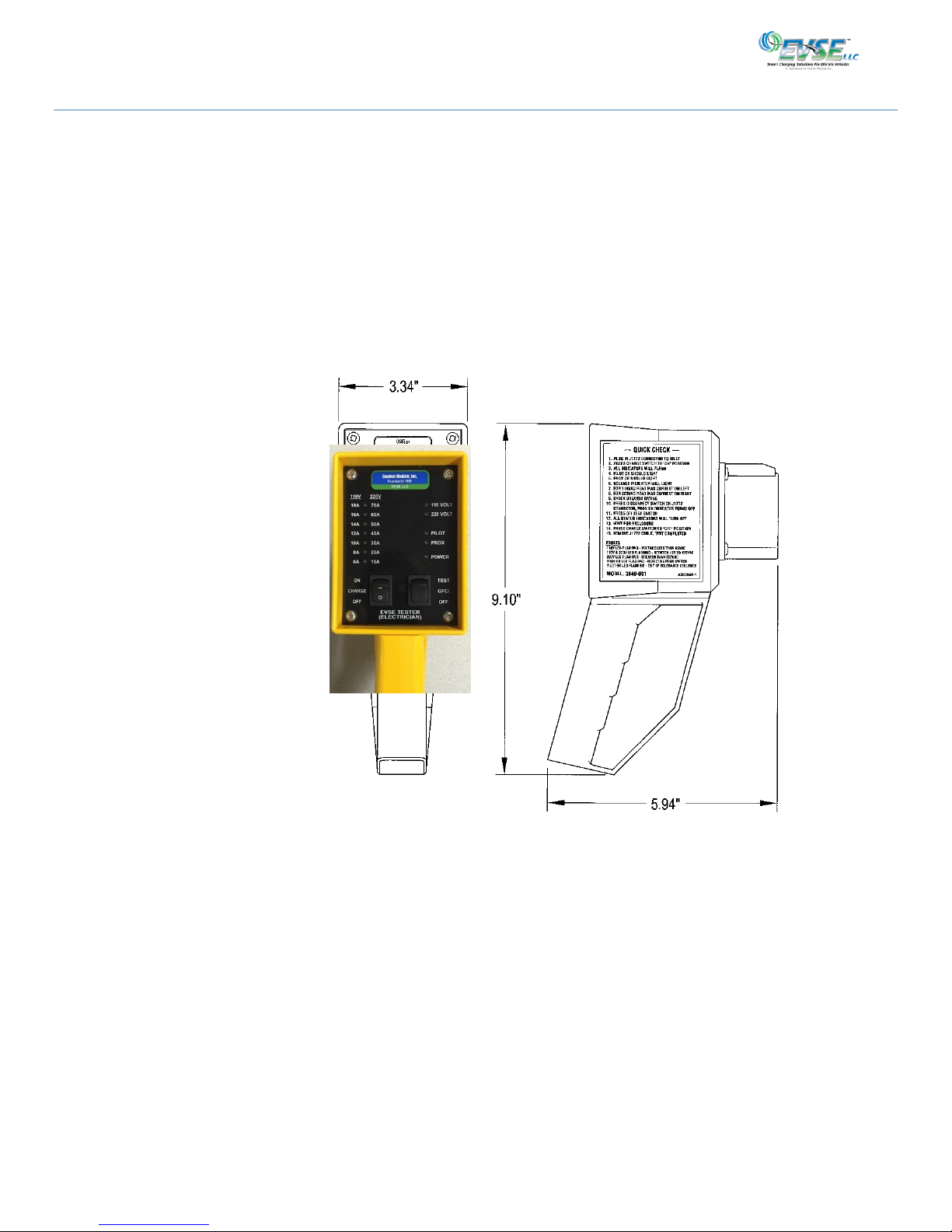
The unit is self-powered and requires no batteries. It is housed in a rugged, hand-held enclosure.
Figure 1

3840-001 User Manual February 22, 2018
Page 6
Specifications
Product Code__________________________________________________________________________________
Product Code
Model 3840-001
Emulates all electric vehicles that comply
with SAE J1772 standards
Electrical*_____________________________________________________________________________________
Voltage (Max)
Current (Max)
Up to 250 VAC
Up to 70 A
Connector
Ground Fault Test
J1772 Compatible
20ma, Line 1 to ground
Indicator LED’s
Voltage Status
Current Indicator
Measured:
0 to 250V, 0.1% accuracy
220V Range: 10A to 70A
110V Range: 6A to 18A
Pilot Signal
Frequency: 1kHz, 0.1% accuracy
Voltage: +15 to -15 VDC, 0.1% accuracy
Pilot Pulse Width
Proximity Signal
Power
10 to 90% duty cycle, 0.1% accuracy
Voltage: 0 to +5VDC, 0.1% accuracy
Safety Features_________________________________________________________________________________
Internal Fuse
Not user replaceable
Compliance____________________________________________________________________________________
Safety
IEC/UL/CSA C22.2 61010-1,NEC Article 625,
SAE J1772
EMC
FCC Part 15 Class A, Canadian ICES-003
Environmental__________________________________________________________________________________
Operating Temperature
0° to 122° F (-17° C to 50° C) ambient
Operating Humidity
Up to 95% non-condensing
NEMA Rating
Material
Drop Test
NEMA 3R
Bright Yellow, High Impact ABS, Plastic
3 foot drop to hard surface
General________________________________________________________________________________________
Weight
1.5 lbs (0.69 kg)
Dimensions
3.34 in (w) x 9.10 in (h) x 5.94 in (d)
*Observe all required Lockout/Tagout procedures while making any electrical connections or servicing the charging
station under test.

3840-001 User Manual February 22, 2018
Page 7
Product Description
The Model 3840 hand-held Electrician EVSE Tester was designed to provide a simple means of testing EVSE safety and operational
features. (Figure 2)
The control panel contains the following items:
(1) The range of currents that may be supplied to the electric vehicle from the EVSE under test, when powered from a 220VAC
source
(2) The range of currents that may be supplied to the electric vehicle from the EVSE under test when powered from a 110V AC
source
(3) Seven LED indicators to denote the maximum current that the EVSE under test is capable of supplying to the electric
vehicle. The value of this current is determined by the pulse width of the pilot signal received from the EVSE under test
(4) Charge on/off toggle switch necessary to activate the EVSE under test
(5) LED indicator to denote when the input voltage is between 95 and 125V AC
(6) LED indicator to denote when the input voltage is between 185 - 250V AC
(7) LED indicator to denote the presence and accuracy of the incoming pilot signal
(8) LED indicator to denote the presence and accuracy of the incoming proximity signal
(9) LED indicator to denote power is on/off
(10) Ground Fault Circuit Interrupter (GFCI) momentary switch, which applies a 20MA leakage path from line 1 to ground. This
will test the ground fault safety feature of the EVSE under test
The Enclosure:
(11) Rugged sealed high impact plastic enclosure
(12) Rugged handle
(13) “Quick Check” instructions
(14) SAE J1772 electric vehicle inlet
Figure 2
1
2
3
4
5
6
7
8
9
10
11
12
13
14
3840-001 User Manual February 22, 2018
Page 8
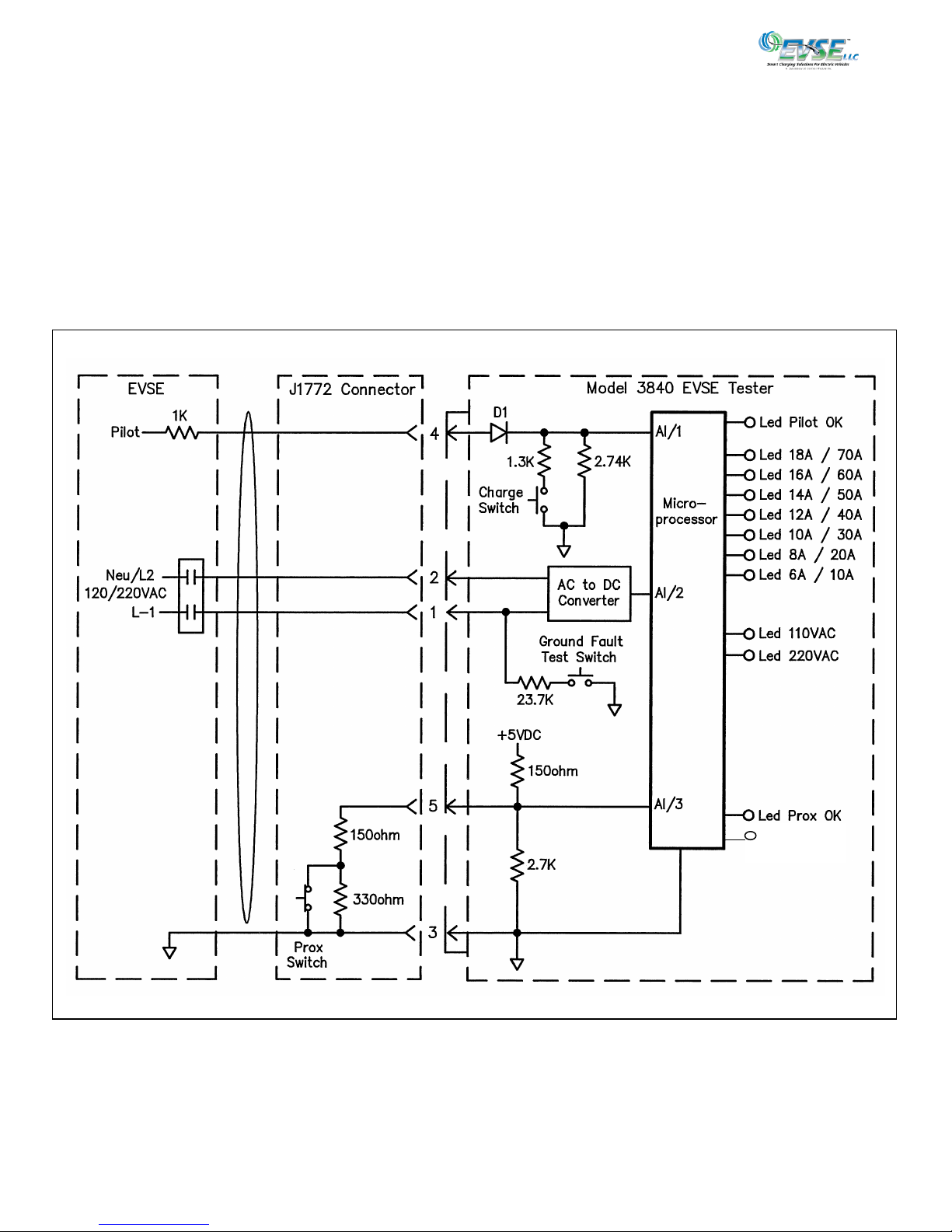
The Model 3840 uses an advanced microprocessor developed for the automotive industry. The microprocessor performs the
following functions (Figure 3):
Measures incoming line voltage from 0 to 250V AC
Measures incoming pilot signal amplitudes up to +/-15V DC with 0.1% accuracy
Measures pilot signal frequency (IKC) with 0.1% accuracy
Measures pilot signal pulse width, 0 to 95% duly cycle with 0.1% accuracy
Measures the proximity switch resistor with 0.1% accuracy
Controls 110V AC and 220V AC indicator LEDs
Controls pilot and proximity switch indicator LEDs
Controls seven current range indicator LEDs
Block Diagram
Led Power
Figure 3
3840-001 User Manual February 22, 2018
Page 9
Operation
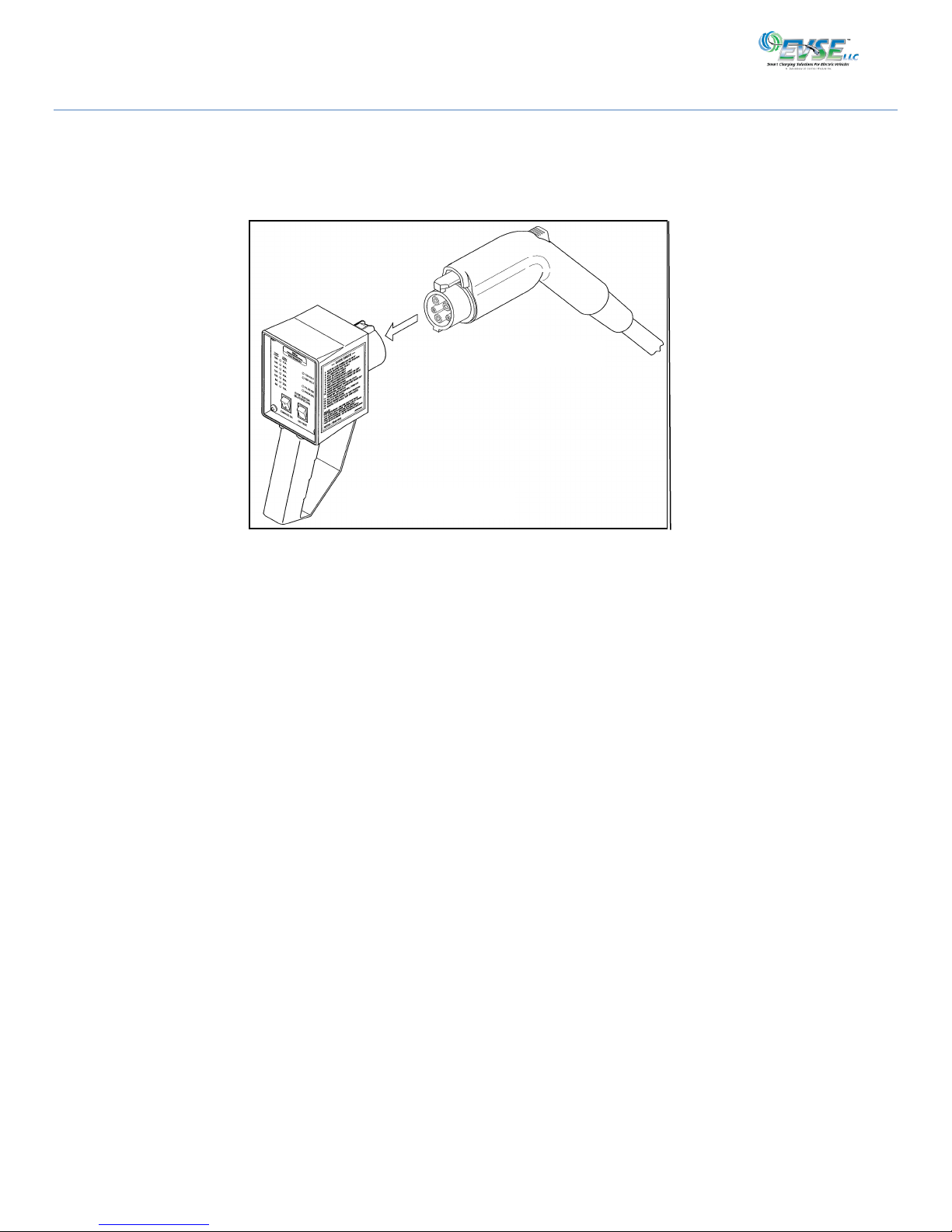
To test an EVSE, insert the J1772 connector of the EVSE under test into the J1772 inlet on the Model 3840 Tester (Figure 4).
Note: Your tester might have a cover over the SAE J1772 electric vehicle inlet. Press the latch on the right-hand side to
open the cover.
When the J1772 is inserted into the inlet, the Power LED lights, and the pilot voltage on Pin 4 (Figure 8) is reduced from +12VDC to
+9VDC with respect to Ground on Pin 3. This reduction in voltage signals the EVSE that the tester is connected. The EVSE in return
will convert the +9VDC signal to a +9VDC / -12VDC, square wave signal. The pulse width of this square wave will vary, from 10% to
95%, depending on the amount of current that the EVSE can supply to the Electric Vehicle.
In addition, a 150 ohm resistor to ground is connected to the Proximity input, Pin 5. This signals the tester that the J1772 connector
is attached and locked. The Model 3840 is now ready to test the EVSE.
When the Charge switch is toggled to the ON position (-), the Power LED will light up, the pilot signal will decrease to +6VDC peak.
This action will signal the EVSE to apply either 120VAC or 220VAC to Pins 1 and 2 on the Model 3840 Tester.
When AC power is applied to Pins 1 and 2, the microprocessor is activated and as a self-test, will sequentially light all of the status
LEDs.
The microprocessor will then measure the voltage on Pins 1 and 2, and depending on the amplitude, will light either the 110VAC or
220VAC status LED. When the AC voltage is between 185VAC and 250VAC, the 220V status LED is turned on steady. When the AC
voltage is between 95VAC and 125VAC, the 110V status LED is turned on steady. When the voltages are outside these ranges, the
voltage LEDs will flash (see Fault Conditions). The microprocessor will also measure the amplitude and pulse width of the pilot
signal. If the amplitude is within acceptable range, the maximum AC current available is determined by the microprocessor and
displayed by the current status LED indicators.
Based on the maximum current displayed, the rating of the service breaker should be 1.25 X the maximum current, i.e. 30A
displayed should be protected with a non-GFCI, 40A breaker. The maximum current displayed by the tester should never exceed the
rating displayed on the EVSE name plate. (The breaker rating should comply with all local and state electrical codes.) (Figure 5)
When the pilot signal is within the required J1772 specification, the pilot OK status LED is turned on steady. Should the pilot signal
not comply with the J1772 specification, the pilot LED will flash, indicating a problem (see Fault Conditions).
When the voltage, pilot and proximity status LEDs are on steady, the last two tests can be completed.
Figure 4
J1772 Connector
Model 3840 Tester

3840-001 User Manual February 22, 2018
Page 10
Press the release latch on the J1772 connector. (Do not remove the connector from inlet on Model 3840.) The proximity OK status
and Power LEDs should turn off when the release is pressed. (If not, see Fault Conditions). Push the J1772 connector back onto the
tester so that they lock back together.
Next, press the GFCI test momentary toggle switch to create a 20ma leakage current to ground. This should cause the EVSE under
test to drop AC power and indicate a ground fault condition. (If not, see Fault Conditions). All status LEDs on the Model 3840 will
turn off.
Most EVSE manufacturers will provide an automatic reclosure after a ground fault interception. Wait the specified time, and the
EVSE should once again supply voltage to the Model 3840 tester. (If not, see Fault Conditions).
The EVSE test is now completed.
EVSE Protection Breaker
The minimum breaker size shown in the chart is for reference only. If the size is not commercially available, use the next larger size.
All breakers and wire size must comply with local and state codes.
110VAC Min
Current Breaker
Displayed Size
18A 25A
16A 20A
14A 20A
12A 15A
10A 15A
8A 15A
6A 15A
220VAC Min
Current Breaker
Displayed Size
70A 100A
60A 80A
50A 65A
40A 50A
30A 40A
20A 25A
10A 15A
Figure 5
3840-001 User Manual February 22, 2018
Page 11
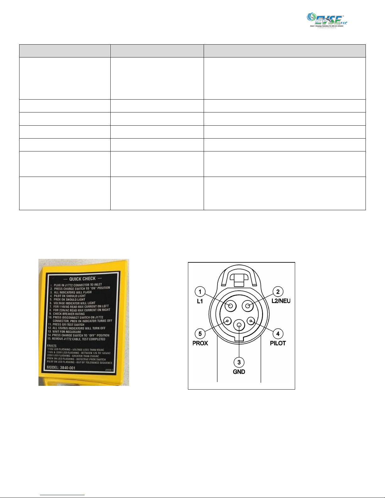
Fault Conditions
Action
Response
Problem
Press Charge Switch “On”
No Power LED
Check EVSE breaker
Check EVSE power
Check EVSE ground
Check Pin 4 to ground Pin 3. Should be between +11
to +13VDC
110V status LED flashes
Line voltage less than 95VAC
220V and 110V LED flash
Line voltage between 125 to 185VAC
220V status LED flashes
Line voltage above 250VAC
Pilot status LED OFF
Pilot frequency outside specification
Pilot status LED flashes
(Note 1)
Pilot voltage outside specification
Check Pin 4 to ground Pin 3. Should be between +11
to +13VDC
Press proximity locking latch
on J1772 Connector
Proximity status LED flashes
Locking latch not fully engaged
Measure resistance between Pin 5 and ground Pin 3.
Should be 150 ohms and change to 480 ohms when
lock latch is pressed
Note: Some manufacturers supply EVSE without the -12 VDC bias, which will be out of spec, but will still work with some electric
vehicles.
Quick Check
Figure 7 Figure 8
Connector Pin Out’s

3840-001 User Manual February 22, 2018
Page 12
User Maintenance
Perform the following preventative maintenance at least monthly:
The J1772 inlet should be checked for foreign matter, cleaned and dried with a mild detergent (safe for plastics),
and then allowed to dry.
Report mechanical damage.

3840-001 User Manual February 22, 2018
Page 13
Moving, Transporting and Storage
Retain the original shipping materials. Should the Model 3840-001 Electrician EVSE Tester need to be
returned to the factory or be otherwise shipped, use the original packing materials.
Store the unit in a dry, low humidity area.

3840-001 User Manual February 22, 2018
Page 14
Customer Support
Should questions about installation, operation, optional features, maintenance or service arise, please call Technical
Support at 1-888-753-8222 between the hours of 8:30 am to 5:00 pm EST, Monday to Friday.
Letter
Service Department
Attn: Jack Batalha, Director Product Support
Control Module Inc.
89 Phoenix Avenue
Enfield, CT 06082
Fax
1-860-741-6064
E-mail
jbatalha@controlmod.com

3840-001 User Manual February 22, 2018
Page 15
Warranty
For Standard Terms and Conditions, and Warranty information:
http://controlmod.com/technical-support/order-terms/

3840-001 User Manual February 22, 2018
Page 16
EVSE LLC
A Division of Control Module, Inc.
89 Phoenix Ave., Enfield, CT 06082
Local Phone: 860.745.2433
Toll Free Phone: 800.722.6654
evse.controlmod.com
EVSE LLC
A Division of Control Module, Inc.
89 Phoenix Ave., Enfield, CT 06082
Local Phone: 860.745.2433
Toll Free Phone: 800.722.6654
EVSE LLC
A Division of Control Module, Inc.
89 Phoenix Ave., Enfield, CT 06082
Local Phone: 860.745.2433
Toll Free Phone: 800.722.6654
evse.controlmod.com
Table of contents


 user manual")


