Ruby Tech VS-820S User manual

R
R
RU
U
UB
B
BY
Y
YT
T
TE
E
EC
C
CH
H
H
V
V
VS
S
S-
-
-8
8
82
2
20
0
0S
S
S
8x SFP Slots with 2 Giga unmanaged Ethernet Switch
USER’s MANUAL

VS-820S 8 SFP Slots with 2 Giga
unmanaged Ethernet Switch
1
Copyright
Copyright © 2020 by RubyTech Deutschland GmbH All rights reserved.
Legal Disclaimer
The information given in this document shall in no event be regarded as a guarantee of conditions or characteristics. With respect
to any examples or hints given herein, any typical values stated herein and/or any information regarding the application of the
device, RubyTech Deutschland GmbH hereby disclaims any and all warranties and liabilities of any kind, including without
limitation warranties of non-infringement of intellectual property rights of any third party.
Statement of Conditions
In the interest of improving internal design, operational function, and/or reliability, RUBYTECH DEUTSCHLAND GMBH reserves the
right to make changes to the products described in this document without notice. RUBYTECH DEUTSCHLAND GMBH does not
assume any liability that may occur due to the use or application of the product(s) or circuit layout(s) described herein.
Maximum signal rate derived from IEEE Standard specifications. Actual data throughput will vary. Network conditions and
environmental factors, including volume of network traffic, building materials and construction, and network overhead, lower actual
data throughput rate. RubyTech Deutschland GmbH does not warrant that the hardware will work properly in all environments and
applications, and makes no warranty and representation, either implied or expressed, with respect to the quality, performance,
merchantability, or fitness for a particular purpose. Make sure you follow in line with the environmental conditions to use this product.

VS-820S 8 SFP Slots with 2 Giga
unmanaged Ethernet Switch
2
Foreword
VS-820S is an unmanaged SFP switch, each SFP port especial designed support high power source for feeding high power
consumption SFP module as VDSL2-SFP / G.fast-SFP module, if install them it can be became a unmanaged IP DSLAM, or
mixing install VDSL2-SFP / G.fast-SFP module plus Fiber optical module to extend your networking services and applications
to farther places. VS-820S also supports isolation function on SFP port for security, which can be easily configured by
slide switch on front panel. There are lots of Multi-ple ports SFP switches in the market always power source is not enough
to driver VDSL2-SFP / G.fast module or encounter overheat issue. Therefore, RubyTech Deutschland GmbH company put lots of
effort for power source and
good heat dissipation as VS-820S's SFP slots are separated to each other, and build in two internal fans to prevent SFP module
overheat issue. With high performance and easy installation, VS-820S can be utilized in ISP network solution for FTTdp(Fiber to
the distribution point), FTTC (Fiber to the Curb) and FTTB (Fiber to the Building), also for SOHO application.
Attention:
Be sure to read this manual carefully before using this product. Especially Legal Disclaimer, Statement
of Conditions and Safety Warnings.
Caution:
The VS-820S is for indoor applications only. This product does not have waterproof protection. Do not use in harsh environments
(Over temperature range: 0°C ~ 50°C (32°F ~ 122°F)).

VS-820S 8 SFP Slots with 2 Giga
unmanaged Ethernet Switch
3
Safety Warnings
For your safety, be sure to read and follow all warning notices and instructions before using the device.
DO NOT open the device or unit. Opening or removing covers can expose you to dangerous high voltage points or other
risks. ONLY qualified service personnel can service the device. Please contact your vendor for further information.
Use ONLY the dedicated power supply for your device. Connect the power cord to the right supply voltage (110V AC used
for North America and 230VAC used for Europe).
DO NOT use the device if the power supply is damaged as it might cause electrocution. If the power supply is damaged,
remove it from the power outlet. DO NOT attempt to repair the power supply. Contact your local vendor to order a new
power supply.
Place connecting cables carefully so that no one will step on them or stumble over them. DO NOT allow anything to rest on
the power cord and do not locate the product where anyone can work on the power cord.
DO NOT install nor use your device during a thunderstorm. There may be a remote risk of electric shock from lightning.
DO NOT expose your device to dampness, dust or corrosive liquids.
DO NOT use this product near water, for example, in a wet basement or near a swimming pool.
Connect ONLY suitable accessories to the device. Make sure to connect the cables to the correct ports.
DO NOT obstruct the device ventilation slots, as insufficient airflow may harm your device.

VS-820S 8 SFP Slots with 2 Giga
unmanaged Ethernet Switch
4
DO NOT place items on the device.
DO NOT use the device for outdoor applications, and make sure all the connections are indoors. There may be a remote
risk of electric shock from lightning.
Be careful when unplugging the power, because the transformer may be very hot.
Keep the device and all its parts and accessories out of children’s reach.
Clean the device using a soft and dry cloth rather than liquid or atomizers. Power off the equipment before cleansing it.
This product is recyclable. Dispose of it properly.

VS-820S 8 SFP Slots with 2 Giga
unmanaged Ethernet Switch
5
Table of Contents
Copyright ............................................................................................................................................................ 2
Foreword ............................................................................................................................................................ 3
Safety Warnings ................................................................................................................................................. 4
Chapter 1. Unpacking Information ................................................................................................................... 7
1.1 Check List ................................................................................................................................................................................. 7
Chapter 2. Installing the Device ...................................................................................................................... 8
2.1 Hardware Installation .................................................................................................................................................................8
2.2 Pre-installation Requirements ....................................................................................................................................................8
2.3 Connecting the Ethernet of RJ-45 Ports ................................................................................................................................... 9
2.4 Connecting the SFP Slot ........................................................................................................................................................... 9
2.5 Application Diagram ................................................................................................................................................................ 10
Chapter 3. Hardware Description ..................................................................................................................... 11
3.1 Front panel………………………………………………………………………………………………………………………………….11
3.2 LED Indicators ........................................................................................................................................................................ 13
Appendix A: Cable Requirements……………………………………………………………………………………...14
Appendix B: Product Specification ................................................................................................................. 16
Appendix C: Mounting the Switch on a Rack………………………………………………………………………. 18
Appendix D: Troubleshooting .......................................................................................................................... 19
Appendix E: Compliance and Safety Information .......................................................................................... 22
Warranty ........................................................................................................................................................... 25
VS-820S 8 SFP Slots with 2 Giga
unmanaged Ethernet Switch
6
Unpacking In formation
1.1 Check List
Carefully unpack the package and check its contents against the check list.
Package Contents:
1 x VS-820S 1 x QR code for user’s
Accessory:
1 x AC Power Cord, 2 X Rack mount bracket (optional) ,
8 x SFP cover
Notes:
1. Please inform your dealer immediately for any missing or damaged parts. If possible, retain the carton including the
original packing materials. Use them to repack the unit in case there is a need to return for repair.
2. If the product has any issue, please contact your local vendor.
3. Please make sure power source is compliant with required specification.
4. VS-820S is a commercial-grade product. Do not use in industrial-grade applications.
5. Please look for the QR code on the bottom of the product, the user can launch the QR code scanning program to
scan and download the user’s manual electronic format file. Above QR code icon is for reference.

VS-820S 8 SFP Slots with 2 Giga
unmanaged Ethernet Switch
7
Installing the Device
2.1 Hardware Installation
This chapter describes how to install the device and establish the network connections. The VS-820S may be
installed on any level surface (e.g. a table or shelf, 19 inch rack or wall mounting). However, please take note of the
following minimum site requirements before one begin.
4 rubber feet on the bottom has been pre-installed.
2.2 Pre-installation Requirements
Before you start the actual hardware installation, make sure you can provide the right operating environment, including
power requirements, sufficient physical space, and proximity to other network devices that are to be connected.
Verify the following installation requirements:
Power requirements: AC 100-240 volts / 50-60 Hz
The device should be located in a cool dry place, with at least 10cm/4in of space at the front and back for
ventilation.
Place VS-820S away from direct sunlight, heat sources, or areas with a high amount of electromagnetic
interference.
Check if the network cables and connectors needed for installation are available.
Do not install phone lines strapped together with AC power lines, or telephone office line with voice signal.
Avoid installing this device with radio amplifying station nearby or transformer station nearby.

VS-820S 8 SFP Slots with 2 Giga
unmanaged Ethernet Switch
8
2.3 Connecting the Ethernet of RJ-45 Ports
VS-820S has two Ethernet ports which support connection to Ethernet operation. The devices attached to these ports must support
auto-negotiation or 10Base-T, 100Base-T or 1000Base-T, and note they don’t support half duplex. Use any of the Ethernet ports to
connect to devices such as Monitor system, Server, Backbone switch, or IP gateway.
2.4 Connecting the SFP Slot
There are multiple types of SFP module in market, please make sure the SFP module support 1000X/SerDes mode; otherwise, the
connection can’t set up any more.

VS-820S 8 SFP Slots with 2 Giga
unmanaged Ethernet Switch
9
2.5 Application Diagram
VS-820S is an ideal solution for FTTC/FTTB, MDU usage and SOHO application. VS-820S can either be used as an upstream
internet provider or a downstream internet receiver in your Network system, which makes VS-820S meet user’s requirement, and
offer you a variety of combination with other networking devices. With 8 SFP slots and suitable SFP transceiver, VS-820S is able to
be considered as an IPDSLAM, and would perfectly fit in Fiber / XDSL networking system. VS-820S also enable user to segment
their SFP network, and set up multiple isolated network at your premises, such as your home, office, school, etc. (Figure 2.5.1)
Figure 2.5.1 Application Diagram

VS-820S 8 SFP Slots with 2 Giga
unmanaged Ethernet Switch
10
Hardware Description
This section describes the important parts of VS-820S. It features the front panel and rear panel.
3.1 Front Panel:
The front panel shown as interface with 8 x SFP Slots, 2 x RJ-45 Connector, Slide switch for Isolation function
and
LED indicators.
3.1.1 Front panel indicator:
There are 16 LED indicators on front panel, the following Table shows the description.
Figure 3.1 Front Panel
Tip: With only a glance of the front panel’s LED indicators, the converter status will be fully aware.

VS-820S 8 SFP Slots with 2 Giga
unmanaged Ethernet Switch
11
Table 3-1 Description of the front interface
Reminder:
Please use SFP transceiver which is compatible to 1000Base-X SFP slot, otherwise, the connection cannot set up.
3.1.2 Slide switch
For setting SFP port isolation mode. To activate isolation function, slide the switch to ON.
3.1.3 Rear Panel
The rear panel provides AC Power Jack and two built-in internal fans.
Figure 3.1.3 Rear Panel

VS-820S 8 SFP Slots with 2 Giga
unmanaged Ethernet Switch
12
3.2 LED Indicators
The VS-820S has 16 LED indicators. The following Table shows the description. (Table 3-2)
Table 3-2 LED Indicators Description and Operation
Remark: 1. Except for Fiber SFP transceiver, SFP LED indicator will light up right away when the SFP transceiver is
inserted into SFP slot.

VS-820S 8 SFP Slots with 2 Giga
unmanaged Ethernet Switch
13
Appendix A: Cable Requirements
A.1 Ethernet Cable
A CAT 5~7 UTP (unshielded twisted pair) cable is typically used to connect the Ethernet device to the Modem. A: 10/100TX
cable often consists of four pairs of wires, two of which are used for transmission. The connector at the end of the
10/100TX cable is referred to as a RJ-45 connector and it consists of eight pins. The Ethernet standard uses pins 1, 2, 3
and 6 for data transmission purposes. (Table A-1 10/100TX)
B: 1000TX cable often consists of four pairs of wires, all of which are used for transmission. The connector at the end of the
1000TX cable is referred to as a RJ-45 connector and it consists of eight pins. The Ethernet standard uses pins 1, 2, 3, 4, 5
and 6 for data transmission purposes. (Table A-1 1000TX)
Table A-1 RJ-45 Ethernet Connector Pin Assignments

VS-820S 8 SFP Slots with 2 Giga
unmanaged Ethernet Switch
14
Figure A-2 Pin Assignments and Wiring for an RJ-45 Straight-Through Cable

VS-820S 8 SFP Slots with 2 Giga
unmanaged Ethernet Switch
15
Figure A-3 Pin Assignments and Wiring for an RJ-45 Crossover Cable

VS-820S 8 SFP Slots with 2 Giga
unmanaged Ethernet Switch
16
Product Specification
Key Features and Benefits:
Supports 2 x 10/100/1000BASE-T & auto–MDIX for RJ-45 port
Supports 8 x 1.25G SFP Slots
Cost effective bridge function for FTTdp/FTTC application
Compatible to VDSL2 SFP module
Support per SFP slot power source up to 3W
Special design for VDSL2/G.fast-SFP module heat dissipation
Supports isolation mode by Slide switch
Compact in size, easy installation
Plug & Play
Flexible application & installation
Support MTU 1632 bytes
Supports 19” Rack mount bracket

VS-820S 8 SFP Slots with 2 Giga
unmanaged Ethernet Switch
17
Specification:

VS-820S 8 SFP Slots with 2 Giga
unmanaged Ethernet Switch
18
Appendix D: Troubleshooting
Diagnosing Switch’s Indicators
The Bridge can be easily monitored through its comprehensive panel indicators. These indicators assist in identifying problems the
Media Converter may encounter. This section describes common problems you may encounter and possible solutions:
1. Symptom: POWER indicator does not light up (green) after power on. Cause: Defective power source or power supply.
Solution: Check the power source by using another power cord that is functioning properly. Check the power cord with another
device. If these measures fail to resolve the problem, have the unit sent back to a qualified distributor.
2. Symptom: Link indicator does not light up (green) after making a connection.
Cause: Network interface (ex. a network adapter card on the attached device), network cable, or SFP transceiver defective.
Solution:
Verify if both of the VS-820S (all devices) and attached device are powered on.
Be sure the Ethernet cable and fiber optics are plugged into both the switch and corresponding
device.
Verify that the proper cable type is used and its length does not exceed specified limits.
Check the cable connections for possible defects.
Replace the defective cable if necessary.
Please make sure SFP transceiver support 1.25G Serdes mode
3. Symptom: RJ-45 port link LED light up without transmission.Cause: RJ-45 port link on half duplex mode or LED jitter happen

VS-820S 8 SFP Slots with 2 Giga
unmanaged Ethernet Switch
19
Solution: Please make sure opposite side device setting on full duplex mode, since VS-820S doesn’t support helf duplex mode. If
LED jitter it mean both internal chipset without compatible.
Power and Cooling Problems
If the POWER indicator does not turn on when the power cord is plugged in, you may have a problem with the power outlet, power
cord, or internal power supply. However, if the unit power is off after running for a while, check for loose power connections, power
losses or surges at the power outlet. If you still cannot isolate the problem, then the internal power supply may be defective. In this
case, please contact your local dealer.
Installation
Verify that all system components have been properly installed. If one or more components appear to be malfunctioning (e.g. the
power cord or network cabling), test them in an alternate environment where you are sure that all the other components are
functioning properly.
Transmission Mode
The default of transmission mode for RJ-45 ports is 10/100/1000 Mbps Ethernet, SFP port is 1.25Gbps (1000Base-X). Therefore, if
the Link signal is disrupted (e.g. by unplugging the network cable and plugging it back in again, or by resetting the power), the port
will try to re-establish connection with the attached device via auto-negotiation.
Physical Configuration
If problems occur after altering the network configuration, restore the original connections, and try to track the problem down by
implementing the new changes, one step at a time. Ensure that cable distances and other physical aspects of the installation do not
exceed recommendations.
System Integrity
As a last resort verify the switch integrity with a power-on reset. Turn the power to the switch off and then on several
times. If the problem still persists and you have completed all the preceding diagnoses, then contact your dealer.
Table of contents
Other Ruby Tech Network Router manuals

Ruby Tech
Ruby Tech ES-2310C User manual

Ruby Tech
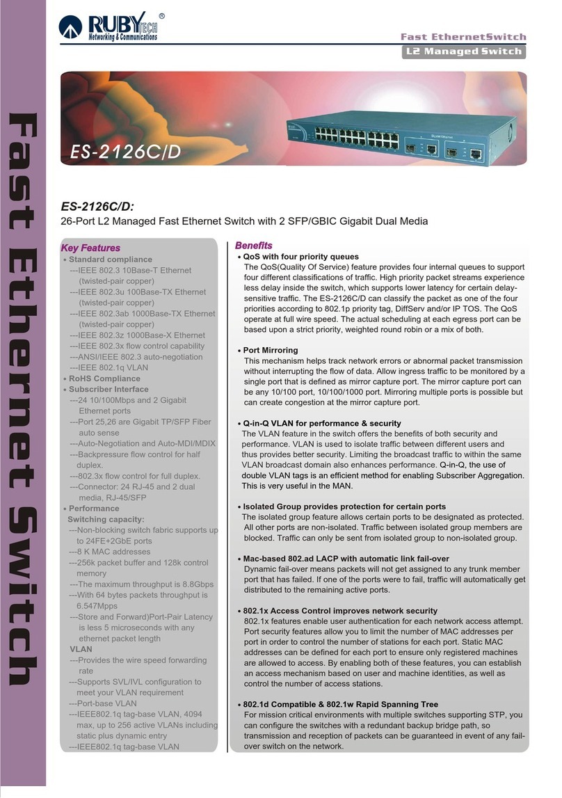
Ruby Tech ES-2126C/D User manual

Ruby Tech
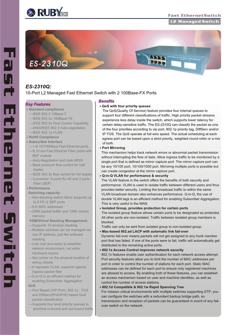
Ruby Tech ES-2310Q User manual

Ruby Tech
Ruby Tech VC-400RT+ User manual

Ruby Tech
Ruby Tech ES-2410C User manual

Ruby Tech
Ruby Tech PSES-5308 User manual

Ruby Tech
Ruby Tech CR-2010 User manual

Ruby Tech
Ruby Tech IES-2310C User manual

Ruby Tech
Ruby Tech GS-1108C User manual

Ruby Tech
Ruby Tech VC-450RT User manual